


RC18GT


 05-24-2013, 08:48 AM
#3
Senior Member
Thread Starter
Join Date: May 2013
Posts: 223
Likes: 0
Received 0 Likes
on
0 Posts
OK, you asked for it 
(Warning-pic heavy)
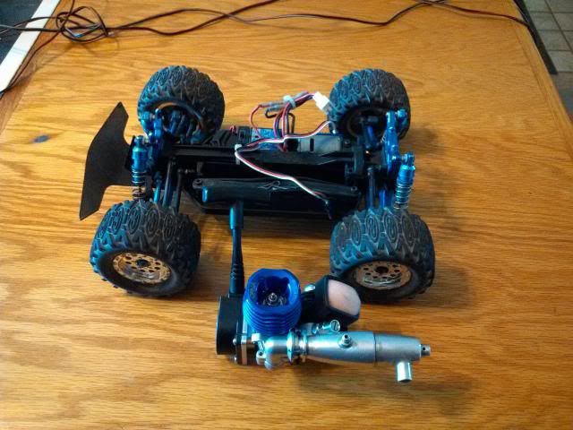
So, we started out with an eBay score on a nice used RC18T that had the billet kit and MT tires, and came with a box full of goodies for $85 shipped-so much in fact, that when I saw the shipping charges the guy paid, I decided he should pocket more than $55 after fees, so sent him a check for a little more. There was probably $700+ in original purchase price sitting there!
The Picco P-zero was another screamin’ eBay deal, at $42 shipped new in the box. I got all the engine accessories (flywheel, clutch shoes, bell, mount, exhaust, etc.) from gonitroonline.com for $47 shipped, though the final version wears a Chaos sportworks snorkel type air cleaner.
Anyway, first order of business was figuring out exactly how I was going to do this. I had never actually looked at an RC18 chassis until now, and there ain’t much real estate there. I knew I could do it, but it wouldn’t be easy to fit everything that needed to fit.
Now before anyone asks, no, I don’t have templates/plans of any kind. I’m an old school builder, and I rarely make measurements and almost never draft. I just go for it, and when things don’t quite fit, I rearrange them or alter parts until they do. I’ll use a ruler or mic occasionally to get holes of the right size in the right place, but for the most part, I just eyball it.
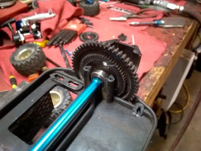
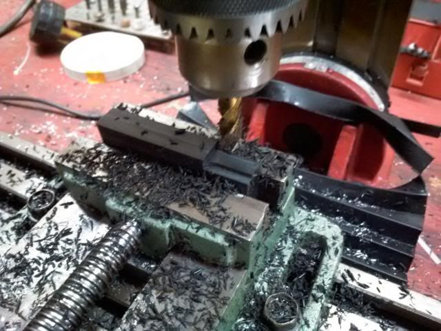
First order of business was making sure that it was possible to use the existing drivetrain with a nitro motor, meaning could I figure out a 32P spur gear set-up that would fit more-or-less where the existing spur did, and would I still have room to mount the engine? The answer is, with some creativity, some spare parts and a lathe, yes. I took a 52T Nitro TC3 spur gear and machined it down to fit in the narrow channel where the original gear did, but the much larger diameter meant cutting a slot in the bottom of the chassis and cutting the top brace, which would leave the chassis very weak. Further down, we’ll get into how that was dealt with.
The modified TC3 gear was then screwed to the slimmed down remainder of the original RC18 spur with three M3 machine screws, and nestled into the newly enlarged slot:
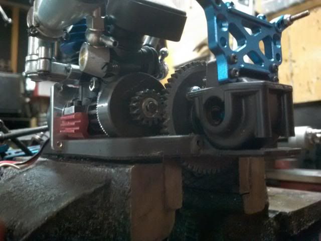
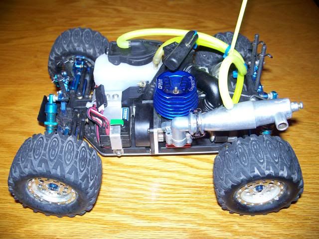
And success! There was just enough room for the engine to mount in the existing chassis pan and properly mesh clutch bell and spur:
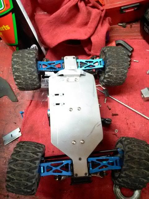
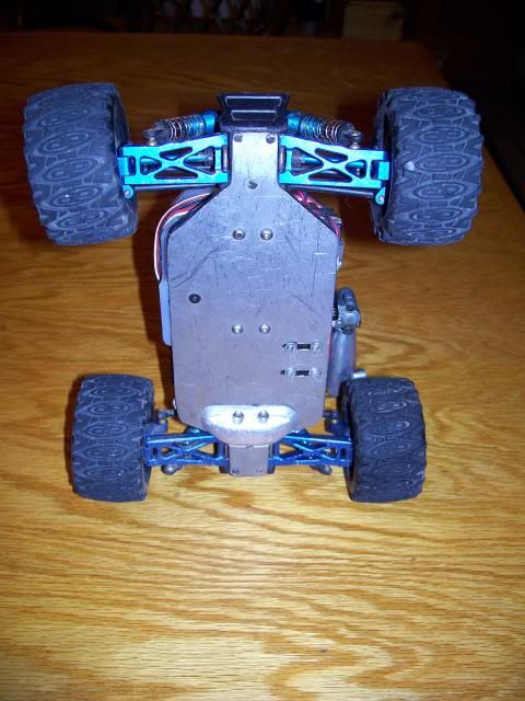
To deal with the weak plastic chassis that was further compromised by material removal, I cut a piece of 16ga steel to exactly fit the RC18 tub nose to tail:
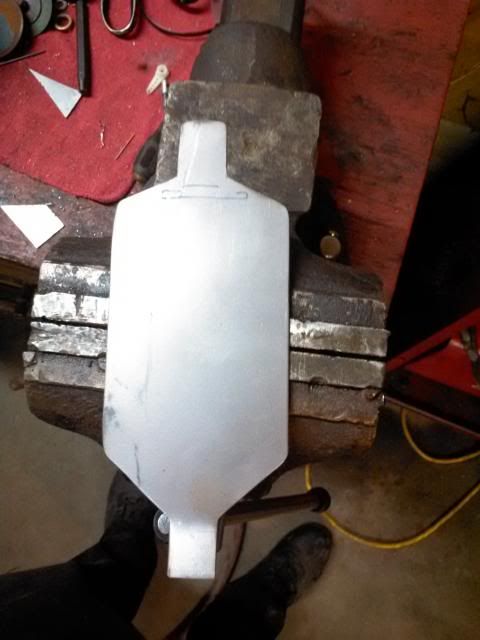
And secured it with six M3 screws, in addition to running differential screws and engine mount screws all the way through:
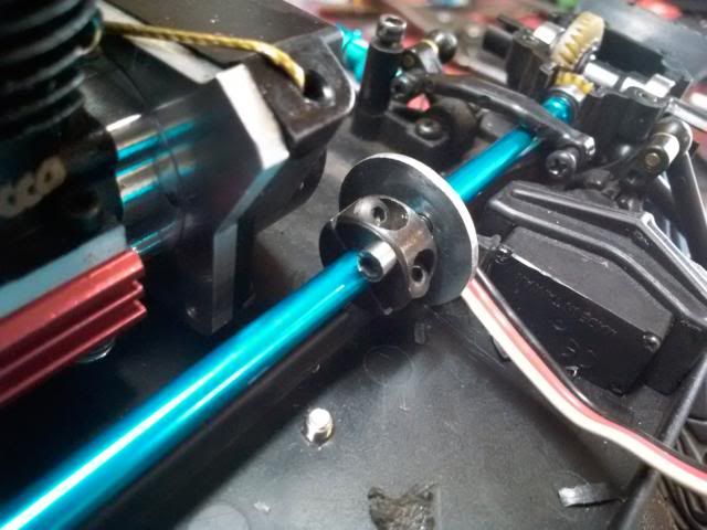
The next challenge was figuring out a braking system. Once again, the lack of real estate on the tiny chassis presented a challenge here. I already had an idea of how I wanted to go about this, so I went to the hardware store to see what I might find that would make my life a little easier. I decided the best way was a center shaft disc brake, and that the simplest way to accomplish rotor mounting would be the use of a split collar. I bought a 1/8” collar, which I bored out to fit the .178” center shaft and drilled/tapped to accept two #3-48 machine screws:
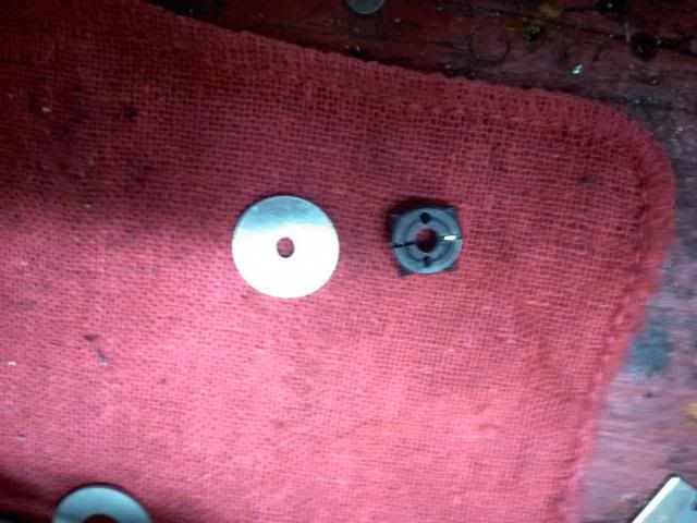
The rotor itself is a 1/8” steel fender washer with a ¾” OD, which I bored a bit larger than the shaft so it could float on the two 3-48 screws (which are depth-set with two more short screws from the back, since blind hole tapping a <1/4” thick collar is nigh impossible:
Of course, the rotor would require clearance that came in the form of cutting the upper chassis brace again:
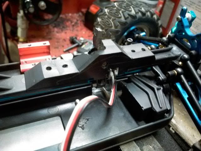
But this worked out well, as the new raised section of chassis brace could double as a brake caliper. I milled the piece from scratch out of black ABS stock:
And fitted it carefully to the remaining pieces of original chassis brace:
For brake pads, I initially used hand cut pieces of aluminum for backing plates and glued bits of fiber washer to them:
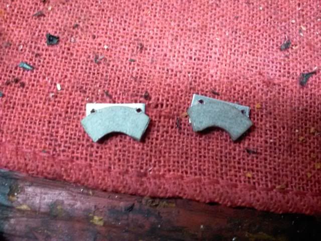
This worked for initial testing, but I could not keep the pieces bonded, so ended up ordering a set of NTC3 brake pads and cutting them to fit for the final version.
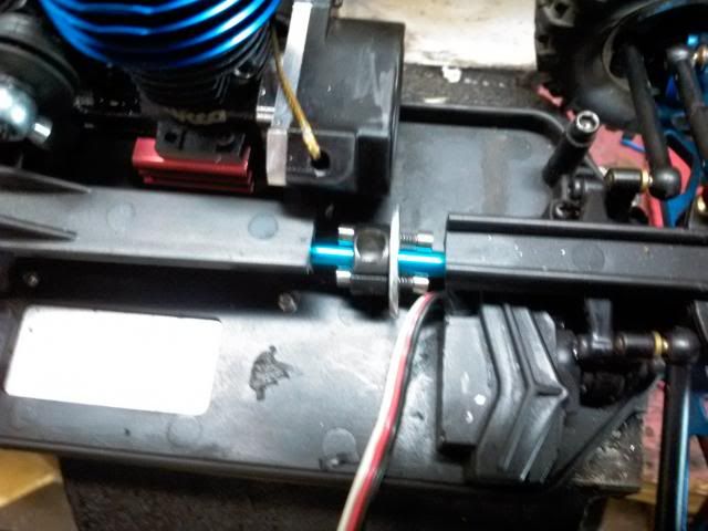
The actuating mechanism is quite simple, just a pivoting arm that pushes on the rear brake pad and moves the floating rotor forward into the fixed front pad:
Unfortunately, I got a bit lazy about taking pictures from here, so I’ll describe in the best detail possible the remainder.
Once I had the brake sorted out, it was most just fitting parts to the chassis. I did have to make a custom piece to join the rear diff/shock tower to the rest of the chassis brace, which was done with another chunk of black ABS.
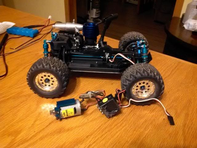
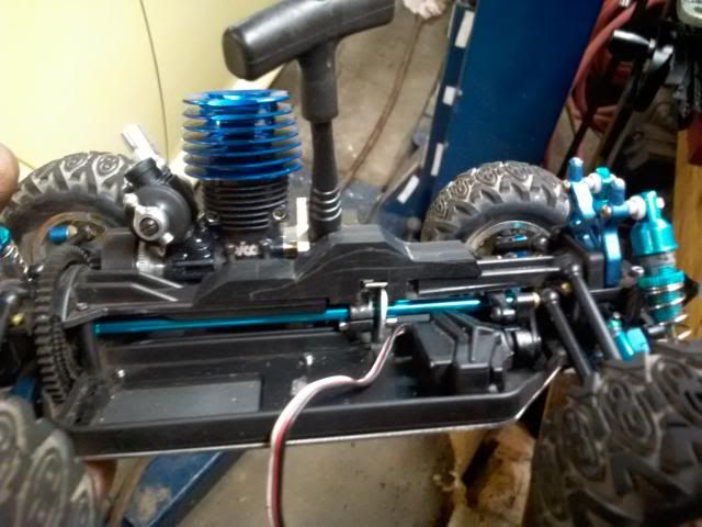
For brake/throttle, I opted to use a full size Futaba servo, one because I had it and two, because I didn’t feel that a micro servo would have enough torque to properly actuate the brake. This was the layout pre-fuel tank and before I decided to use a Losi micro NiMh battery as the servo pack and relocate the receiver to the driver side:
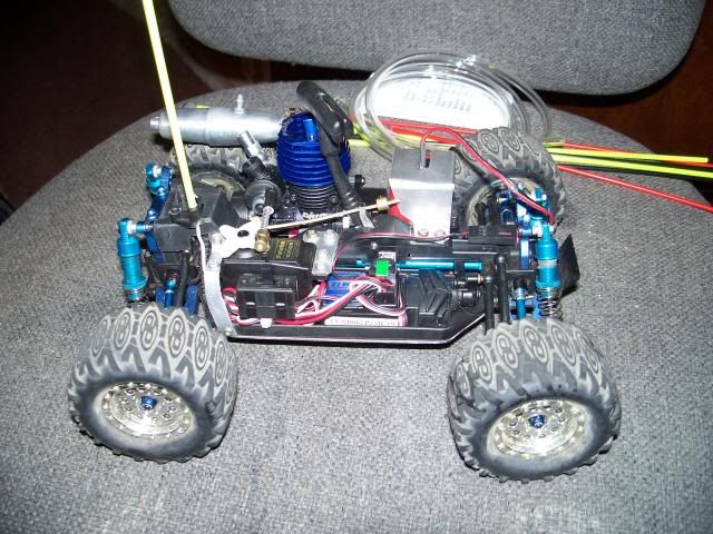
Everything was coming together pretty well, but the last major hurdle was a fuel tank. With little room left, I knew this was going to be tricky. I had ordered a Chaos 1/16 tank just to try, but there was no clean way to mount that, so I moved to what I thought would be the next most logical route; modify an existing fuel tank, of which I had several for RC10GT. So I cut, melted and glued until I had what seemed like a sealed tank:
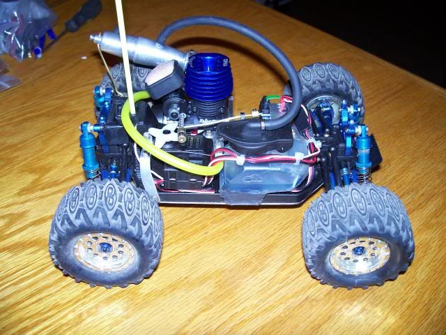
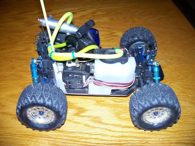
Of course, nitro is very hard on adhesives, and this tank would prove a failed effort after a half dozen attempts to seal it, and it wrecked the steering servo that lived under it. In the end, I milled a tank from scratch using solid opaque poly ethylene. It is perfectly fitted to the chassis, with the top epoxied to the rest of the tank and held together with two 0-80 screws in opposing corners. It’s working so far.
After several times taking things back apart to shim or clearance on account of binding, I finally had a truck that would roll freely and drive. First test drives proved mostly successful, except that the flimsy sheet aluminum lower gear cover was too weak and the spur gear was too open, constantly allowing small rocks to enter and jam up the works.
The final version (for now) uses a milled piece of 7075-T6 for the lower gear cover, and the clutch bell and spur are completely shrouded with aluminum.
The body posts are Losi micro T, attached to the existing shock posts with 0-80 screws

It runs pretty well, a bit sluggish off the line, but with a rather high 40+ MPH top speed. I’d like to gear it lower, but there simply isn’t room for a larger spur, nor can I find a .05 size clutch bell with fewer than 15 teeth. Since this will be the final drivetrain set-up, I now have aluminum gears en route for longer life, since changing a spur is a royal pain on this thing.
It’s certainly not as fast as a powerful brushless set up would have been, but it’s much more unique. The end result is a bit top heavy, and has gained a full pound over the electric version, but it’s still a lot of fun.
It’s difficult to calculate the exact cost, since I had many things on hand, but I’d say all total, I’m not into the project for more than ~$300. Yeah, I could have just bought an Xray NT18T for $200 and been done with it, but I’m a born tinkerer, and I’m also an Associated guy when it comes to RC. What I have now is a truly one-of-a-kind RC18!
Thanks for reading, hope you enjoyed!
(Warning-pic heavy)
So, we started out with an eBay score on a nice used RC18T that had the billet kit and MT tires, and came with a box full of goodies for $85 shipped-so much in fact, that when I saw the shipping charges the guy paid, I decided he should pocket more than $55 after fees, so sent him a check for a little more. There was probably $700+ in original purchase price sitting there!
The Picco P-zero was another screamin’ eBay deal, at $42 shipped new in the box. I got all the engine accessories (flywheel, clutch shoes, bell, mount, exhaust, etc.) from gonitroonline.com for $47 shipped, though the final version wears a Chaos sportworks snorkel type air cleaner.
Anyway, first order of business was figuring out exactly how I was going to do this. I had never actually looked at an RC18 chassis until now, and there ain’t much real estate there. I knew I could do it, but it wouldn’t be easy to fit everything that needed to fit.
Now before anyone asks, no, I don’t have templates/plans of any kind. I’m an old school builder, and I rarely make measurements and almost never draft. I just go for it, and when things don’t quite fit, I rearrange them or alter parts until they do. I’ll use a ruler or mic occasionally to get holes of the right size in the right place, but for the most part, I just eyball it.
First order of business was making sure that it was possible to use the existing drivetrain with a nitro motor, meaning could I figure out a 32P spur gear set-up that would fit more-or-less where the existing spur did, and would I still have room to mount the engine? The answer is, with some creativity, some spare parts and a lathe, yes. I took a 52T Nitro TC3 spur gear and machined it down to fit in the narrow channel where the original gear did, but the much larger diameter meant cutting a slot in the bottom of the chassis and cutting the top brace, which would leave the chassis very weak. Further down, we’ll get into how that was dealt with.
The modified TC3 gear was then screwed to the slimmed down remainder of the original RC18 spur with three M3 machine screws, and nestled into the newly enlarged slot:
And success! There was just enough room for the engine to mount in the existing chassis pan and properly mesh clutch bell and spur:
To deal with the weak plastic chassis that was further compromised by material removal, I cut a piece of 16ga steel to exactly fit the RC18 tub nose to tail:
And secured it with six M3 screws, in addition to running differential screws and engine mount screws all the way through:
The next challenge was figuring out a braking system. Once again, the lack of real estate on the tiny chassis presented a challenge here. I already had an idea of how I wanted to go about this, so I went to the hardware store to see what I might find that would make my life a little easier. I decided the best way was a center shaft disc brake, and that the simplest way to accomplish rotor mounting would be the use of a split collar. I bought a 1/8” collar, which I bored out to fit the .178” center shaft and drilled/tapped to accept two #3-48 machine screws:
The rotor itself is a 1/8” steel fender washer with a ¾” OD, which I bored a bit larger than the shaft so it could float on the two 3-48 screws (which are depth-set with two more short screws from the back, since blind hole tapping a <1/4” thick collar is nigh impossible:
Of course, the rotor would require clearance that came in the form of cutting the upper chassis brace again:
But this worked out well, as the new raised section of chassis brace could double as a brake caliper. I milled the piece from scratch out of black ABS stock:
And fitted it carefully to the remaining pieces of original chassis brace:
For brake pads, I initially used hand cut pieces of aluminum for backing plates and glued bits of fiber washer to them:
This worked for initial testing, but I could not keep the pieces bonded, so ended up ordering a set of NTC3 brake pads and cutting them to fit for the final version.
The actuating mechanism is quite simple, just a pivoting arm that pushes on the rear brake pad and moves the floating rotor forward into the fixed front pad:
Unfortunately, I got a bit lazy about taking pictures from here, so I’ll describe in the best detail possible the remainder.
Once I had the brake sorted out, it was most just fitting parts to the chassis. I did have to make a custom piece to join the rear diff/shock tower to the rest of the chassis brace, which was done with another chunk of black ABS.
For brake/throttle, I opted to use a full size Futaba servo, one because I had it and two, because I didn’t feel that a micro servo would have enough torque to properly actuate the brake. This was the layout pre-fuel tank and before I decided to use a Losi micro NiMh battery as the servo pack and relocate the receiver to the driver side:
Everything was coming together pretty well, but the last major hurdle was a fuel tank. With little room left, I knew this was going to be tricky. I had ordered a Chaos 1/16 tank just to try, but there was no clean way to mount that, so I moved to what I thought would be the next most logical route; modify an existing fuel tank, of which I had several for RC10GT. So I cut, melted and glued until I had what seemed like a sealed tank:
Of course, nitro is very hard on adhesives, and this tank would prove a failed effort after a half dozen attempts to seal it, and it wrecked the steering servo that lived under it. In the end, I milled a tank from scratch using solid opaque poly ethylene. It is perfectly fitted to the chassis, with the top epoxied to the rest of the tank and held together with two 0-80 screws in opposing corners. It’s working so far.
After several times taking things back apart to shim or clearance on account of binding, I finally had a truck that would roll freely and drive. First test drives proved mostly successful, except that the flimsy sheet aluminum lower gear cover was too weak and the spur gear was too open, constantly allowing small rocks to enter and jam up the works.
The final version (for now) uses a milled piece of 7075-T6 for the lower gear cover, and the clutch bell and spur are completely shrouded with aluminum.
The body posts are Losi micro T, attached to the existing shock posts with 0-80 screws
It runs pretty well, a bit sluggish off the line, but with a rather high 40+ MPH top speed. I’d like to gear it lower, but there simply isn’t room for a larger spur, nor can I find a .05 size clutch bell with fewer than 15 teeth. Since this will be the final drivetrain set-up, I now have aluminum gears en route for longer life, since changing a spur is a royal pain on this thing.
It’s certainly not as fast as a powerful brushless set up would have been, but it’s much more unique. The end result is a bit top heavy, and has gained a full pound over the electric version, but it’s still a lot of fun.
It’s difficult to calculate the exact cost, since I had many things on hand, but I’d say all total, I’m not into the project for more than ~$300. Yeah, I could have just bought an Xray NT18T for $200 and been done with it, but I’m a born tinkerer, and I’m also an Associated guy when it comes to RC. What I have now is a truly one-of-a-kind RC18!
Thanks for reading, hope you enjoyed!
05-31-2013, 11:15 AM
#5

ORIGINAL: Sixtysixdeuce
Now before anyone asks, no, I don’t have templates/plans of any kind. I’m an old school builder, and I rarely make measurements and almost never draft. I just go for it, and when things don’t quite fit, I rearrange them or alter parts until they do. I’ll use a ruler or mic occasionally to get holes of the right size in the right place, but for the most part, I just eyball it.
Now before anyone asks, no, I don’t have templates/plans of any kind. I’m an old school builder, and I rarely make measurements and almost never draft. I just go for it, and when things don’t quite fit, I rearrange them or alter parts until they do. I’ll use a ruler or mic occasionally to get holes of the right size in the right place, but for the most part, I just eyball it.

My family stopped second guessing my eyeball measurements as the last 3 times they questioned me saying I was far off I went pulled out a tape measure, and a micrometer to prove I was extremely damn close. Those 3 times they questioned me the most I was off was 1.2mm's
As for the mini crowd... its quite dead in the mini forum as of late. Also for some reason the thread didn't show up for me till today (I've missed quite a few for the same reason in the past)
Interesting solution to the brake issue I would have probably tried to cram a CRT.5 center diff in it which probably wouldn't have worked.
Also I know how big of a feat this is as I own a RC18b, and know there is almost no real estate to put stuff on it.
06-01-2013, 12:03 AM
#6
Senior Member
Thread Starter
Join Date: May 2013
Posts: 223
Likes: 0
Received 0 Likes
on
0 Posts
Sounds about equal to what I do for everything
My family stopped second guessing my eyeball measurements as the last 3 times they questioned me saying I was far off I went pulled out a tape measure, and a micrometer to prove I was extremely damn close. Those 3 times they questioned me the most I was off was 1.2mm's
My family stopped second guessing my eyeball measurements as the last 3 times they questioned me saying I was far off I went pulled out a tape measure, and a micrometer to prove I was extremely damn close. Those 3 times they questioned me the most I was off was 1.2mm's
More than anything, I'm too impatient to sit there and draft when I could be building. lol. I've certainly drawn up blueprints for many things, but usually they're things that I can't afford to actually build.
Interesting solution to the brake issue I would have probably tried to cram a CRT.5 center diff in it which probably wouldn't have worked.
The really challenging brake system is one I'm just about to undertake; hydraulic front brakes on my beast RC10GT. Going to use mini MGT rotors and TC3 pads, the rest will be hand made, including rotor mounts, calipers, saddles and master cylinder. The truck is just too heavy with too much tire for the single stock brake to stop it effectively (weighs 6.73 lbs now)
06-01-2013, 09:23 PM
#7
Senior Member
Thread Starter
Join Date: May 2013
Posts: 223
Likes: 0
Received 0 Likes
on
0 Posts
Well, the Picco blues strike again. Broke another one-way bearing yesterday (this one lasted a whole 2 weeks, way longer than the first). I thought "no problem, I have a spare P-zero downstairs". Yeah..........the BRAND NEW bearing from that one lasted maybe 30 or 35 pulls before it started slipping. Don't know what it is with these P-zeros, but aside from being very temperamental, it seems that the little HF0406 bearings simply aren't appropriate for this application. It's not like I'm yanking it on a flooded engine, either. Just normal use.
I've written OFNA about these issues, which make me wonder if there's a reason these $249 MSRP engines are being liquidated for $40. In the mean time, I have an ACME .05 on the way to get this critter back up and running.
Anyone got a line on Vertigo .07 engines? I can't seem to find one for sale, wouldn't mind giving that a go.
On the bright side, I did get the aluminum diff housings and aluminum spur gear installed. Too bad I don't get to see how they work out for a few days.
06-02-2013, 03:03 PM
#8
ORIGINAL: Sixtysixdeuce
Well, the Picco blues strike again. Broke another one-way bearing yesterday (this one lasted a whole 2 weeks, way longer than the first). I thought ''no problem, I have a spare P-zero downstairs''. Yeah..........the BRAND NEW bearing from that one lasted maybe 30 or 35 pulls before it started slipping. Don't know what it is with these P-zeros, but aside from being very temperamental, it seems that the little HF0406 bearings simply aren't appropriate for this application. It's not like I'm yanking it on a flooded engine, either. Just normal use.
I've written OFNA about these issues, which make me wonder if there's a reason these $249 MSRP engines are being liquidated for $40. In the mean time, I have an ACME .05 on the way to get this critter back up and running.
Anyone got a line on Vertigo .07 engines? I can't seem to find one for sale, wouldn't mind giving that a go.
On the bright side, I did get the aluminum diff housings and aluminum spur gear installed. Too bad I don't get to see how they work out for a few days.
I remember when they liquidated the CRT.5 to $70 a few years ago it was probably the best kit you could buy under $200.
I bought 2 that time wish I bought more though so I could have re-sold em on ebay
 06-03-2013, 06:56 AM
#9
Senior Member
Thread Starter
Join Date: May 2013
Posts: 223
Likes: 0
Received 0 Likes
on
0 Posts
Ofna dumped a pile of RC's so its probably not for use in any of their current line.
I sorted out the one way bearing issue by taking the start shaft and bushing from an AE .15, reducing the head on the shaft to fit the little Picco and punching the backplate to accept the .395" OD bushing. Now the P-Zero uses a normal 6mm shaft with HF0612 bearing that will actually hold up.
We'll see what OFNA has to say (hopefully today). I tore apart the one I've been running for inspection, still has a tight pinch, and I couldn't find an air leak. Kinda stumps me why it's flaming out. They run a bit warm, at 240-260*, but OFNA said that's not abnormal for these engines, especially at altitude (I'm at 6,400 ft).
06-05-2013, 09:10 PM
#10
Senior Member
Thread Starter
Join Date: May 2013
Posts: 223
Likes: 0
Received 0 Likes
on
0 Posts
Well, despite getting the pull start squared away, it seems that the P-Zero is just not enough engine for this truck, making it sluggish and a tuning nightmare. I scored a pair of HSP 1/16 road cars on eBay to host the 2 Piccos I bought so it's not a waste, and revisited the RC18 in the fashion I built my RC10GT.
Now mounted in the truck (but not yet ready to run) is an Associated .15. Overall length was actually very close, and it isn't a whole lot wider. Mostly just height. I machined the mount from a 7075T6 billet, and the engine is tilted toward the center of the vehicle 20* to help with balance and keep a slender profile. I will update with pics soon.
Now I just have to remount the receiver vertically, figure out how to actuate the rotary throttle and sort out the exhaust, and we'll have the world's only .15 powered RC18T!
06-06-2013, 08:50 PM
#11
Senior Member
Thread Starter
Join Date: May 2013
Posts: 223
Likes: 0
Received 0 Likes
on
0 Posts
Well, it's done (almost). Need to find a more compact pipe, but it's running. Yeah.........it's gonna break parts. lol. And it definitely needs taller gearing to make use of the extra power.


And since my stock RC10GT donated it's motor to this project, it's now motivated by my freshly rebuilt Picco .21 and wearing a 20T clutch bell. Should have a very respectable top speed.
And since my stock RC10GT donated it's motor to this project, it's now motivated by my freshly rebuilt Picco .21 and wearing a 20T clutch bell. Should have a very respectable top speed.
