


G-mark .061 prop question
 03-15-2018, 01:20 PM
#1
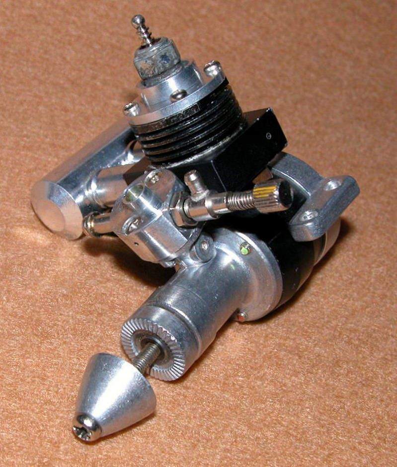
I have an .061 that I purchased a 6x3 prop for based on instruction sheet that came with motor. The hole in the center is bigger than the screw that holds it on. Can I just use brass tubing to make a bushing to fit or is there any commercial nylon spacers available? The screw that holds the prop on is the same as that of an .049 cox. I am also having difficulty locating a pressure fitting for the muffler. Any suggestions? I know Cox has props that fit their shafts, but someone has to have run into this issue and resolved it. The prop I have is an APC sport 6x3.
 03-17-2018, 11:20 PM
#2

Join Date: Jul 2005
Location: Upper HuttWellington, NEW ZEALAND
Posts: 1,601
Likes: 0
Received 1 Like
on
1 Post
Actually the G-Mark prop screw is 3mm metric: M3x0.5 which makes it a bit smaller than the Cox 049 prop screw which is 5-40 thread-and 1/8" diameter. There are plastic bushings available from APC that can be used for bushings-but brass tube is just as effective-you may have to telescope a couple of sizes to match the prop ID with the screw OD. A 6x3 is a good match for the G-Mark-which peaks around 19, 000-so about 3000rpm less than a Cox TD 049-the APC with its relatively narrow blades is a very good match. If you haven't run it yet-my advice [and I own about 6 of them!] is to run it in gently-these are nice engines-but they take a significant amount of running in compared to a Cox. If you give it just a token Cox style run in, you will be disappointed with it in use.
ChrisM
'ffkiwi'
ChrisM
'ffkiwi'
03-22-2018, 11:14 AM
#3
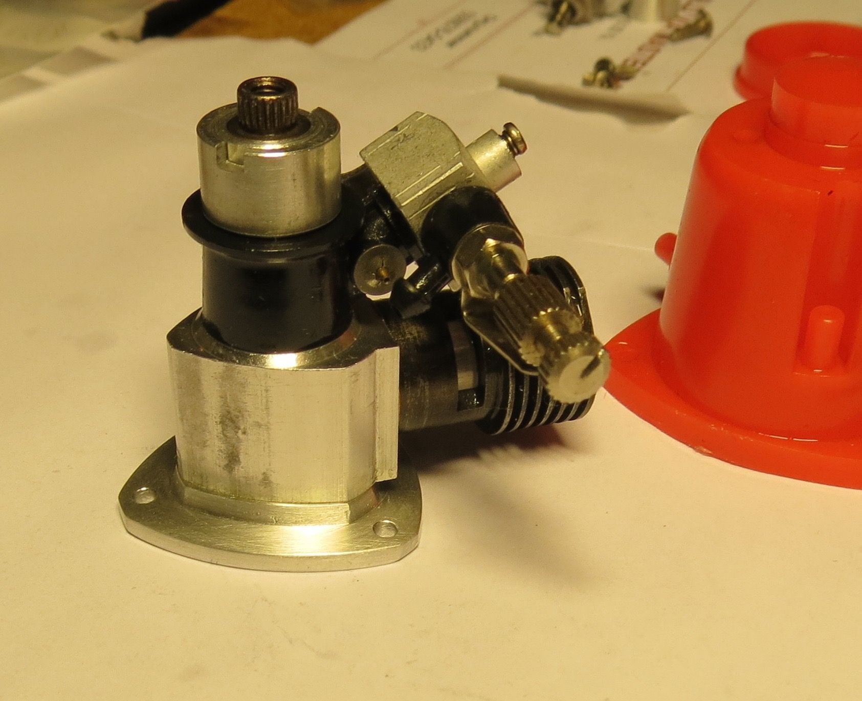
So I fired it up today after getting the prop bushing thing figured out. If only for a moment just to hear it run. I noticed that when spinning the motor after I killed it that it was blowing bubbles around the right side of the rear plate (as looking at the front of the motor). It seemed to run fine for the short bit I ran it. Wondering if I need to make a new gasket for it or should I just let it soak in the fuel/oil and it will swell slightly and seal. It was a never run motor but had been mounted. In regards to mounting would I be better off using a radial mount or the beam style nylon mount. I noticed that the beam style that it was mounted to had to be modified slightly to work with the triangular crank case. A radial mount would actually let me mount the motor closer to the firewall but I have read that the plane (Sig Herr Cloud Ranger) tends to be tail heavy anyway. I also noticed that 2 of the 4 stock firewall holes in the beam mount will be blocked by the motor. Just an obvious newbie looking for some answers.
03-23-2018, 08:14 AM
#4


Join Date: Oct 2002
Location: Chilliwack, BC, CANADA
Posts: 12,425
Likes: 0
Received 22 Likes
on
19 Posts
A leak like that is never a good thing. It'll be too slow a leak to make a lot of difference when running but it could be rapid enough to make starting a little more difficult. Let the gaskets work with the oil for a day or three but then I'd suggest trying to tighten the rear cover in case it's come loose. Don't try to tighten super hard but a firm twist of around 6 foot-lbs would not be out of place. If you're not sure about torque amounts 6 foot-lbs would not be enough to open a new small jar of pickles or jam. We're talking very fine aluminium on aluminium threads so you don't really want to go with much more than that.
03-24-2018, 07:20 AM
#5
The stock paper gasket is very thin, so my guess is that it has broken when someone removed the backplate.
You can quite easily cut a new one from thin gasket material, or simply use a regular thicker paper. Some even use the regular brown envelopes as gasket material.
You can quite easily cut a new one from thin gasket material, or simply use a regular thicker paper. Some even use the regular brown envelopes as gasket material.
04-28-2018, 07:19 PM
#7
so I got all but the 15 minute varied throttle break-in done today. This is a sweet little running motor. A few observations;
1. the muffler does not seal and is only slightly better than an open cylinder as far as oil flying everywhere.
2. On my test stand I found I need a pressure tap with a solid tank as it was choking on the final leg of static running. When I kept pressure in the tank it picked up and ran well again.
3. This thing spews alot of oil. Granted I was very rich on the first run, and slightly less rich on the second.
4. These little motors can use a heck of a lot of fuel if they are really rich. about 7-7.25 ozs in a twenty minute run, about 6-6.5 in the second run, and when it was set the way I would fly it it used about 4.5ozs in 20 minutes.
5. with an APC 6x3 sport prop I was getting about 14500-14600 rpm's WOT on the last run. I will research to see if that is in the ballpark or not. Guessing it should be up there a bit more, and it may pick up a few RPM's as it loosens up more.
Has anyone done anything with the muffler to get it to seal up a bit better or am I doing something incorrect? The index tab is lined up and the screw holding the two halves together is tight. Maybe expecting too much.
Still looking for a radial mount for one.
04-29-2018, 07:54 PM
#8

I have both .03 and the .06 pressure taps on the mufflers help for sure.
Shame they did not make a better effort with the muffler fit but it does
help so worth using. I don't recall the data on the .06 they are no rpm
beast but do make usable power for a RC project.
Shame they did not make a better effort with the muffler fit but it does
help so worth using. I don't recall the data on the .06 they are no rpm
beast but do make usable power for a RC project.
04-30-2018, 02:16 PM
#9
I have sealed the muffler against the crankcase, and the two muffler halves, with hightemp silicon on some engines and that will help a bit with all the oil.
With the stock muffler, 10% nitro (and 20% all castor) it will spin a graupner 6x3 prop at around 14500rpm, so it sounds like your engine is right in the ballpark of their performance.
NoNo Fulton saw a bit higher numbers, but he also had the muffler mounted upside down(!):
With the stock muffler, 10% nitro (and 20% all castor) it will spin a graupner 6x3 prop at around 14500rpm, so it sounds like your engine is right in the ballpark of their performance.
NoNo Fulton saw a bit higher numbers, but he also had the muffler mounted upside down(!):
Last edited by Mr Cox; 04-30-2018 at 02:22 PM.
04-30-2018, 07:10 PM
#10
Lol I noticed that the muffler was on the other side. Also that video was the basis for my question about top speed. Learned a valuable lesson this past weekend, I was doing the final leg of break-in and it was windy as heck out. I was at the end of the 15 minutes and watched a gust of wind blowing a bunch of dirt toward the motor. I instinctively reached for the carb throat to keep the dirt from going right in, we�ll there was a prop between my fingers and the carb. Probably could have used stitches, but I had some steri-strips handy. Moral of the story, these little buggers can do some damage!
05-01-2018, 10:51 AM
#11
Yes, you do have to be careful, those APC props a shaped like blender blades....
A good habit is to always stand behind the engine while it is running, that saves you from a thrown prop, or prop-blade, and also from trying to reach through the prop-arc.
I wish you a speedy recovery!
A good habit is to always stand behind the engine while it is running, that saves you from a thrown prop, or prop-blade, and also from trying to reach through the prop-arc.
I wish you a speedy recovery!
02-06-2019, 08:48 PM
#12
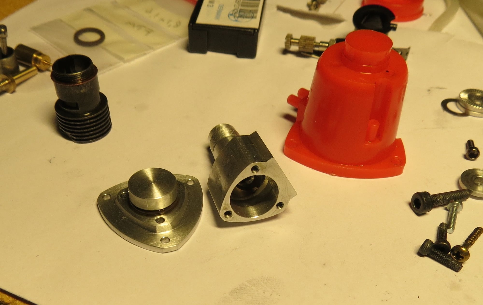
so I have had absolutely no luck on finding a 1/2a size exhaust pressure fitting. I am probably going to build my own radial mount out of aluminum bar stock as well as I have not been able to come up with anything there either.
02-06-2019, 09:11 PM
#13
Join Date: Jul 2005
Location: Upper HuttWellington, NEW ZEALAND
Posts: 1,601
Likes: 0
Received 1 Like
on
1 Post
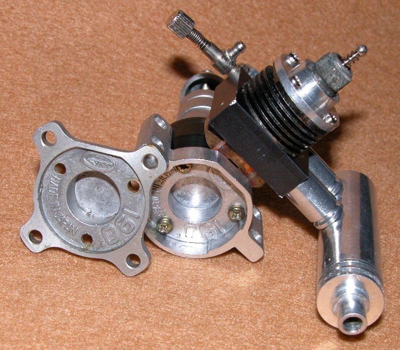
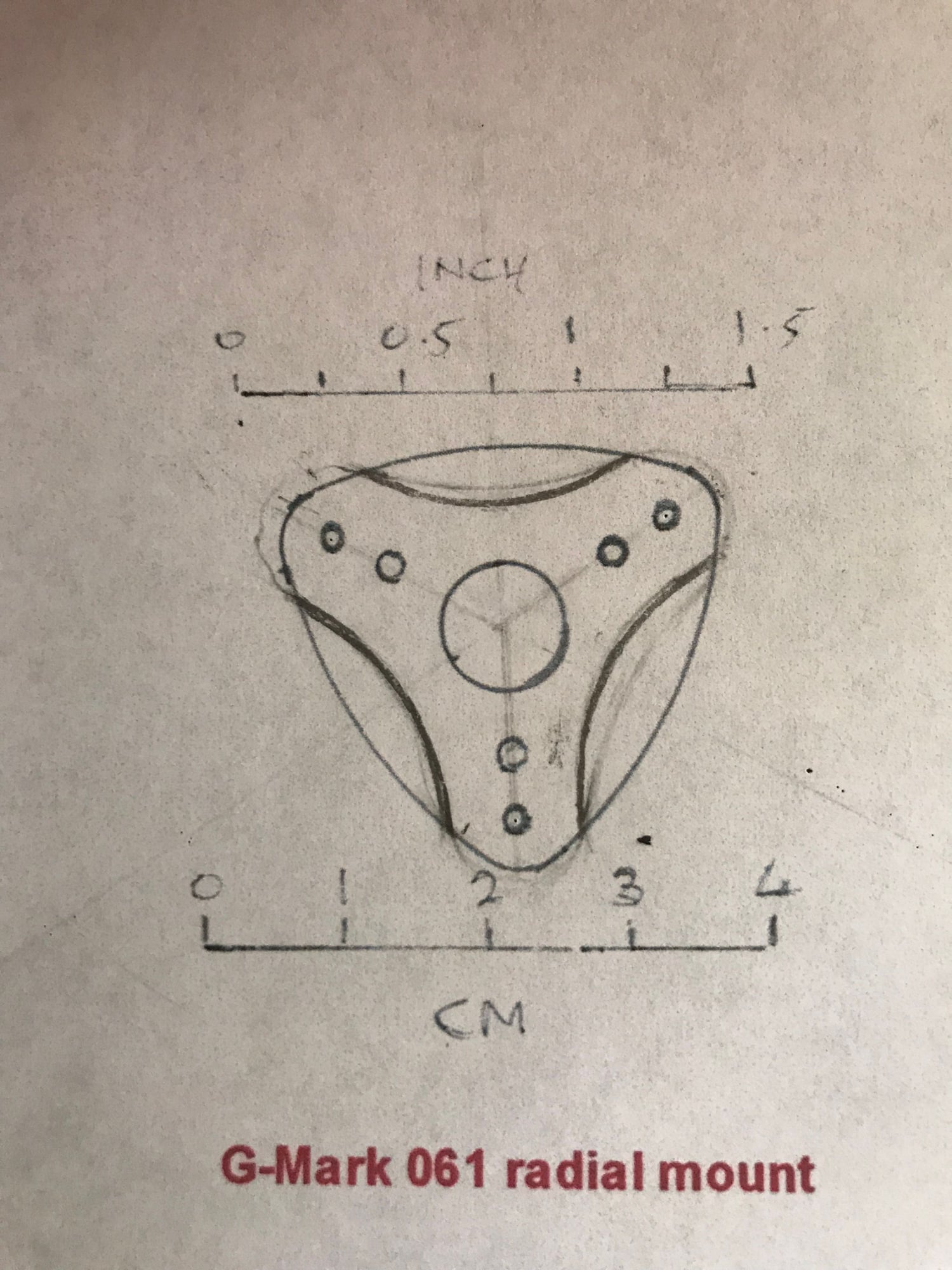
The G-Mark ..061 radial mount is easily copied-it is simply flat aly sheet attached to the engine with the original backplate screws...the originals are not very common-nor are the plastic ones for the .03-but not hard to create a copy. I will draw my one up, and scan it (with a suitable rule included) so you can print it out full size as a template. The UK's Mike Billington did the only published test on the G-Mark 061-published around 1985 in 'Aeromodeller'.....to the best of my knowledge there has never been one published on the .03. If you have the means-and the inclination, Billington indicated that the engine responded well to more nitro-but needed cylinder shimming to increase the exhaust timing to properly benefit from this-and likewise an adjustment to the head insert depth. Reading between the lines-the head itself could benefit from a bit better design-either to take an insert, or a Nelson or turbo plug.
ChrisM
'ffkiwi'
02-06-2019, 09:28 PM
#14
I thought at one time I had found a 4-40 pressure tap from radical rc, but I�ll be darned if I can find it again. The drawing of the mount would be amazing. So the screws are long enough with say 1/8� aluminum to use stock ones? There would be a countersink in there the depth of the screw heads, so it wouldn�t actually be that much.
02-07-2019, 12:59 AM
#15
Join Date: Jul 2005
Location: Upper HuttWellington, NEW ZEALAND
Posts: 1,601
Likes: 0
Received 1 Like
on
1 Post
OK here it is-very rough. The material is 2mm thick alloy-the centre hole is 10mm diameter, and the inner 3 holes in a triangle match the backplate mounting screw location. The mount has been stamped or edm cut, judging by the edge marks. A thin slice 2-2.5mm thick from a piece of 35mm round bar would give you a suitable starting point. All holes are 2.8mm ID. These inner holes are counterbored 4.2mm (11/64" nominal) on the firewall face of the mount to provide clearance for the screw heads [this need not be done if you use countersunk screw heads...in which case obviously you countersink the mount to seat the screws flush. Obviously-depending on the thickness of your radial mounting flange you may have to use longer backplate securing screws....
ChrisM
'ffkiwi'
ChrisM
'ffkiwi'
02-09-2019, 10:06 AM
#16
Thank you very much ffkiwi!!!
i shaved a bit off the mount drawing by making a crescent indentation between the ears. It seems that the triangular mount is way over engineered. The thought crossed my mind to shave the beam mount ears off the crankcase to save some weight, but it won�t be that much and with the possibility of that being designed into the case for structural support I decided for now to leave it alone.
i shaved a bit off the mount drawing by making a crescent indentation between the ears. It seems that the triangular mount is way over engineered. The thought crossed my mind to shave the beam mount ears off the crankcase to save some weight, but it won�t be that much and with the possibility of that being designed into the case for structural support I decided for now to leave it alone.
02-09-2019, 11:02 AM
#17
The drawing looks good for the .061, one just have to be careful with having enough bolt length for the threads in the crankcase. I wouldn't bother with removing the regular engine mounts, there is hardly any weight to save there anyway.
For my .03 engine I only had the tank mount, and the plastic is very flexible. The engine vibrates quite a lot at high rpms, and the carb wears out etc.. Here I had to make a new complete backplate, a lot more work than what is needed for the .061, but it is fairly straight forward to do too:
For my .03 engine I only had the tank mount, and the plastic is very flexible. The engine vibrates quite a lot at high rpms, and the carb wears out etc.. Here I had to make a new complete backplate, a lot more work than what is needed for the .061, but it is fairly straight forward to do too:
02-09-2019, 05:28 PM
#18
Join Date: Jul 2005
Location: Upper HuttWellington, NEW ZEALAND
Posts: 1,601
Likes: 0
Received 1 Like
on
1 Post
Thank you very much ffkiwi!!!
i shaved a bit off the mount drawing by making a crescent indentation between the ears. It seems that the triangular mount is way over engineered. The thought crossed my mind to shave the beam mount ears off the crankcase to save some weight, but it won�t be that much and with the possibility of that being designed into the case for structural support I decided for now to leave it alone.
i shaved a bit off the mount drawing by making a crescent indentation between the ears. It seems that the triangular mount is way over engineered. The thought crossed my mind to shave the beam mount ears off the crankcase to save some weight, but it won�t be that much and with the possibility of that being designed into the case for structural support I decided for now to leave it alone.
I suppose G-Mark were trying to keep a certain 'house style' with the radial mount...similar to the .03 [which actually preceded this version of the .061]...though the .03 mount was plastic. Of course the original 061 was a rather ugly clunky thing devoid of much in the way of aesthetics....which is not to say it wasn't well made....but bulky and heavy for the power it delivered...
ChrisM
'ffkiwi'
 02-09-2019, 10:59 PM
#20
Join Date: Jul 2005
Location: Upper HuttWellington, NEW ZEALAND
Posts: 1,601
Likes: 0
Received 1 Like
on
1 Post
No reason at all why that ''diet version' approach wouldn't work-I'd try and use some aerospace grade alloy sheet for if I were you though-.....I've just measured up a backplate screw-I make it about 2.2-2.3mm....very odd! M2.5 is too big, M2 too small-you might have to be a bit careful with your material thickness so you can use the original backplate screws....as these seem to be an obscure thread...and being Japanese-almost certainly a metric one-but probably JIS rather than the international ISO range of metric....I'm guessing they're probably M2.3-which is a genuine metric thread-but a very uncommon one! To make matters worse there is a fine thread and a coarse thread variant: M2.3x 0.4 and M2.3x 0.45...so the chances of being able to source slightly longer machine screws (the originals are 5mm thread length) in those thread variants are virtually zero....leaving you the option of either keeping the originals or tapping out the crankcase holes to take a US size-2.56 for example is fairly close in size [and the thread pitch is .456mm....so if the originals are M2.3x0.45, your 2-56 is almost going to fit if you need a longer screw to secure the radial mount....I guess it becomes your call depending on how thick you make the radial mount....and whether you counterbore for the screw heads, like in the original...
ChrisM
'ffkiwi'
ChrisM
'ffkiwi'
03-20-2019, 11:07 AM
#21
I got a piece of 1/8" 6061 t6 to use for the radial mount. There certainly isn't going to be an abundance of thread left after counterboring, but it appears to me that it will be adequate. The 1/8" is about 2.98mm thick so I am thinking I will do diet version as it is quite a bit thicker than original. The other option is to sand the piece down (dont have access to a mill) to thin it out a bit and just go with original design as posted by ffkiwi. I am not sure how to proceed on this yet, as I only have a drill press and hand tools. The counterbore is my biggest challenge at this point with making the bottom 90 degrees for the screw to seat against firmly. any suggestions?
03-20-2019, 12:10 PM
#22
Join Date: Jul 2005
Location: Upper HuttWellington, NEW ZEALAND
Posts: 1,601
Likes: 0
Received 1 Like
on
1 Post
I got a piece of 1/8" 6061 t6 to use for the radial mount. There certainly isn't going to be an abundance of thread left after counterboring, but it appears to me that it will be adequate. The 1/8" is about 2.98mm thick so I am thinking I will do diet version as it is quite a bit thicker than original. The other option is to sand the piece down (dont have access to a mill) to thin it out a bit and just go with original design as posted by ffkiwi. I am not sure how to proceed on this yet, as I only have a drill press and hand tools. The counterbore is my biggest challenge at this point with making the bottom 90 degrees for the screw to seat against firmly. any suggestions?
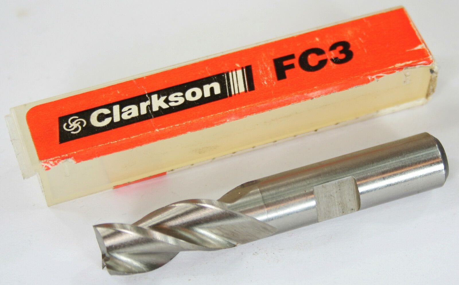
are you familiar with FC3 cutters? these are combination end mill/slot drill disposable cutters-which are much cheaper than either endmills or slot drills-and available in a range of metric and imperial sizes. One of these in the right size would do the job-the only two alternatives would be a D-bit.....and you dont have the equipment to make one-or one of those 'fishtail' carbide burrs-if you can find one that matches the screw head diameter. Whatever you use for the job-make sure the drill chuck is really tight-drills are not very good being pressed into service for milling as there is no means of axial limiting the cutter movement in the chuck, as there is on a proper mill.
Good luck with it...
ChrisM
'ffkiwi'
 04-02-2019, 10:39 PM
#23

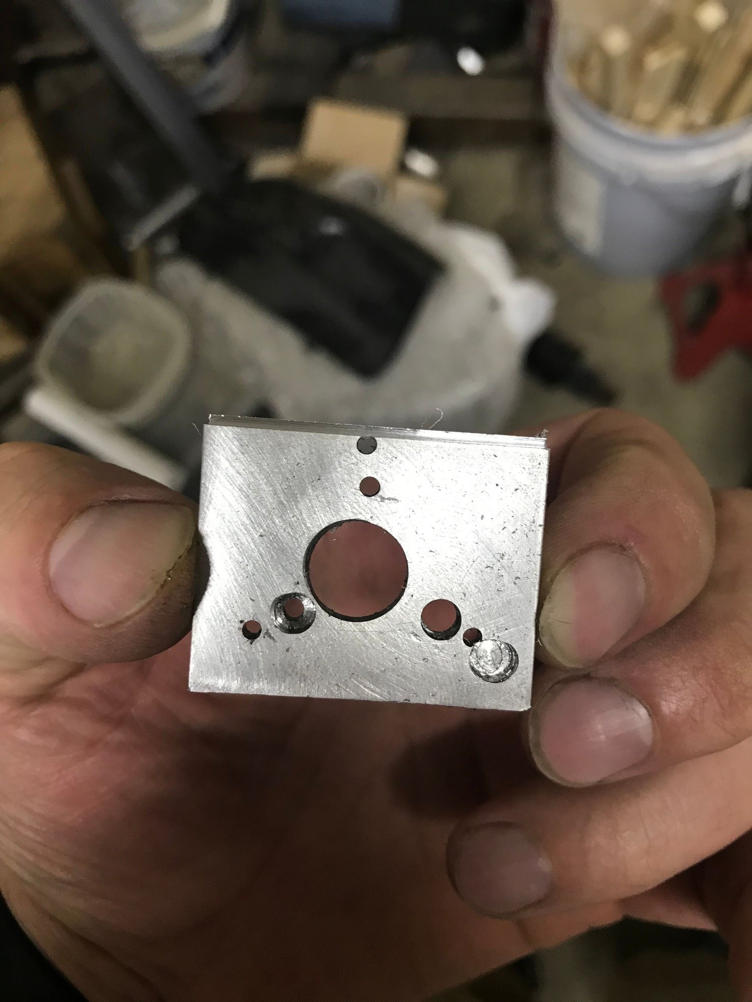
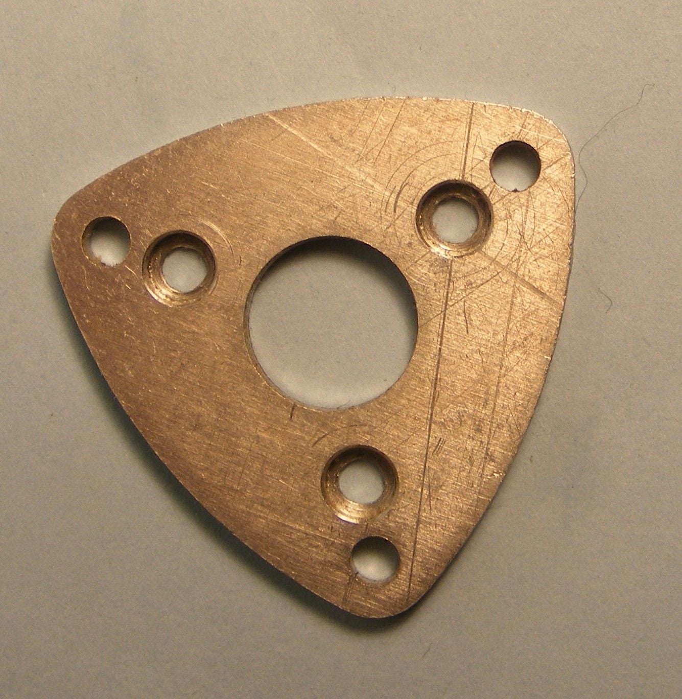
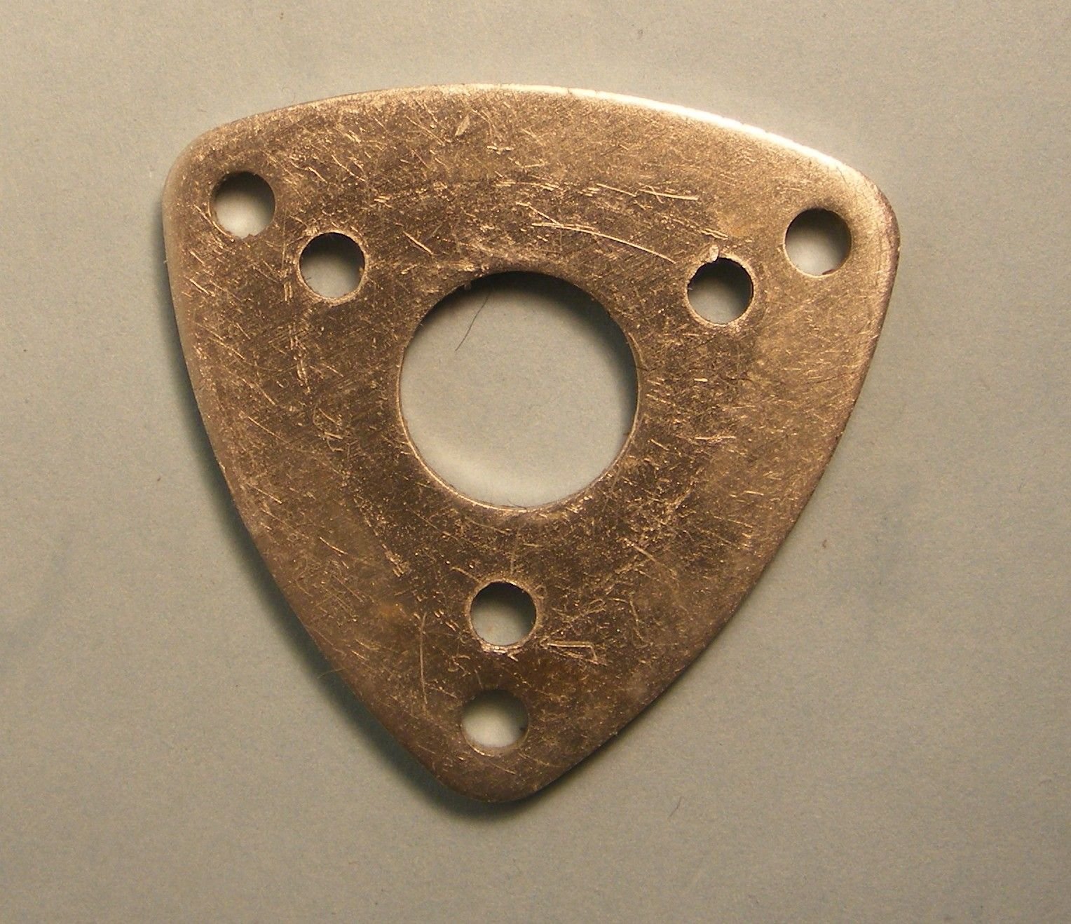
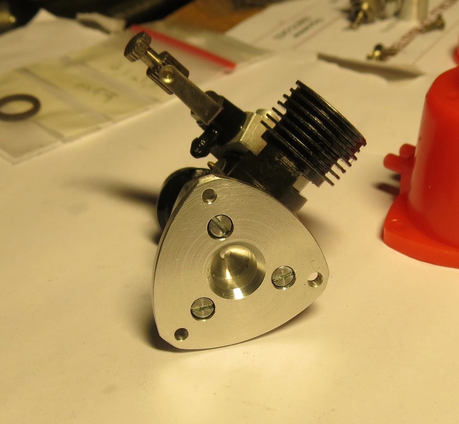
Her is my first try and the final draft. I still need to cut some excess off. The recess holes are 2.24 deep with total plate width of 2.99mm. I�m thinking about thinning the plate out a bit but we�ll see.
04-03-2019, 11:37 PM
#24
I have a CNC aluminum backplate mount in the mail, if it becomes a product I will post a link to it here.
I am to do an evaluation on it along with another add on part. The goal is to gain another 1k rpm out of the stock
engine with a 4.5x2 prop. Will post some pics and the bench test.
I am to do an evaluation on it along with another add on part. The goal is to gain another 1k rpm out of the stock
engine with a 4.5x2 prop. Will post some pics and the bench test.
04-04-2019, 09:01 AM
#25
I have a CNC aluminum backplate mount in the mail, if it becomes a product I will post a link to it here.
I am to do an evaluation on it along with another add on part. The goal is to gain another 1k rpm out of the stock
engine with a 4.5x2 prop. Will post some pics and the bench test.
I am to do an evaluation on it along with another add on part. The goal is to gain another 1k rpm out of the stock
engine with a 4.5x2 prop. Will post some pics and the bench test.