


Ply Rolled Fuselage Part Deux - 1/2A " Mini Skorch "
 04-11-2015, 12:27 PM
#476

Thread Starter

Yea I have parked some info for safe keeping in the thread here I will have to source some high temp epoxy at some point.
Should be a major weight savings for small engine use.
Should be a major weight savings for small engine use.
 04-19-2015, 05:43 PM
#477
Thread Starter
Collecting data
The Killer TD .049 - Cox RC carb
I am breaking in the engine in the air
2nd flight APC 4.5 x 4
22,044 rpm in the hand 25% nitro
best pass at 24,160 rpm needle is set bit rich.
67 F. winds 6 to 9 mph
After a few more runs I expect a fully broken in engine getting about 25k needle peaked.
3rd flight APC 4.75 x 4 - Galbreath / Nelson plug
20,873 rpm in the hand 25% nitro
22,287 rpm cross wind and 23.94k down wind
9 to 12 mph winds - temp 78 F Humidity 80%
Previous TD .049 - Cox RC carb - Cox High Comp plug
APC 4.75 x 4 (no data with the 4.5 x 4)
19,380 rpm in the hand 25% nitro
21.4k rpm cross wind 23.3k down wind.
Winds about 4 to 6 mph per hourly weather check. 74 F.
Last edited by Pond Skipper; 04-19-2015 at 09:21 PM.
 04-19-2015, 07:53 PM
#479
Thread Starter
Looks like the new Killer TD is winning the race static on the 4.75D is up 1,493 rpm - in the air up to 91mph theoretical.
Will go back to the 4.5 x 4 now that the engine is broken in to see what it will top out at think 24.8 to 25k ish 95 mph.
On a side note the plane can hang on the 4.75 prop rudder has full authority. The throttle response is great with the reasonable low idle now.
I was able to enter a slow climb to full vertical applying near and at full throttle to hang on the prop there was a slight climb if allowed.
I also did some knife edge passes down wind its getting pushed - into the wind its holding the nose up till time to turn around.
Spins with rudder, ailerons and elevator are slow easy to follow on low rate and positive snaps on high.
low pass on landing I set the prop to windmill and lock parallel to the ground it nearly there, the piston weight has found a balance
the pic will help me to set it up on the sweet spot.
Last edited by Pond Skipper; 04-19-2015 at 08:02 PM.
04-24-2015, 01:31 AM
#480
Thread Starter
Odd that I have just been running a real great engine on the Skorch I would be removing the Killer TD piston and cylinder lol but must make way for the tuned pipe.
So I have the RC.050 piston / cylinder with the performance crank and the Cox carb with rear back plate KK pressure tap.
I bought some small Robart 1/16th pressure type T couplers so I can spot when the tank is full and avoid flooding the crank case.
I will use a TD high compression glow plug to start I may have to slap on a standard plug if the rpm's are excessive.
Will tach the engine Friday and see what the static reads are and the CG is gooood whew the mass of the silicone coupler
helped offset the rearward pipe weight. Decided to park the pipe to the side for a few good reasons to divert goo from the tail
level the pipe to avoid oil build up and to offset torque roll on launch.
All up weight is 12.46oz not bad for a 5ch 1/2A plane with a tuned pipe!
04-25-2015, 02:51 AM
#482
Thread Starter
Collecting data
The Killer TD .049 - Cox RC carb
I am breaking in the engine in the air
KB Galbreath / Nelson plug
#1 cylinder 2 bypass ports 1 boost flute per port
2nd flight APC 4.5 x 4
22,044 rpm in the hand 25% nitro
best pass at 24,160 rpm needle is set bit rich.
67 F. winds 6 to 9 mph
3rd flight APC4.75 x 4- Killer TD .049
20,873 rpm in the hand 25% nitro
22,287 rpm cross wind and 23.94k down wind
9 to 12 mph winds - temp 78 F Humidity 80%
Stock TD .049 - Cox RC carb - Cox High Comp plug
APC 4.75 x 4 (no data with the 4.5 x 4)
19,380 rpm in the hand 25% nitro
21.4k rpm cross wind 23.3k down wind.
Winds about 4 to 6 mph per hourly weather check. 74 F
Profi Tuned Pipe TD RC .050 non SPI - 1st bench test
Tarno Carb, Cox buggy header pipe with half moon 3/4th around brass shim to block 1 exhaust port
#5 cylinder 2 bypass ports and 2 boost flutes per port -1 shim HC Cox Plug - KK pressure tap
Tad rich approx 85% to optimum break in mode with new #5 cylinder
- Idle with Tarno carb 11.786 rpm APC 4.5 x 4
- vid recorded 20,996 rpm on the pipe best noted 21,370 rpm 25% nitro
Anticipate 22k +/- static best NV setting - will add one more shim
https://www.youtube.com/watch?v=1BQN...ature=youtu.be
https://www.youtube.com/watch?v=1BQNs7cQl_0&feature=youtu.be
Last edited by Pond Skipper; 04-25-2015 at 03:25 AM.
04-25-2015, 11:08 PM
#483
Thread Starter
I need more silicone tube I ordered to set up the plane for best pipe length for now I rigged up a temporary way to sort out the rear pump.
Using some additional aluminum tube and forming it to go from round to square I have a transition to the cox exhaust deflector.
I fired up the engine and slide Profi pipe in both directions till the engine found its best note. Will do another test vid #2 on Sunday to show the difference in rpm.
Total adjusted length as shown in the pic 10.75in to the cylinder wall.
04-26-2015, 09:02 AM
#484
Thread Starter
Extended header pipe total length 10.75in dropped rpm down to 7,504 -8.52k average.
The top end 19,622 90% best needle 1 shim rpm is less than the original set up.
I noted that total pipe and header length at 11.25" was increasing low end and decreasing the top end.
For swinging a 6 x 3 the added torque may be worth it.
Tried low compression glow plug on one shim this resulted in lower rpm and idle.
Last edited by Pond Skipper; 04-26-2015 at 04:56 PM.
04-26-2015, 03:04 PM
#485
Thread Starter
Ok uploaded the vid - ramps good sounds like a little tuned pipe, wonder what a TD .020 would sound like ")
https://www.youtube.com/watch?v=bTpOqmAAf3o
https://www.youtube.com/watch?v=bTpOqmAAf3o
https://www.youtube.com/watch?v=bTpOqmAAf3o
https://www.youtube.com/watch?v=bTpOqmAAf3o
04-26-2015, 09:19 PM
#487
Thread Starter
A few months back I bought some cylinder shims to raise the exhaust ports up effectively raising the transfer ports up and speeding up the exhaust timing. I figure if the the high compression head and one shim is used the engine would some wiggle room before the ignition timing gets too retarded and low on compression.
I dont have a degree wheel made up to check stock timing of a non SPI engine vs a SPI. Checking on the net I saw no collected data. If you have a wheel and a TD laying around I would imagine odds are good its a SPI cylinder if you don't mind checking you will be the first person that comes up on a search to actually post the numbers.
I dont have a degree wheel made up to check stock timing of a non SPI engine vs a SPI. Checking on the net I saw no collected data. If you have a wheel and a TD laying around I would imagine odds are good its a SPI cylinder if you don't mind checking you will be the first person that comes up on a search to actually post the numbers.
Last edited by Pond Skipper; 04-26-2015 at 10:40 PM.
04-27-2015, 12:44 AM
#489
Thread Starter
It was interesting to see when using the longer header how it sucked out too much fresh fuel while the transfer ports where still open in turn it delayed the divergent cone leaving unspent fuel in the pipe as each cycle past an increased puddle started forming in the convergent / divergent area of the pipe otherwise known as the cone or belly. Last effort shown on vid at 19.662 rpm with a hard to fathom 328 cycles per second wasn't puddling enough to noticed nor spraying fuel as when the pipe was at 11.25" total length or approx 57 mm of added header - the obvious reared its ugly fuel wasting head when the rear tail feathers and fuselage had a spray of notable clear fuel drops rather than just oil.
My current best readings has the header pipe extended 14 mm - the longer silicone tube will allow me to try further out up to 35 mm range at 40 mm the engine was loosing rpm (less 1.334 rpm). I do need a cleaner constant matching interface to the engine, I have some options for that. All in all its been fun to mess with thus far.
My current best readings has the header pipe extended 14 mm - the longer silicone tube will allow me to try further out up to 35 mm range at 40 mm the engine was loosing rpm (less 1.334 rpm). I do need a cleaner constant matching interface to the engine, I have some options for that. All in all its been fun to mess with thus far.
04-27-2015, 01:42 AM
#490
Thread Starter
If the TD .050 timing is similar to the TD .010 of 240 deg duration and the pipe from the center of the cone to the manifold in this case the Profi plus my add on has it at 6.5in and the engine is currently at 20,992 rpm we can calculate the pipe length from cone to manifold for near optimum length.
Say rounded 21000 x 6.5in divided by 240 for 568.75
If target unloaded rpm is 23000 than 240 x 569 divided by target 23k give you a center cone to manifold ratio of 5.94 inches.
I am off by half ish inch currently - but this simple math does not account for the effect of nitro burning the ignited methanol at a faster rate.
04-27-2015, 03:16 AM
#491
It is very easy to put a degree wheel on the prop axis and measure the timings.
In the figure above, the TD .010 has an exhaust duration of 120�, not 240�, so it would be a very modest timing for tuned pipes...
In the figure above, the TD .010 has an exhaust duration of 120�, not 240�, so it would be a very modest timing for tuned pipes...
04-27-2015, 06:27 AM
#492
Thread Starter
120 divided by 240 for 120 - do you have a deg. wheel handy if so when you have a moment post your findings 
Here is the formula I used:
TUNING THE EXHAUST SYSTEM
Pipe length is decided by rpm, exhaust timing and speed of sound within the exhaust system. The last part should remain almost the same whatever you do to the exhaust timing or rpm.
1. If you increase the exhaust timing and rpm stays the same then pipe length is longer.
2. If you increase the rpm but exhaust timing stays the same then the pipe length has to be shorter.
If you can measure the rpm of your motor and exhaust timing, then you can use a simple calculation to show how much you need to change the pipe length when altering ex timing and rpm. Here are some simple calculations for gas engines where the exhaust gas temperature is not affected by nitro content and varying fuel settings.
(For these calculations you can measure the pipe length between whatever points you want to, but the norm is from plug to widest part of cone.)
Pipe length from manifold face to widest part of front cone. = L
Exhaust timing = E
Constant = K
rpm =R
If rpm is 15,000, exhaust timing is 175degrees (duration) and pipe length is 13" then....
Firstly you work out the constant for your set up. So...
K = R x L K = 15,000 x 13 = 11.14"
------------------ -----------------
E 175
In this example that would give a K number of 1114 and as I wrote before, K will remain the same whatever you do...
If you want the engine to rev at 16,000, the equation changes to...
L= E x K therefore L = 175 x 1114 = 12.18
------------- ---------------
R 16,000
This would make the new pipe length 12.18" or 309mm.
If you wanted to increase exhaust timing to 180 degrees and run at 17,000rpm then the length L would be 11.79" or 302mm.
04-27-2015, 07:19 AM
#493
Attached is a degree wheel that you can print and glue to a piece card-board or plywood. Clamp a piece of music wire in the mounting lugs as an indicator.
Also attached are some "theoretical calculations" and a few of my own data points, "Theory" will give you the principles and guideline, then you have to tune from there.
04-27-2015, 08:17 AM
#494

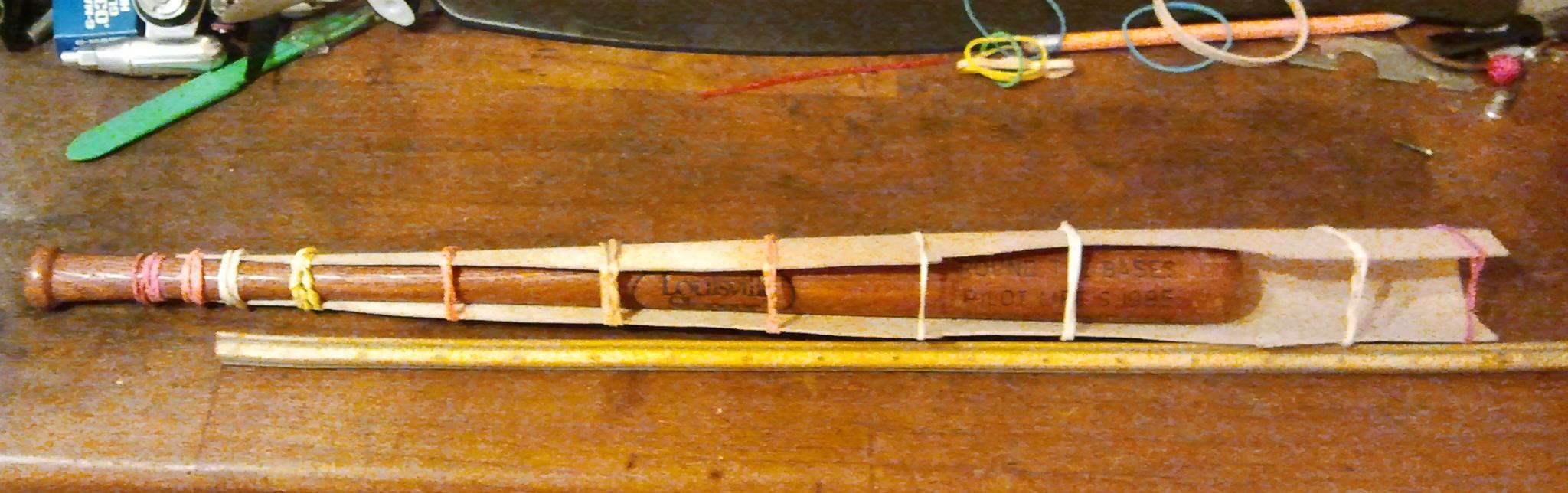
I had used a PVC pipe on the first build this one I used a miniature Louisville Slugger Baseball Bat approx 1/4 scale. The bat has a nice continuous taper allowing less manipulation then the first build. Using hot water I have allowed the ply to dry overnight for 24hrs.
04-27-2015, 07:55 PM
#495
Thread Starter
Thank you Kris I printed out the wheel and used it this evening = )
Hi RGB thank you,
Yes that lil bat paid off for a real use for once, I have kept it for some years now it was my fathers. Could use a full size or pee wee bats
to do 20 to 90 size planes a simple nice straight fuselages.

Hi RGB thank you,
Yes that lil bat paid off for a real use for once, I have kept it for some years now it was my fathers. Could use a full size or pee wee bats
to do 20 to 90 size planes a simple nice straight fuselages.
04-28-2015, 01:16 AM
#496
Thread Starter
Ok I can press forward with testing on Tues. the 7mm silicone came in.
I like it had three set grooves for zip ties much more secure.
I have 8.5in from center cone to cylinder ish if you count the center of the piston to work with.

I like it had three set grooves for zip ties much more secure.
I have 8.5in from center cone to cylinder ish if you count the center of the piston to work with.
04-28-2015, 12:25 PM
#497
Thread Starter
Found another formula seems to provide reasonable pipe lengths
Lt = (Eo x Vs) / N English OR (83.3(Eo x Vs)) / N Metric
Where:
Lt = tuned pipe length, in inches or millimeters
Eo = exhaust open period, in degrees
Vs = wave speed (1700 ft/sec or 518.16 Meters/sec at sea level)
N = crankshaft speed, in RPM
example, we have an engine that will turn 25,000 RPM. We calculate that we will only use 20,000 of those RPM's and our exhaust duration is 180 degrees. Then we substitute in the formula:
Lt = (180 x 1700) / 20,000 OR (83.3(180 x518.16))/ 20000
Lt = 15.3 inches OR 388.46 mm
The deg wheel shows the .049 to be at 120 deg.
120 x 1700 / 23800 (unloaded est. goal) for pipe length of 8.57
So looks like the silicone adapter will get me where I need to be unloaded with either the 4.2 x 4 or 4.5 x 4
So next test with the 4.2 x 4 static which will help give some idea how close to a unloaded 4.5 x 4
Last edited by Pond Skipper; 04-28-2015 at 12:27 PM.
04-29-2015, 05:54 PM
#498
Thread Starter
Ok its really getting down to the fine tuning now as it must. The Cox buggy muffler is still being used but it has to be understood how its affecting the system by lieu of the square transition and choke down from 7.5mm to 3.5mm. It acts like a anti -reversion zone limiting back flow of exhaust gases back into the cylinder fooling the pipe in thinking its longer than it is. How much will be known as the numbers come to light in the testing. The current physical length as 8.25 Given a section is part cox muffler acting like a anti reversion zone my guess I am actually at around 8.75in from just behind the threaded collar. I need to simulate unloaded conditions to see / hear and feel that its on the pipe here is the result.
APC 4.2 x 2
120 x 1700 / 24,063 for 8.4777459 (think Im a bit over revved engine was hot as the pipe
wasn't keeping up header with anti reversion est. 8.75
- next will try a 4 x 2.5 to simulate the APC 4.2 x 4 unloaded
Need 204,000 / 8.75 for 23,314 rpm so 4.2 x 4 for 88.3 mph

APC 4.2 x 2
120 x 1700 / 24,063 for 8.4777459 (think Im a bit over revved engine was hot as the pipe
wasn't keeping up header with anti reversion est. 8.75
- next will try a 4 x 2.5 to simulate the APC 4.2 x 4 unloaded
Need 204,000 / 8.75 for 23,314 rpm so 4.2 x 4 for 88.3 mph
04-29-2015, 07:35 PM
#499
I'm surprised to learn that Cox .049s have such low timing.
This helps explain the question I've always harbored about why they have so much exhaust port area. It seems to be the trade off.
The low timing increases the engine's versatility.
As engines get smaller and smaller, the "natural" torque they get from stroke length suffers, so to preserve torque low timing is helpful.
I can now see why blank cylinders were available to experimenters, since going from 120 to 180 is quite a leap.
04-29-2015, 09:38 PM
#500
Thread Starter
On the deg wheel 180 deg is BDC making the crank pin at the bottom of the crank case its hard for me to fathom an engine set up at 180
Last edited by Pond Skipper; 04-29-2015 at 09:50 PM.