


Design KI1603 X-WRAE


 06-04-2017, 03:21 PM
#27
Passed up the opportunity to go flying this weekend in the interest of building... well really drawing... Glad I did because going out flying tends to somehow upset my routine and environment. Now, I have info necessary to create templates for formers/bulkheads.
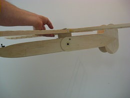
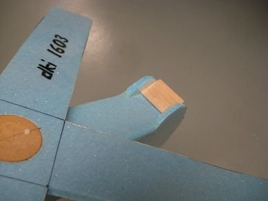
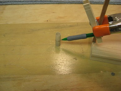
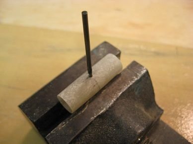
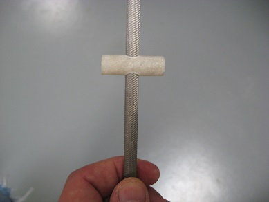
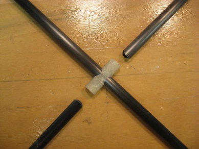
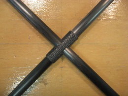
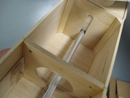
Spent lots of time pondering how to incorporate the release servo into the design and came up with a plan (side view of servo tray location in second pic; top view in forth pic). Plan is to use the carbon rod in third picture as a lock/release pin with localized hard points in corresponding sides.
While I was at it, added corrections and details plus the wing pylon cross section to the top view (last pic).
06-18-2017, 05:03 PM
#28
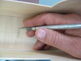
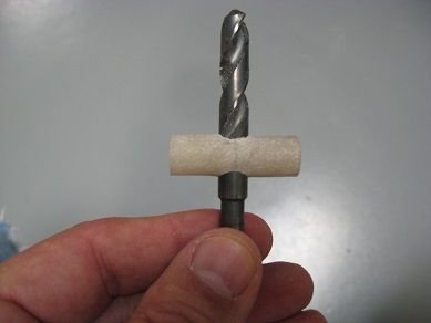
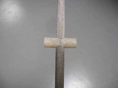
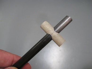
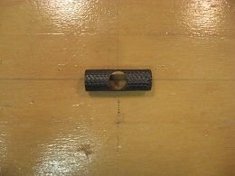
Used some carbon pushrod material to fabricate locking pins - stuffed with wooden swab dowel pin material. Here's something I learned from Trusted Source: turn in drill press while using drum sander chucked up in Dremel results in nice round end...
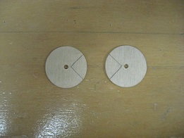
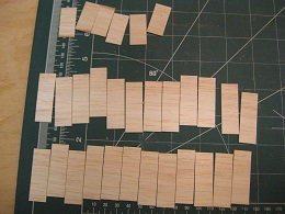
Cut wooden blanks and fabricated six "bearing" hard points for the locking pins - pivot point on block next to disk sander required use of duckbill pliers to turn the parts next to sander. There's probably an easier way to do this but I probably don't possess the skills and/or equipment to tackle it another way.
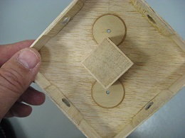
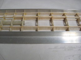
Stacked and aligned right and left fuselage side parts, drilled for, and inserted the bearing hard points.
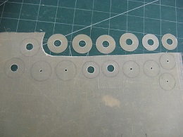
Traced the firewall, formers, and servo tray then attached to appropriate material and rough cut with band saw. Used Dremel and carbide cutter to open up all the big holes, then sanded interiors with drum sander and perimeters with belt/disk sander. Final sanded all parts by hand.
Cut wooden blanks and fabricated six "bearing" hard points for the locking pins - pivot point on block next to disk sander required use of duckbill pliers to turn the parts next to sander. There's probably an easier way to do this but I probably don't possess the skills and/or equipment to tackle it another way.
Stacked and aligned right and left fuselage side parts, drilled for, and inserted the bearing hard points.
Traced the firewall, formers, and servo tray then attached to appropriate material and rough cut with band saw. Used Dremel and carbide cutter to open up all the big holes, then sanded interiors with drum sander and perimeters with belt/disk sander. Final sanded all parts by hand.
Last edited by H5606; 07-23-2017 at 07:39 AM.
07-04-2017, 01:52 PM
#29
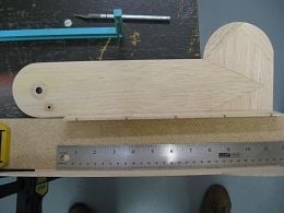
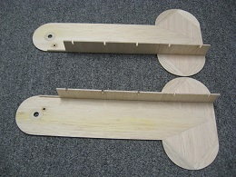
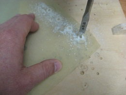
Wasn't happy with the accuracy of hole positions for the three major fuselage parts I drilled originally on the left and right sides, so decided to make a fixture to try to align things better; enlarged holes and "floated" bearing parts with epoxy/baking soda mixture to better align parts...
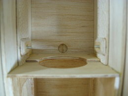
Fabricated center body or "master hinge knuckle interface" using triangle stock in corners and servo tray as spacers to position sides; wrapped 3/32" sheeting around bottom and front with assistance of Windex, white glue, and rubber bands. Located and drilled plywood top for blind nuts and installed; transferred and drilled wing center-section/box for hole mounting locations.
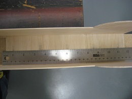
Used 1/64" ply scrap as spacers on either side of center body to space forward fuselage sides and hand sanded all formers on disk-sander table to comply with measurement taken near pivot point. Didn't like the large diameter lightening hole in F-3 so made a new former with a slot for wiring.
Fabricated center body or "master hinge knuckle interface" using triangle stock in corners and servo tray as spacers to position sides; wrapped 3/32" sheeting around bottom and front with assistance of Windex, white glue, and rubber bands. Located and drilled plywood top for blind nuts and installed; transferred and drilled wing center-section/box for hole mounting locations.
Used 1/64" ply scrap as spacers on either side of center body to space forward fuselage sides and hand sanded all formers on disk-sander table to comply with measurement taken near pivot point. Didn't like the large diameter lightening hole in F-3 so made a new former with a slot for wiring.
Last edited by H5606; 07-04-2017 at 01:55 PM.
07-04-2017, 03:57 PM
#30
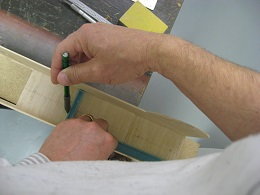
Transferred angles to balsa scrap to set sanding table and sanded in angles on firewall sides to mate up more accruately with fuselage sides. Combination square shows offset.
Tack glued sacrificial, balsa scrap to back of firewall with desired 2 degrees down-thrust at appropriate height and glued firewall to fuselage sides. Placed fuselage above plan view to work over centerline and weighted to immobilize; used square to transpose top of firewall and tack glued firewall in place with CA. Sprayed outsides with Windex to hopefully relieve stresses in wood bending toward firewall.
Fabricated and fit balsa doublers both forward and aft of firewall; applied 30 minute epoxy and clamped to set.
07-20-2017, 03:57 PM
#31
Added details to top view for pylon construction; of all balsa construction - 1/16" base and top with end-grain build-up sort of like an egg carton.
Since the inside of the aft fuse is open, it needs to be Monokoted - inside and out; prepped insides with perforating tool and hair spray and sanded between coats. Spaced out aft fuselage sides from hinge knuckle box and forward fuse with 1/64" shims, measured the separation between sides, and created a spacer block from scrap ply. Added top sheeting to aft fuse sides; had to fit last piece of sheeting between vertical stabs and use some narrow scrap door remains clamped off the end of the bench to reference a flat surface to clear the tails. Since the aft fuse is basically an open box structure (the bottom is open - think very thin "C" cross-section here), there is no real strength and this concerns me as there is such a thin bonding area with the adjacent sheeting. I'm looking at adding a ramp on the inside of the aft end of the fuse - where there is room - and triangle stock to the area between the vertical stabs hoping to try providing more support for the rather flimsy tail-end. Wasn't sure if this ramp would impart a lifting force on the tail driving the nose down so investigating flights with mods to my foamy chuck glider...
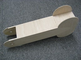
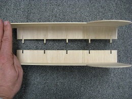
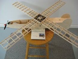
Last three pics showing all the major component parts and assembled airplane of both un-folded and folded modes.
Since the inside of the aft fuse is open, it needs to be Monokoted - inside and out; prepped insides with perforating tool and hair spray and sanded between coats. Spaced out aft fuselage sides from hinge knuckle box and forward fuse with 1/64" shims, measured the separation between sides, and created a spacer block from scrap ply. Added top sheeting to aft fuse sides; had to fit last piece of sheeting between vertical stabs and use some narrow scrap door remains clamped off the end of the bench to reference a flat surface to clear the tails. Since the aft fuse is basically an open box structure (the bottom is open - think very thin "C" cross-section here), there is no real strength and this concerns me as there is such a thin bonding area with the adjacent sheeting. I'm looking at adding a ramp on the inside of the aft end of the fuse - where there is room - and triangle stock to the area between the vertical stabs hoping to try providing more support for the rather flimsy tail-end. Wasn't sure if this ramp would impart a lifting force on the tail driving the nose down so investigating flights with mods to my foamy chuck glider...
Last three pics showing all the major component parts and assembled airplane of both un-folded and folded modes.
Last edited by H5606; 07-21-2017 at 07:54 AM. Reason: Clariity
 07-22-2017, 10:18 AM
#33
Tentative plans for maiden to fly only as an airplane - at least first flight. Hoping this won't all be a humbling, embarrassing, complete waste of time. If the first few flights are completed in airplane-only mode successfully, I'll move on to "pushing the envelope" so to speak.
Successive flights would involve the transformation. Once the switch is flipped and the (hopeful) reconfiguration takes place, guessing it'll be at the mercy of gravity and winds because there'll be no controllability or undoing the reconfiguration. After the switch is initiated, might as well turn transmitter off, collapse the antenna, and put the Tx in the case, as nothing can be done to alter the mode after this "point of no return". Would be nice though, if I can figure out how to "collectively" pitch the wing panels at the end of the descent mode - like doing an auto in a helicopter - to sort of "flare" the arrival (or impact)...
Pics of careful, patient surgery to separate the fwd fuse into halves for tank and throttle servo access using the saw blade removed from an X-Acto spine and cut using bulkheads as a guide - a technique suggested by Trusted Source. Too many times cross-cutting balsa results in less than desirable tearing out of the grain. Reasonably happy with the results here though... Previously made horizontal cuts - easy, 'cause they were grain-wise - with a #11 blade from F-2 fwd to F-2 rear. Also salvaged magnets from a foamy discard to possibly use as positive locking means when airplane folds up. Took note that attraction interaction takes place at around 1.5".
Last edited by H5606; 07-23-2017 at 07:28 AM.
08-04-2017, 03:48 PM
#34
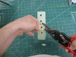
Processing forward fuselage: laid out and cut 1/64" plywood foundations for four mating edges (1/2"Wx3.5"L); added 1" wide 3/32" balsa to portion with bottom extension/overlap only; a little time invested fabricating 3/32" ply backing plates for wood screws - note that Trusted Source always said: "...you may not be able to remove an ounce, but you can remove 28.35 grams. "; carefully taped fuse halves back together, then marked and drilled holes in top extension/overlap; counter-bored holes through balsa sides stopping at ply foundations with Dremel; pics showing Dremel bit and screws used for this task makes for nice flush screw heads when using 3/32" balsa construction.
Added F-2A half formers front and rear being careful not to glue fuse halves back together - two layers of tape added for good measure to ensure clearance for Monokote ; added bottom sheeting to forward fuse and sanded edges flush.
"; carefully taped fuse halves back together, then marked and drilled holes in top extension/overlap; counter-bored holes through balsa sides stopping at ply foundations with Dremel; pics showing Dremel bit and screws used for this task makes for nice flush screw heads when using 3/32" balsa construction.Added F-2A half formers front and rear being careful not to glue fuse halves back together - two layers of tape added for good measure to ensure clearance for Monokote ; added bottom sheeting to forward fuse and sanded edges flush.
08-06-2017, 06:04 AM
#36
Thank you for the kind words.
Have to admit though that credit is owed where credit is due - for numerous other modelers that have influenced personal development over the years of aeromodeling - especially one dynamic personality dealt with on a week-day basis for more than a decade and a half... A bit harsh at times, but don't think we'd be where we're at today in terms of knowledge/experience if it weren't for the one referred to as "Trusted Source" throughout the thread. No names given out of respect for privacy. In reality, their building skills are simply amazing. Just echoing what they do all the time and applying it to our own ideas. If the thread can pass something on that was learned to others, then it will have been a success in that regard.
Have to admit though that credit is owed where credit is due - for numerous other modelers that have influenced personal development over the years of aeromodeling - especially one dynamic personality dealt with on a week-day basis for more than a decade and a half... A bit harsh at times, but don't think we'd be where we're at today in terms of knowledge/experience if it weren't for the one referred to as "Trusted Source" throughout the thread. No names given out of respect for privacy. In reality, their building skills are simply amazing. Just echoing what they do all the time and applying it to our own ideas. If the thread can pass something on that was learned to others, then it will have been a success in that regard.
02-17-2019, 06:14 PM
#37
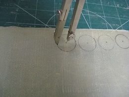
Slop intervened as tolerances are not consistent. Concluded the aft fuselage half ("C"-section) was too narrow and didn't have quite enough clearance to allow interference-free nesting of the forward section; it all folds up but not without some drag. Some scrap Monokote measures at .002"; that's at least .008" clearance more needed.
How do you stretch width without deconstructing and re-sheeting or worse yet - remaking the part? Decided to cut the part in half and add material to the center. Clamped some narrow stock to the work surface and hung the tail off the edge of the workbench. Hoping to restore cross-grain integrity by inlaying balsa 1/8" x 1/16" pieces in the five places seen.
Plan to add a longitudinal .025" balsa strip to center to widen the aft fuselage "C"-section to where it should be then add the cross-grain pieces.
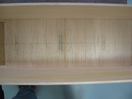
02-24-2019, 04:42 PM
#39
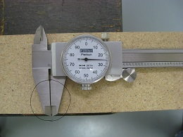
Actually, the fwd fuse bowed out around F-2 (where the sides bend to meet the firewall) measuring at 2.760" and the inside of the aft fuse section measures at 2.754"; interference of .006" (that's w/o covering) causing enough drag to be disconcerting... After all, .025" is almost not worth adding. Ended up adding a total of 1/16" to the center length of the aft fuse section. Bonded the five short pieces into one half and then joined the two halves to complete the "adjustment". Content now with the strength and clearance.
Found some scrap fiberglass sheet (.025" T) and began fabricating lots of glass "washers" to use for bearing surfaces, spacers, and retention means for the main hinge knuckle, and wing panels.

Taped magnets to fwd and aft fuse cross sheeting and tested the conversion to recovery phase in this short vid here:
Found some scrap fiberglass sheet (.025" T) and began fabricating lots of glass "washers" to use for bearing surfaces, spacers, and retention means for the main hinge knuckle, and wing panels.
Taped magnets to fwd and aft fuse cross sheeting and tested the conversion to recovery phase in this short vid here:
Last edited by H5606; 02-24-2019 at 05:05 PM.
03-10-2019, 02:09 PM
#40
Coated interior of fuel tank compartment with 30 min epoxy.
Located and opened up areas for the fold situation magnets in fwd and aft fuse sections.
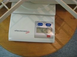
Gathered up majority of components for a/c including 6 servos (4 flight control servos, 1 throttle servo, 1 release servo) battery pack, engine, tank, and checked weight and CG. Excluding Rx and switch harness, extensions, wing sheeting, fuse top sheeting, hardware, covering, and any number of weight additions not thought of here.
Right at 16 oz. at this point with a slight nose-heavy attitude based on foamy chuck glider's CG (LE of "X" intersection). Reference to existing design weights of 20~28 oz. keeps me optimistic that this design still within reason. Present thinking that I need to keep everything as light as possible in the nose now. Projecting 256 sq in wing area.
Located and opened up areas for the fold situation magnets in fwd and aft fuse sections.
Gathered up majority of components for a/c including 6 servos (4 flight control servos, 1 throttle servo, 1 release servo) battery pack, engine, tank, and checked weight and CG. Excluding Rx and switch harness, extensions, wing sheeting, fuse top sheeting, hardware, covering, and any number of weight additions not thought of here.
Right at 16 oz. at this point with a slight nose-heavy attitude based on foamy chuck glider's CG (LE of "X" intersection). Reference to existing design weights of 20~28 oz. keeps me optimistic that this design still within reason. Present thinking that I need to keep everything as light as possible in the nose now. Projecting 256 sq in wing area.
03-12-2019, 07:58 AM
#42
Concern over changing incidence at high speed on the swept-forward surfaces has me also considering mixing aileron to elevator on the rear ones instead. Then, the front ones would only change incidence for the autorotation part. Hopefully a computer radio can be programmed to do all these mixes and condition changes...
03-21-2019, 08:25 AM
#45

Glad to see you getting back to this. I'm watching with interest.
 03-18-2020, 04:22 PM
#46
Long pause and sorting through items to address are: adding a carry-through tube for the two short wing pivot tubes at the intersection with the long one; spreading out the load for the spar box attach points; keying in drive horns for the flying surfaces; trimming pivot tubes to final length and retention means for the wing panels; sheer web installation, LE/TE install, and sheeting of flying surfaces; servo mounting and installation in the spar box/center section; trimming hinge tube to length and retention means for the fuse hinge knuckle; try stiffening up the aft fuse "C" section with the ramp and tri-stock mentioned at post #31; oh... and should do that once-in-a-lifetime shoveling out of clutter around the house.
Last edited by H5606; 03-19-2020 at 10:42 AM. Reason: very important addition
03-19-2020, 02:53 PM
#47
Evaluating flimsy balsa aft fuse for reinforcement: Placed balsa scrap between vertical surfaces at rear end on foamy glider and did some backyard testing - ramp on bottom doesn't appear to have any influence, so it must be in dead air since it's behind the hinge knuckle; just to confirm, moving ramp to top side resulted in pitch-up as expected.
03-19-2020, 03:49 PM
#48
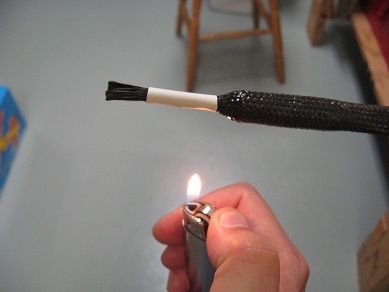
Carry through reinforcement for the spar tube intersections: Using a surface gauge to mark the midpoint of some left over bearing tube - being close is close enough to work with, turning the part over and re-marking helps you find exact center - it's between the two marks. Began opening up a through hole big enough to accommodate the carbon spar tube by hand to keep it centered. Worked hole open slowly with combination of drills and round files. Applied carbon sleeve braid on over the glass tube for strength, taped down one end, pulled tight, and cinched down other end with heat shrink tubing.

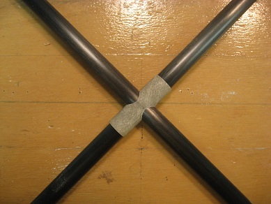
Last edited by H5606; 03-19-2020 at 04:09 PM.
The following users liked this post:
mgnostic (03-26-2020)
03-21-2020, 10:35 AM
#49
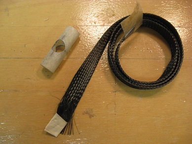
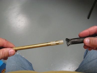
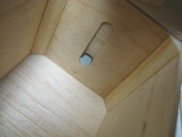
Pulled the carbon braided glass tube off a waxed brass tube handle, trimmed the ends off, and opened up the holes in the center; checked fit with carbon spar tubes. Laid out and drilled #33 clearance holes and cut out two 1/32" ply disks, marked and cut out notches (look like "Pacmans") to clear corners of center section reinforcement block; feathered edges and bonded into center section (control distribution box) as reinforcement for screw attachment holes.
-Just for my own reference: edited pictures down to 10% before posting; last two posts (#47, #48) were at 15% -

-Just for my own reference: edited pictures down to 10% before posting; last two posts (#47, #48) were at 15% -
Last edited by H5606; 03-21-2020 at 10:47 AM.
The following users liked this post:
mgnostic (03-26-2020)
03-25-2020, 07:38 AM
#50
Cut 1/32" balsa sheet into pieces for sheer webbing and bonded across spars with white glue. Sharpened aluminum tubing I had handy (better with brass) and located endpoints of wiring carry-through for a displaced slot on hinge knuckle. Removed hinge knuckle from fwd fuse and completed holes, joined holes with razor saw - this slot will hopefully allow pass through of wiring from receiver in fwd fuse to servos in hinge knuckle without pinching wires during fold-up. Last two pics show slot function from airplane mode to autorotation mode.


The following users liked this post:
mgnostic (03-26-2020)