e) Mounting Electronic Speed Controller (ESC) with the S.BUS2 current sensor.
ESC:
I'm familiar already with the Jeti-Hacker Master Mezon ESC with BEC that was selected for my Galactika.
I have one in my MythoS Pro already and know how it is mounted in a good way and the settings I use same in Galactika is same as I use in Master Mezon my in MythoS Pro. It was 10 min work to dail in all values in the new Master Mezon in Galactika. Jeti Box is used in my case to configure the ESC.
I use (latest) firmware 1.27 in my Master Mezon ESC.
Master Mezon 90 with BEC was selected for my Galactika despite this ESC is on the heavy side with 140 grams.
One slight irritating feature is that it has an external On-Off switch also, that I selected to mount
on left side of fuselage 40 mm (1.57 in) below middle of canopy. Extending the wires to the On-Off switch was needed.
Master Mezon 90 BEC specification:
Continuous Current: 90A
Voltage range: 5 - 51V
LiPo : 2-12 cells
BEC current : 10 Amp
BEC voltage : 5 - 8V
Dimensions : 36x20x109 mm
Weight : 140 grams
I had checked in another Galactik assembly thread over at Flying Giants
http://www.flyinggiants.com/forums/s...ad.php?t=87621
that Galactik had a tendency to be tail heavy, so I mounted the ESC as far forward in fuselage as possible to be ready for similar tendency in my Galactika.
I mounted the ESC on a plate on fuselage floor that was glued with some red beech pieces where the screws was holding the ESC through rubber grommets. The metal cooling plate on the ESC was exposed very well to air inlet in the nose. No obstacle for the air after it as flowed over the ESC except the current sensor that is placed just in front of the main air exit slot on underside of fuselage.
4 air inlet holes in nose and a rather large air outlet slot under the fuselage provide good cooling for ESC, motor, current sensor and LiPo flight battery.
I have my Master Mezon set to following important values.
Settings menu, Controller Settings:
Operation Mode: Normal
Acceleration 0-100% 0.50 s(sec)
Brake mode, Manual setting:
Brake begin pwr(power): 20%
Brake end pwr: 56%
Break dead time: 0.0 s
Brake speed: 0.3 s
Other ESC settings of importance:
Temp protection: 100 deg C
Max bat. current: 120 Amp
Max bat capac. (capacity): No limit (no motor cut off for max capacity usage)
Cutoff type: Slow down
Cutoff volt per cell: 3.1 volt
Off voltage set: 31.0 volt
SBEC voltage: 7.4 volt
Init. Point Type (throttle ch range): Fixed
Initial point: 1.10 ms (pulse width for trottle ch, measured previously with Jeti Box on throttle ch)
End Point: 2.03 ms (measured previously with Jeti Box on throttle ch)
Current sensor:
The current sensor I use is Futaba/Robbe item no 1678 (discontinued but still available in Germany).
It has proven to work excellent during two seasons in my MythoS Pro.
It has weight of 19 grams.
The sensor has to be upgraded with newer software then factory installed software, to get support for resetting mAh count to zero with a switch on the radio (otherwise reset has do be made with a button on the currecnt sensor). It is easy to upgrade the sensor via USB and a special upgrade program that Robbe made when they where in business.
To get support for the current sensor in Robbe/Futaba external Telemstry Box it has to have software version 1.003 (I had upgraded to that previously, via USB on PC with upgrade software).
The tricky part is to solder the plus cables on the metal solder points inside the current sensor.
You do not want a cold solder here.
But I knew from before when I did this work for the MythoS Pro how it was best done so it was no problem this time. The current sensor has also an external voltage connector and the plus and minus leads is soldered to plus and minus battery leads cables (on ESC side).
The sensor was mounted on a small 1,5 mm plywwod plate with some side support that alowed a gap for small welcro around the sensor case to secure it in place, there is also small welcro pieces under the sensor to help keep it is place.
Sensor is mounted just in front of the air outlet slot so it get very good cooling through it's cooling openings in sensor case.
The sensor record telemetry data for voltage, ampere and capacity (mAh).
The telemetry data from sensor is sent to Futaba R6308SBT receiver via S-BUS2 and receiver send it to the external Futaba/Robbe Telemetry Box that is mounted with a Futaba bayonet adapter in old 35 Mhz antenna hole on my Futaba 14MZ transmitter.
The current sensor is registered in the Telemetry Box by connecting the sensor directly to the Box with a servo lead and then register the sensor in he menu in the Telemetry Box.
This telemetry solution has worked without any problem at all for two seasons with my MythoS Pro.
It is fantastic that I could extend useful life of my Futaba 14MZ this way with telemetry, thanks to Robbe that developed this telemetry in cooperation with Futaba for Futaba FASST radios for the European market.
For me it mean I can use my 14MZ some more years and it will be about 10 years usage before I will retire it (I have used it for 8 years now).
The Telemetry Box has alarms for limits I set in it and can have vibration, speech and sound alarms.
I have a routine to always before a flight check LiPo flight battery voltage (that is around 41-42 volt if fully charged) and then check I have reset the mAh count to zero.
If the Scorpion Backup guard has kicked in I will get an alarm since I have 5.1 volt alarm threshold for receiver voltage (Backup Guard kicks in at 5 voltage and below).
I need no more telemetry then this really for my F3A flying. I feel I really can rely on this telemetry solution, proven by 2 seasons rather much F3A flying including competition flying, also in bad weahter.

Mounting plate for ESC on fuselage floor. Plate is a laminate of Carbon-Herex-Carbon material.


Jeti/Hacker Master Mezon 90 with BEC mounted as far forward as possible to avoid that the plane be tailheavy that it probably in most cases can be if not enough accessories can be mounted rather forward in fuselage. ESC has 4 rubber grommets that it is fastened to the mounting plate with.

ESC front view, excellent cooling capabilites from front air intake and then through the fuselage letting the air flow backwards over the current sensor that can be seen little blurry in the background.


The On-Off switch for the ESC. The lead had to be extended so the switch could be mounted where it is shown. Same switch from outside.
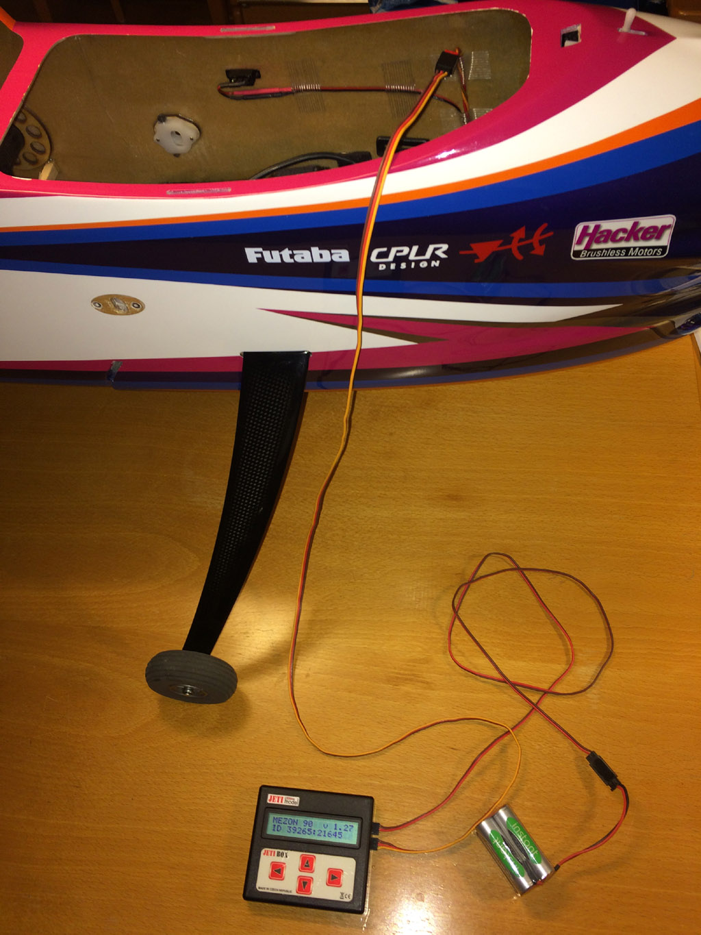
To program the ESC one connect a Jeti Box, with power from an external battery, with a servo lead to a cable from ESC. All changes made via Jeti Box is executed immediately (there is no "Save" button). If You have a Jeti radio You can also program the Jeti ESC from such Jeti transmitter that has Jeti Box emulator.

Futaba/Robbe 150 Amp current sensor 1678 (not made anymore) mounted in fuselage floor just in front of air outlet slot for best possible cooling of the current sensor. The current sensor has small cooling slots on side of the case. Current sensor cable connected to S.BUS hub.
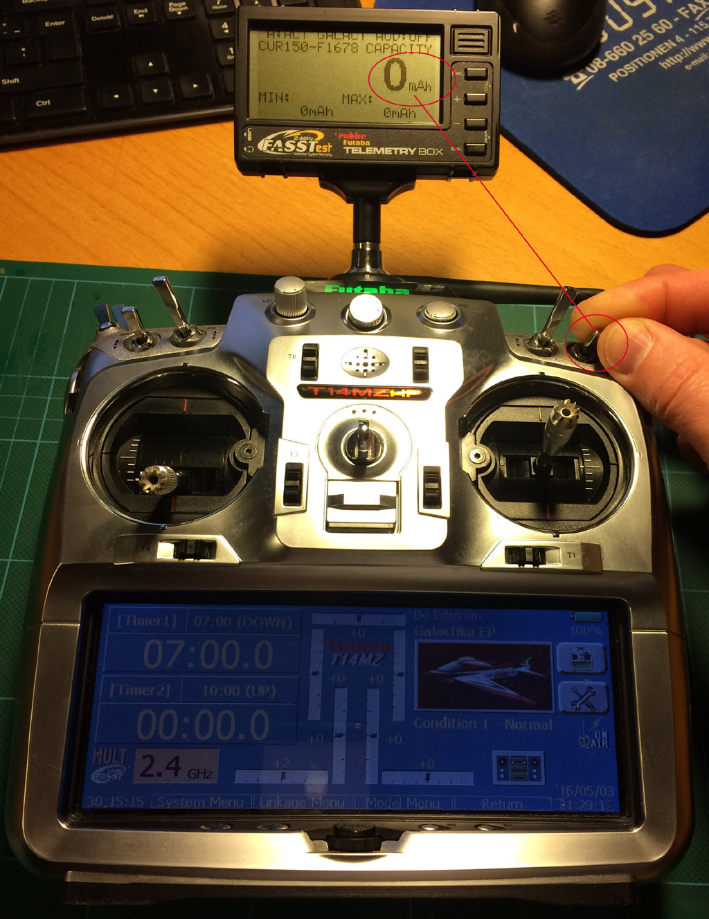
Futaba/Robbe external Telemetry Box F1666 (not made anymore) mounted on my Futaba 14MZ with a bayonet adapter in 35 MHz antenna hole. Capacity (mAh) is reset with switch SD (by flipping it On-Off two times quickly).

One nice side effect with using the Telemetry Box is that the 14MZ ist almost horizontal when hanging in the neckstrap. Without this extra weight (or a 35 MHz antenna mounted and extended) it is very bad center of gravity so TX tilt badly. All who has used a Futaba 14MZ know how annoying that is.
/Bo