


Hello?
 07-22-2019, 04:03 PM
#26


Like Dihedral makes ailerons less effective or that 72mhz is more reliable when the RX antenna is routed outside the balsa fuselage. Funny since we put all our 2.4 equipment on the inside unless its a CF structure.
Thinking about this a little more, since I have in the past built and painted a few Prather tunnel hulls and Deep Vee's for customers back in the day would that make me equally qualified as you to advise guys in the boat forums?
Thinking about this a little more, since I have in the past built and painted a few Prather tunnel hulls and Deep Vee's for customers back in the day would that make me equally qualified as you to advise guys in the boat forums?
BTW, since you seem to have forgotten, it used to be standard practice to route antennas out of the top of the fuse and up to the top of the vertical stab. It was also a standard practice to route the antenna inside the fuse using a zig zag pattern for better reception. My first two planes were routed in those ways per an instructor's directions in Idaho Falls ID. That was back in 1986 and, since AM and FM systems haven't really changed, that is unless you have a PCM or 2.4GHz system, that information is still good. A CF control rod can still affect how a signal is received, considering CF is used to make antennas used in two way communications but, then again, that's old school tech that's not used anymore for anything in R/C, especially aircraft.
Since you know everything, what fuel do I need for my boats? I have boats that run .21, .45 and .67 sized engines. Can I get away with 5% nitro or is that too much?
 07-22-2019, 04:21 PM
#27

I started running antennas inside in 1983. Having an antenna external on a sailplane was just ugly, I just continued doing it on my power airplanes as well. You are correct that external was pretty much standard though although there is no supporting data that it was any better.
Fuel for your boats. Without knowing your compression ratio, plug heat and load that is an unrealistic question. That being said, I do not Veiw myself as equally qualified in the boat world. You clearly have much more experience and I am one who places value on experience. There is not much you could tell me about R/C boats that I would not take at face value. When it comes to the details of high performance power boats I can easily admit that " I don't know what I don't know ". It's a shame that you seem to not value experience in the same manner but I suppose it's humanity's differences that keeps life interesting.
Fuel for your boats. Without knowing your compression ratio, plug heat and load that is an unrealistic question. That being said, I do not Veiw myself as equally qualified in the boat world. You clearly have much more experience and I am one who places value on experience. There is not much you could tell me about R/C boats that I would not take at face value. When it comes to the details of high performance power boats I can easily admit that " I don't know what I don't know ". It's a shame that you seem to not value experience in the same manner but I suppose it's humanity's differences that keeps life interesting.
 07-23-2019, 03:58 AM
#34
Banned
Like Dihedral makes ailerons less effective or that 72mhz is more reliable when the RX antenna is routed outside the balsa fuselage. Funny since we put all our 2.4 equipment on the inside unless its a CF structure.
Thinking about this a little more, since I have in the past built and painted a few Prather tunnel hulls and Deep Vee's for customers back in the day would that make me equally qualified as you to advise guys in the boat forums?
Thinking about this a little more, since I have in the past built and painted a few Prather tunnel hulls and Deep Vee's for customers back in the day would that make me equally qualified as you to advise guys in the boat forums?
The 2.4 has little choice based on the current designs. But try 2.4 in a submarine sometime for a real lesson in radio systems. And a 2.4 low in the hull of a boat can be blocked by waves. Makes for loads of fun.
07-23-2019, 04:03 AM
#35
Banned
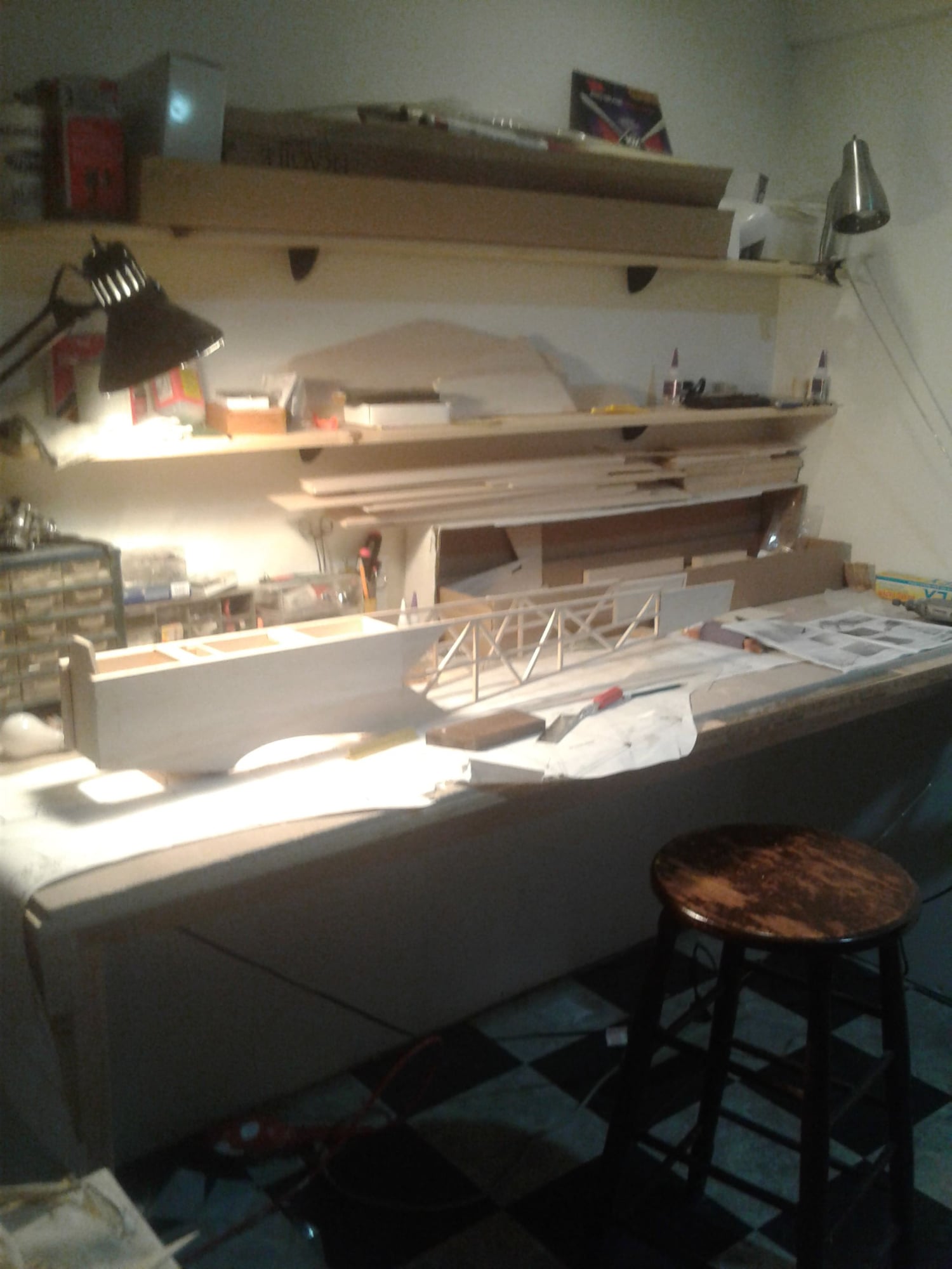
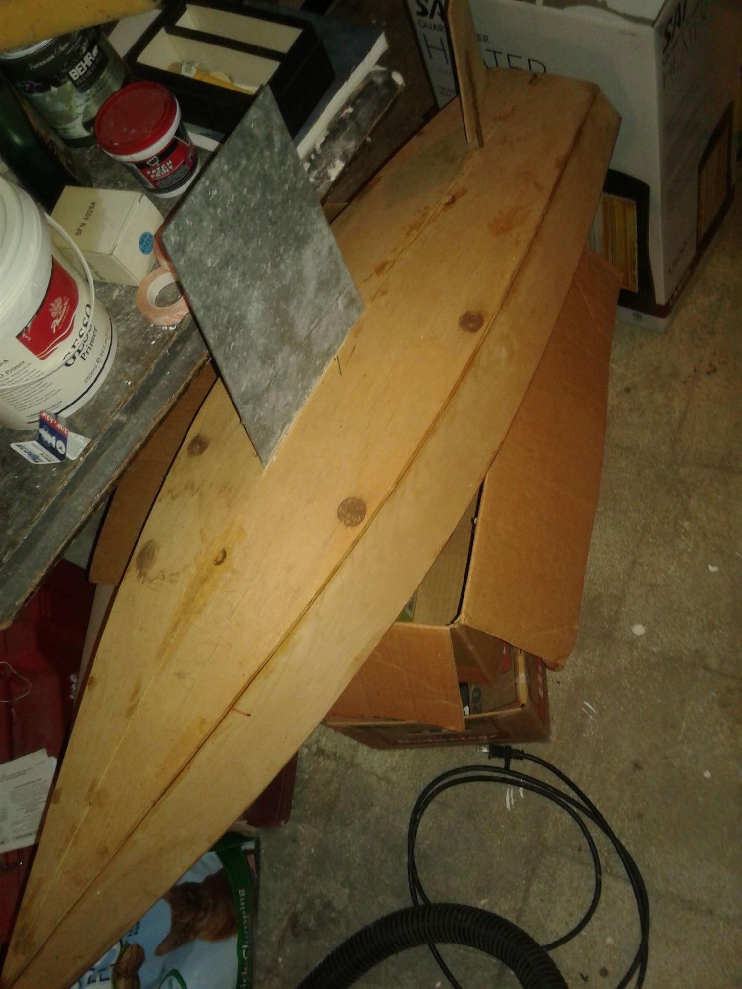
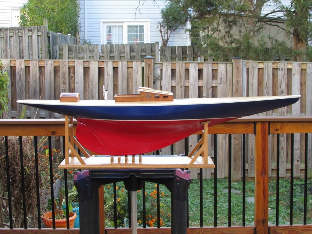
My Six Meter during construction. Glass hull, the rest scratch built by me. White Oak planked deck with Mahogany trim. 60 inch LOA and about 22 pounds rigged.
 07-23-2019, 07:29 AM
#36
Banned
Why not? You seem to know everything about everything else.
BTW, since you seem to have forgotten, it used to be standard practice to route antennas out of the top of the fuse and up to the top of the vertical stab. It was also a standard practice to route the antenna inside the fuse using a zig zag pattern for better reception. My first two planes were routed in those ways per an instructor's directions in Idaho Falls ID. That was back in 1986 and, since AM and FM systems haven't really changed, that is unless you have a PCM or 2.4GHz system, that information is still good. A CF control rod can still affect how a signal is received, considering CF is used to make antennas used in two way communications but, then again, that's old school tech that's not used anymore for anything in R/C, especially aircraft.
Since you know everything, what fuel do I need for my boats? I have boats that run .21, .45 and .67 sized engines. Can I get away with 5% nitro or is that too much?
A great many things effect signal propagation. Power out of the TX combined with Rx sensitivity just to start. Neg 80 db is a typical level for our receivers. Very difficult to see on a scope because background radiation runs at those levels too. Frequency is another big factor. 75MHz for the sub guys can go as deep as 10 feet depending on water condition. And sometimes even more. While 2.4 simply does not penetrate water to any real amount. An inch if you're lucky. Weather also impacts propagation. Humidity will play havoc. In the micro wave communications world it's called Rain Fade. 23 Gig MW systems I could push a signal 10 miles in the desert at 100 mW. Let it start to rain and I'd be lucky to go 100 yards. But my Satcom systems at 7 Gig would do 23,000 miles on just a couple of Watts. And even the sun can play with it. Ever get a hit when you fly past the sun? It happens. Not often but it does happen. And I suspect it happens more often with 2.4.
But don't believe me. I've just worked the environment for over 40 years.
07-23-2019, 01:41 PM
#37
Anything, ANYTHING to include the air will attenuate the signal of any radio. Placing the 72 antenna outside the fuselage gets it away from ANY potential interference. Do you have to? NO! But I have also seen it solve problems.
The 2.4 has little choice based on the current designs. But try 2.4 in a submarine sometime for a real lesson in radio systems. And a 2.4 low in the hull of a boat can be blocked by waves. Makes for loads of fun.
The 2.4 has little choice based on the current designs. But try 2.4 in a submarine sometime for a real lesson in radio systems. And a 2.4 low in the hull of a boat can be blocked by waves. Makes for loads of fun.
07-23-2019, 01:51 PM
#38
I agree that separating the antenna from metal pushrods, cables, servo leads can improve signal reception. That however is not what we were discussing. The claim was that the fuselage shell ( most cases balsa ) could impede or attenuate signal. You can theorize all you want but unless you have supporting data it is nothing more then theory especially at 72mhz. In fact as frequency increases it would be more of a consideration. So why was it such a concern with 72mhz but not with 2.4gz at a lower power level? Theory is nothing more unless it is put into practice. Although I agree that you have more education outside of the hobby as eveidenced by the extensive resume you for some reason felt the need to PM to me, I have much more experience and at a much higher level in the hobby then you. Please keep that in mind.
07-23-2019, 02:09 PM
#39
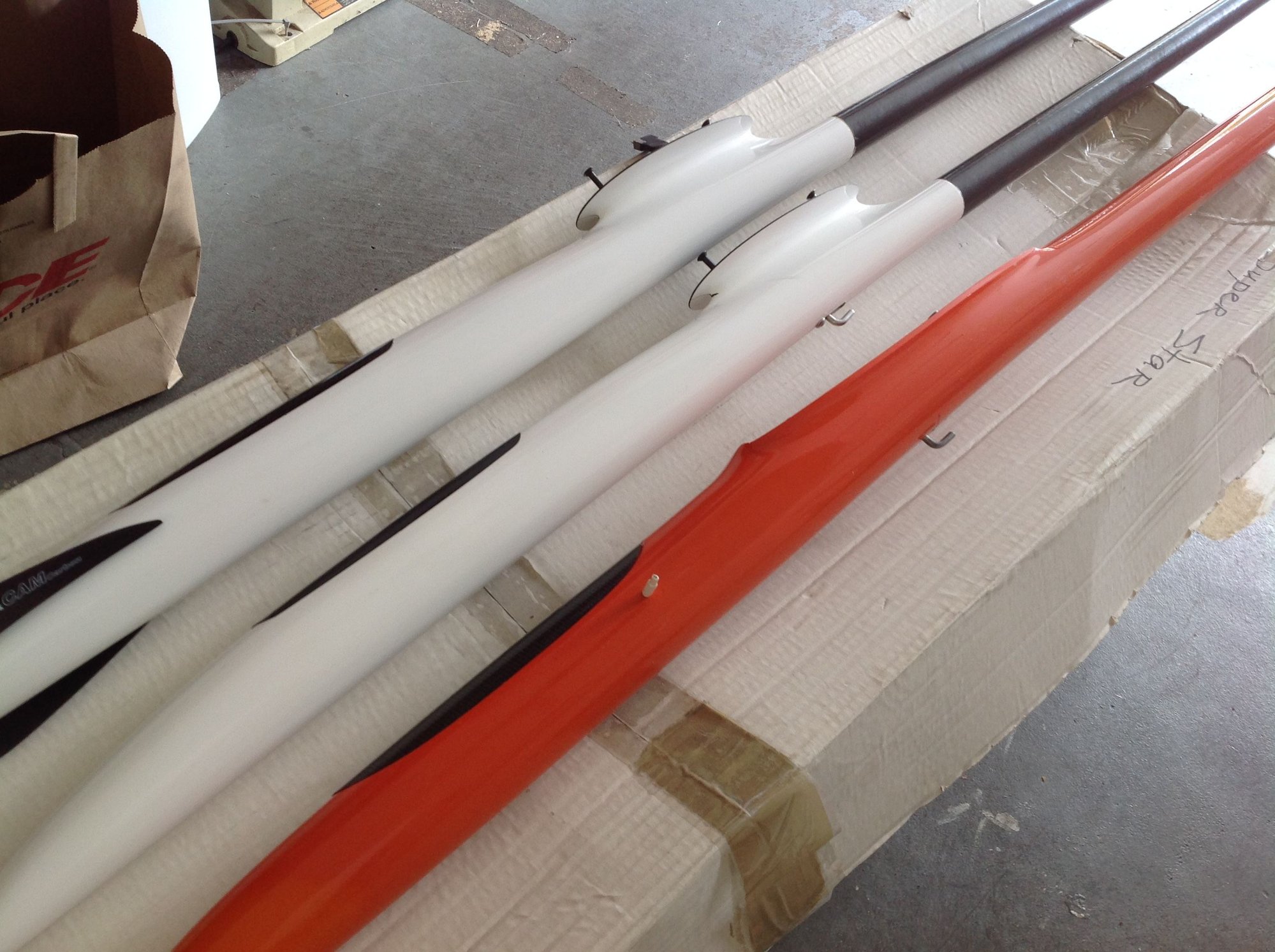
Note the short stub antenna on the Orange fuselage
Absolutely correct, as I said in my previous post it should be more of a concern with 2.4ghz due to the fact that the higher frequency does not " penetrate " as well as lower frequencies. Yet in spite of that the standard install is to have 2.4ghz antennas internal. A good example is this lineup of my contest sailplanes. Note that the two white sailplanes have Kevlar construction and the antennas are internal. The Orange sailplane is CF construction and has its antenna ( just the last 1/2" ) external. All 3 sailplanes have topped 1,500 ft in multiple locations. Like I said to Appowner. Keep in mind that when it comes to the hobby I have more experience and at more then just an armature level!
Last edited by speedracerntrixie; 07-23-2019 at 04:22 PM.
07-24-2019, 03:12 AM
#40
Banned
A 1/4 wave antenna for 2.4 is just shy of 5 inches long. All of which should ideally be outside any carbon. Unless there's something else at work here. Please enlighten us with your expertise and explain WHY you have only 1/2 inch of antenna outside the fuse?
07-24-2019, 04:34 AM
#41
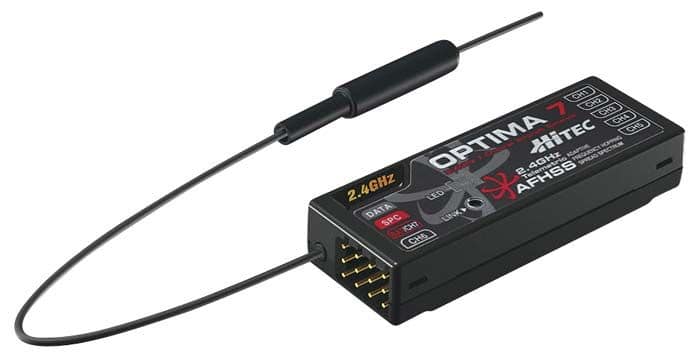
That one has the Hitec Optima 7 channel RX. Hitec Optima receivers have a boosted Omni Directional antenna. Only the last 1/2" is active. Installed as per manufacturers instructions. I have been flying the Hitec A9 TX ( I have 3 of them ) with the Optima 7 and 9 channel receivers since 2010. They have been in glow powered models, gas powered with CDI being run off RX power, Electric power and sailplanes. Almost all of those aircraft incorporated composite construction. Mostly fiberglass with CF re enforcement where needed. I have lost only one model due to signal loss. User induced. I placed the antennas ( Optima 9 channel w/dual antennas ) next to the fuel tank. It was either that or next to the digital elevator servos. I didn't really like either option but went with the one I thought best. That airplane did fly successfully for close to two years prior to the loss. As we both know, noise floor fluxuates.
07-24-2019, 04:49 AM
#42
I'm more curious as to shy he has such a sharp bend in the antenna tube? I'd be worried that the shield braid would be damaged by the sharp bend, changing the effective length of the antenna from .5" to the overall length between the tube curve and the end of the antenna
07-24-2019, 04:54 AM
#43
There is no bend. The " Boda " part of the antenna is mounted on the servo tray 90 degrees to the fuselage length. That sailplane has hundreds of flights on it and multiple wins.
Thinking about this, reminds me of a cute little story that relates to the question. When I worked for LM, I was tasked to build some timed cables. These were to be coax cables 20' long with N connectors. The hard part was they were to be timed with a tolerance of +- 5 picoseconds. So I went and built the cables and sent then over to the test tech. He returned a day later with half the cables with dimensions he wanted removed to tune them to the electrical length to make them match the other half. The amounts he wanted removed were between 1/8" and 1/4" which is huge with relation to the spec. After finding out his test method and discovering that he was using an Anritsu network analizer that I had actually built and tested while I was working for Anritsu. I shared some knowledge that helped us revise the testing process. I performed a new 12 term calibration on the analizer and then told him to allow 1 hour of run time on the analizer to let the frequency source module come up to temp and stabilize. The other key, the one that applies here was to arrange the cables all into 4' loops as the bend radius was having a slight affect. The end result was that all 40 cables passed test spec without requiring any rework.
Thinking about this, reminds me of a cute little story that relates to the question. When I worked for LM, I was tasked to build some timed cables. These were to be coax cables 20' long with N connectors. The hard part was they were to be timed with a tolerance of +- 5 picoseconds. So I went and built the cables and sent then over to the test tech. He returned a day later with half the cables with dimensions he wanted removed to tune them to the electrical length to make them match the other half. The amounts he wanted removed were between 1/8" and 1/4" which is huge with relation to the spec. After finding out his test method and discovering that he was using an Anritsu network analizer that I had actually built and tested while I was working for Anritsu. I shared some knowledge that helped us revise the testing process. I performed a new 12 term calibration on the analizer and then told him to allow 1 hour of run time on the analizer to let the frequency source module come up to temp and stabilize. The other key, the one that applies here was to arrange the cables all into 4' loops as the bend radius was having a slight affect. The end result was that all 40 cables passed test spec without requiring any rework.
Last edited by speedracerntrixie; 07-24-2019 at 05:21 AM.
07-24-2019, 05:43 AM
#44
Banned
That one has the Hitec Optima 7 channel RX. Hitec Optima receivers have a boosted Omni Directional antenna. Only the last 1/2" is active. Installed as per manufacturers instructions. I have been flying the Hitec A9 TX ( I have 3 of them ) with the Optima 7 and 9 channel receivers since 2010. They have been in glow powered models, gas powered with CDI being run off RX power, Electric power and sailplanes. Almost all of those aircraft incorporated composite construction. Mostly fiberglass with CF re enforcement where needed. I have lost only one model due to signal loss. User induced. I placed the antennas ( Optima 9 channel w/dual antennas ) next to the fuel tank. It was either that or next to the digital elevator servos. I didn't really like either option but went with the one I thought best. That airplane did fly successfully for close to two years prior to the loss. As we both know, noise floor fluxuates.
07-24-2019, 05:58 AM
#45
Banned
Note: Numbers may vary depending on specific make/model of ILS. But the numbers used are from my personal experience. Sad that such a disclaimer is necessary to prevent trolling.
Instrument landing system Localizer has 14 sets of antennas. Each set has two active and several passive antennas. A total of 28 cables, roughly 120 feet each, run along the 120 foot or so of the array feeding the active antennas. These cables must be cut to specific electrical lengths. A Vector Volt Meter was the tool when I was doing it. It measured the length in degrees of phase. The kicker? The cables were not all the same. Four more cables to the equipment van also had to be phased. All in all we would start with some 4,000 foot of cable which had to be one continuous length to ensure it all reacted the same to the environment. No splices! No pieces! All one cable almost a mile long. And a crap load of N connectors because 1. the cables had to be measured with a connector on each end and 2. when you pulled a connector to trim the cable, you had to put a new connector on. No reuse of connectors.
My Workcenter took 18 days to restore an antenna array which had been center punched by a T-38 aborting a take-off. The Electronic Installation group across town estimated 1 to 2 months to restore it. Being a flight training base, flight ops had to be suspended until the ILS was repaired. We had the manpower, the knowledge and the equipment necessary to do it. 18 days vs 1-2 months saved the Air Force millions in lost training. In the meantime two of my E-3 Airmen took on the task of handling all the daily maintenance, checks and monitoring of three other full ILS systems, a TACAN and a TVOR.
Just one example!
07-24-2019, 05:59 AM
#46
Banned
I'm more curious as to shy he has such a sharp bend in the antenna tube? I'd be worried that the shield braid would be damaged by the sharp bend, changing the effective length of the antenna from .5" to the overall length between the tube curve and the end of the antenna
07-24-2019, 06:35 AM
#48
Banned
.................................................. ............. After finding out his test method and discovering that he was using an Anritsu network analizer that I had actually built and tested while I was working for Anritsu........................................... ...
Anritsu
