


Unequal elevator halves
 01-30-2014, 09:41 AM
#1
Senior Member
Thread Starter
Join Date: Sep 2008
Location: Mumbai, INDIA
Posts: 2,224
Likes: 0
Received 0 Likes
on
0 Posts
Hi,
while I was setting up the throws on my GP Reactor 46 today I found that, with the LE of the two elevator halves inline with the stab's LE, the TE of the two was not level. When looking from behind, one TE is definitely lower than the other. This is not an alignment problem because they halves are otherwise fine. Looks like the two halves are non symmetrical. I had noticed a similar problem with the elevator halves on my Reactor Bipe earlier. I summarize that GP has a elevator half line that is supposed to make one type of half that is to be used for both left & right sides. But they are making the halves nonsymmetrical about the chord line.So when the flip it over, the TE of the two halves don't end up level. Anyone else have the same observation and how to correct this?
Ameyam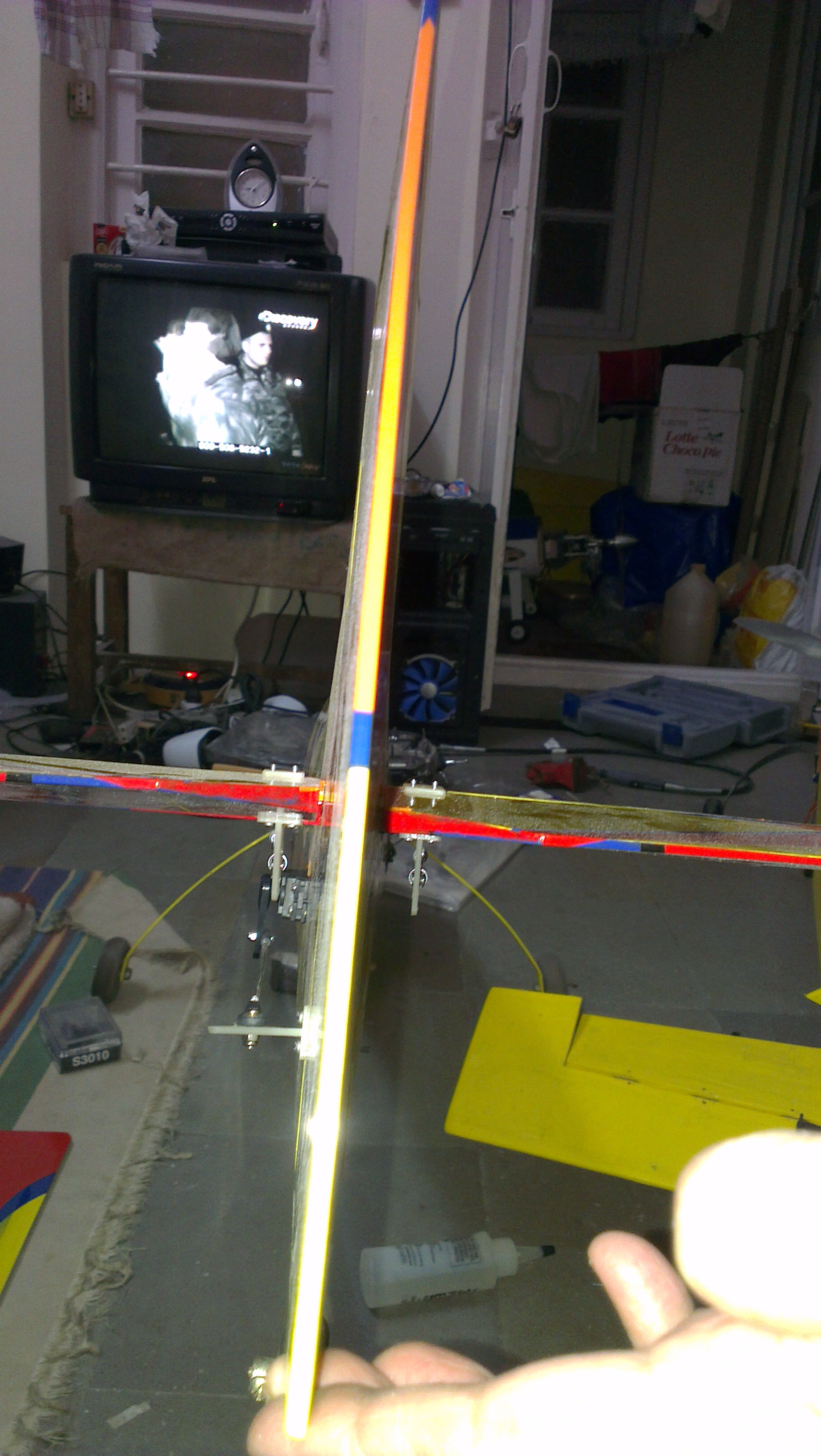
 01-30-2014, 10:37 AM
#2


Join Date: Nov 2005
Location: Poolesville, MD
Posts: 12,624
Likes: 0
Received 0 Likes
on
0 Posts
Yup, your geometry is not identical for both halves.
You need to make sure that your horn positions are the same, and that your linkages have identical lengths.
This includes the arms you have installed on the elevators with the eyelets. Minor differences cause somewhat large changes.
You also need to check the position of both elevators at their extreme travels as well.
Hopefully you put an identical minimum gap in the hinge so the elevators are free to move to the same extreme position.
If so adjust your linkages so that the two elevators line up at full up and full down.
Be careful with warping. Any minor warping of the surface may cause you to misadjust the mid and end points.
Try to AVOID using radio trims and mixing to try to fix this, the results are always sub optimal.
Instead do everything mechanically.... but first start with the servo arms get exactly the same angles and lengths.
01-30-2014, 11:32 AM
#3
Senior Member
Thread Starter
Join Date: Sep 2008
Location: Mumbai, INDIA
Posts: 2,224
Likes: 0
Received 0 Likes
on
0 Posts
Hi Opjose,
all the point check out- everything thing is same except one- the linkage lengths are not identical because the model is mot wide enough for two servos back to back. In my case one servo is infront t of the other. However that doesn't matter here- I took the snap without the battery. The elevators are located with the LE inline with the stab.
To me it looks like a manufacturing issue but I don't have time to correct it coz the event I am readying the model for is next weekend.Is there some way to minimise the problem? My bipe flew beautifully inspite of it
Ameyam
01-30-2014, 12:25 PM
#4

There are various ways to do the line up but I use a couple of carbon fiber rods taped to the top surface of the elevator and pointing aft so they meet about 12 inches or so behind the rudder. That way you can match the neutrals and end points and if your radio is capable, you can match the deflections through out the travel range.

 01-30-2014, 12:54 PM
#6
Join Date: Nov 2005
Location: Poolesville, MD
Posts: 12,624
Likes: 0
Received 0 Likes
on
0 Posts
Hi Opjose,
all the point check out- everything thing is same except one- the linkage lengths are not identical because the model is mot wide enough for two servos back to back. In my case one servo is infront t of the other. However that doesn't matter here- I took the snap without the battery. The elevators are located with the LE inline with the stab.
To me it looks like a manufacturing issue but I don't have time to correct it coz the event I am readying the model for is next weekend.Is there some way to minimise the problem? My bipe flew beautifully inspite of it
Do you mean that the two servos driving the elevators are NOT "side by side".
Normally servos are never placed one in front of the other when servicing two elevator halves.
Servos that sit just in front of the leading edge of the elevator are "side by side" for all intents and purposes and if you've set things up SHOULD have identical linkage lengths.
If not you did not reverse one of the servos via your TX, a reversed servo, or a servo reverse as you should have.
This is NOT a "manufacturing issue" it is a "user error".
Zeeb is refering to differences in the counterweights, etc... which in part can be due to warping, or placing one elevator higher than the other when hinging. That does not seem to be the case here.
In your case the trailing edge of the elevators ( assuming that the elevators are properly hinged and NOT warped ) must be identical at different stick postions. You have to fix the geometry to make this so.
If you do not, you may not notice the problem until you perform a tight loop or other manouver. The difference will cause the plane to favor one side over the other.
01-30-2014, 01:03 PM
#7
Join Date: Nov 2005
Location: Poolesville, MD
Posts: 12,624
Likes: 0
Received 0 Likes
on
0 Posts
The elevators are not warped from the LE to the TE.
Rather the 4-40 screw "horns" he is using are at different positions relative to each other.
The right one is slightly forward of the left. --- Geometry is wrong.
01-30-2014, 01:05 PM
#8
Jose, what he is saying is that the rear of the fuse is fairly narrow so there is not enough room to mount the servos in the same place on both sides of the fuse. One servo has been moved forward of the other. This was very common when we started putting servos back in the tail of our pattern airplanes and will not lead to an issue of UN-equal travel, the geometry is the same it's just that one servo is farther away from the hinge line then the other.
Check the elevators for warpage, i'm sure you will find it.
Check the elevators for warpage, i'm sure you will find it.
01-30-2014, 01:11 PM
#9
Those look like nylon control horns to me. Yes they do appear to be in different locations but that is because the elevator halves are not trimmed to match at the root. He has them matching at the tip where the counterbalance matches up with the stab LE. The elevators have a twist to them. He should match the halves at the root then twist the elevator by hand and re-shrink the covering and keep repeating that process until everything matches.
01-30-2014, 01:13 PM
#10
Join Date: Nov 2005
Location: Poolesville, MD
Posts: 12,624
Likes: 0
Received 0 Likes
on
0 Posts
If you've followed Ameyam's other posts, issues and errors though, I'll bet this is a geometry problem.
In the photo one surface merely appears to be higher than the other and the angle of the 4-40 horns he is using does not appear to be equal.
It could be that is an illusion, but I'll put my money on a "user error".
01-30-2014, 01:25 PM
#11
Join Date: Nov 2005
Location: Poolesville, MD
Posts: 12,624
Likes: 0
Received 0 Likes
on
0 Posts
Yup you're right.
You can get the full screen image and you can clearly see that they are nylon horns.
Yes they do appear to be in different locations but that is because the elevator halves are not trimmed to match at the root. He has them matching at the tip where the counterbalance matches up with the stab LE.
The elevators have a twist to them. He should match the halves at the root then twist the elevator by hand and re-shrink the covering and keep repeating that process until everything matches.
Yup, I see it now too. The larger image makes it plain. There is indeed a LOT of warp to the elevator itself, and he did NOT attempt to match the trailing edges at the root first as he should have.
You can get the full screen image and you can clearly see that they are nylon horns.
Yes they do appear to be in different locations but that is because the elevator halves are not trimmed to match at the root. He has them matching at the tip where the counterbalance matches up with the stab LE.
The elevators have a twist to them. He should match the halves at the root then twist the elevator by hand and re-shrink the covering and keep repeating that process until everything matches.
01-30-2014, 01:27 PM
#12
Pretty sure it is an illusion. I don't get where you see 4-40 horns? I see nylon horns with 4-40 push rods, clevis. Rudder is a ball link on a nylon horn ( Big No No ). I agree that he does not have the experience needed to set up this type of airplane perfectly and there may very well be some geometry discrepancies but I still think most of the issue here is a twist in an elevator.
 01-30-2014, 02:18 PM
#15


Join Date: Feb 2005
Location: Georgetown, KY
Posts: 819
Likes: 0
Received 0 Likes
on
0 Posts
01-30-2014, 03:19 PM
#17
Senior Member
Join Date: Jan 2002
Location: OR
Posts: 680
Likes: 0
Received 0 Likes
on
0 Posts
I had one of the early GP ARF's, A G202 powered by a Webra 1.20 that was like this. After several attempts to straighten the elevators I finally gave up and let them be different. At neutral one slightly up and the other slightly down. For my type of general sport flying it didn't seem to make much difference (not a whole lot of 3Ding)...........RJ
01-30-2014, 05:57 PM
#18
Senior Member
Thread Starter
Join Date: Sep 2008
Location: Mumbai, INDIA
Posts: 2,224
Likes: 0
Received 0 Likes
on
0 Posts
Guys, just hold on.
Opjose, curt as it may seem, people learn over time. I wish you would pick that up
Those at plain & simple white nylon horns. I initially had ball links in with 2-56 threaded push rods but they felt a bit delicate & likely to snap. Plus my airplane needed tail weight. So I changed over to 4-40 pushrods with Dubro spring steel clevices bothsides. Everything else is setup exactly same
What I did do was adjusted the neutral to live up the LE of the stab & elevator. That's the counterbalance area you are referring. I did tryto balance the roots with the TX but that meant the counterbalances were out & I felt this will add a roll to the tail. I wanted to confirm through this thread that the same was acceptable
Basically the halves are warped. This as an ARF with airfoiled elevator, not just one with rounded tips. So not sure how much the warp will come out with tightening coveringg Will give it a try though
There is not much I can do with the servo position. That's how the model was designed. At the most I can try & match the deflections through TX, that's what I normally do
Ameyam
01-30-2014, 08:43 PM
#21
Join Date: Dec 2005
Location: Victoria,
MN
Posts: 3,934
Likes: 0
Received 0 Likes
on
0 Posts
Hey bud....
I have had the same issues with my planes (great planes) I think I had some of the same issues with my RIP reactor bip .60 when I was trying to line up my elevators...
The factory places the elevators on so I can't change how they were glued in....
I don't think it was that far out of whack but yeah....mine was like that as well....
It really f's up a guy, when you are as particular as ME..... irritating to say the least..
I don't think it was warped....sounds like it wa built wrong...
01-31-2014, 12:26 AM
#22
Senior Member
Thread Starter
Join Date: Sep 2008
Location: Mumbai, INDIA
Posts: 2,224
Likes: 0
Received 0 Likes
on
0 Posts
Well, if I were to pust more pics on the setup, you would see I am pretty particular with the way I put it together. I am mostly done with Reactors for a bit of time but this was put together for the demo and once that is done, it will be my sunday flying airplane. So I took particular care and used some of my best hardware. Still ending up with this problem is a real bummer.
Moving forward. I am getting my heatgun to try and take some warp out of the elevator. Asking one side to do all the de-warping is meaningless so I am going to do a bit on both sides. Will try and get the TEs atleast in line. Lets see how it comes out
Ameyam
Moving forward. I am getting my heatgun to try and take some warp out of the elevator. Asking one side to do all the de-warping is meaningless so I am going to do a bit on both sides. Will try and get the TEs atleast in line. Lets see how it comes out
Ameyam
01-31-2014, 12:38 AM
#23
Looking at the picture, could it be that the elevators are handed and they have been covered wrongly at the factory and you have two left hand or two right hand elevators although covered to look like a pair.
Just a thought.
Just a thought.