


Pulse 125 Pilot Size
 10-20-2013, 06:34 AM
#1

Thread Starter

I am beginning the assembly of my Pulse 125 (Yep, just took it out of the box yesterday.) I am going to put a pilot in it, but before I order one I was wondering what would be an appropriate size? I have seen pictures on RCU, but am still not sure.
Last edited by hookedonrc; 11-18-2013 at 01:55 PM.
 10-20-2013, 07:01 AM
#3
Thread Starter
I bought it at a local hobby shop over a year ago when it was closing. It has been sitting on top of my garage fridge since then while I was working on other planes. Now I have all the stuff to put it together, DLE 20, servos, receiver, and a list of mods to do as I put it together. Yesterday I started by moving the LG forward to reduce the tendency to nose over. I will also doing dual elevator controls and other reinforcements. When it flies, it will be ready.


 10-20-2013, 03:17 PM
#5
Senior Member

HookedonRC, I put a 1/7 pilot in - HAN9111.
If it's of any use to you, my build photos - 623 of 'em - are at http://www.flickr.com/photos/rests/s...7627676443589/.
10-20-2013, 03:43 PM
#6
Thread Starter
Thanks grosbeak, I will certainly use them for reference. I have already moved the gear forward and will make most of the mods suggested in the long thread here on RCU. On the double elevator pushrods, I am going to use the Sullivan S559 which is a splitter for 4-40 rods. I am going to try to do the double elevator and the rudder using the 4-40's without removing the covering. However, if I have to, I will. I just finished recovering the fuse of an Ultra Stick Lite, so just redoing the bottom of the 125 should not be a big deal.
Thanks too, for the pilot size info.
Thanks too, for the pilot size info.
10-22-2013, 06:46 PM
#8
Thread Starter
Grosbeak
Now that I have had a chance to look the fuse over, it looks like removing the covering is the best option for putting in the second elevator control rod. It will also give me the chance to add a bulkhead if it is needed. I cut away the covering like you did and now am just waiting for the new 4-40 rods that are on the way.
Now that I have had a chance to look the fuse over, it looks like removing the covering is the best option for putting in the second elevator control rod. It will also give me the chance to add a bulkhead if it is needed. I cut away the covering like you did and now am just waiting for the new 4-40 rods that are on the way.
10-23-2013, 03:53 AM
#10
Thread Starter
Thanks Tailskid, I am also going to use the idea for the bellcrank to activate the choke mechanism. Will probably route it out the side near where I will install a fuel dot.
10-23-2013, 05:29 AM
#11
Senior Member
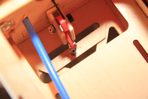
You've probably seen the pics but for the sake of posterity here's how I made my bell crank, and my choke connections.
The bell crank is easy to make with a leftover servo arm, some wood and fasteners.
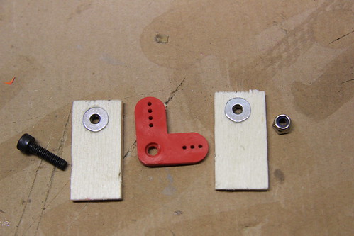
Put 'em together...
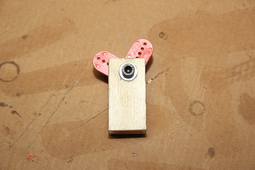
... and glue on a base plate.

I used a Du-Bro easy connector to connect wire to the choke arm.
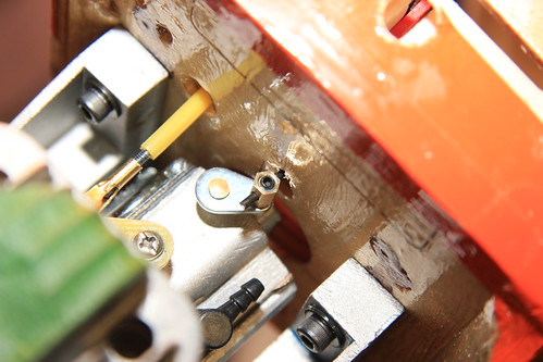
The wire connected with a Z-bend to the bell crank. I'm not generally in favour of L-Bends or Z-bends as push rod connections but it worked well here.
I added a clevis to the other end of the bell crank and a bit of internal structure to guide the push rod.
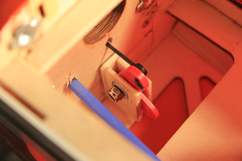
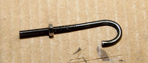
Some threaded rod for the choke handle.
Threaded rod bent to shape with a stopper nut.
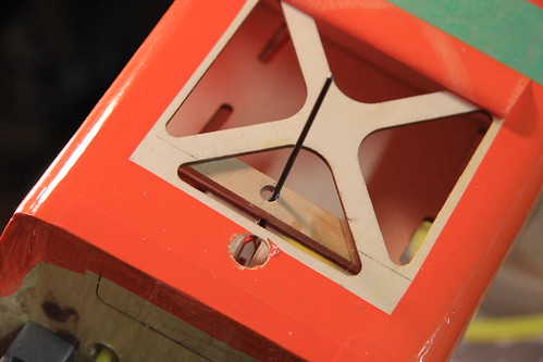
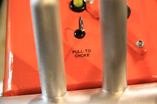
After recovering the bottom, I added a grommet and a decal to polish it off.
The bell crank is easy to make with a leftover servo arm, some wood and fasteners.
Put 'em together...
... and glue on a base plate.
I used a Du-Bro easy connector to connect wire to the choke arm.
The wire connected with a Z-bend to the bell crank. I'm not generally in favour of L-Bends or Z-bends as push rod connections but it worked well here.
I added a clevis to the other end of the bell crank and a bit of internal structure to guide the push rod.
Some threaded rod for the choke handle.
Threaded rod bent to shape with a stopper nut.
After recovering the bottom, I added a grommet and a decal to polish it off.
10-23-2013, 08:19 AM
#12
Thread Starter
Your plan for the choke mechanism is pretty much what I am going to do except for exiting out the side of the fuse. I have enough servo arms to build these for any plane I own if necessary. They are like rabbits and seem to add more each time I open the drawer I keep them in.
10-24-2013, 03:56 AM
#14
Thread Starter
I am hoping that the 4-40's with outside sheathing will be strong enough to avoid an outside brace. If I can keep them in a straight line from servo to control horn I think it can be done. I won't know until they get here and I start trial fitting them. And if I have to, I have built carbon pushrods for my ultra stick lite and can do so for the 125.
11-03-2013, 11:52 AM
#15
Thread Starter
Here are some pictures of my progress. A list of what has been done:
1. Moved the LG forward using the front holes on the fuse for the back holes on the gear. Had to cut away a little of the bay area ahead of the bulkhead to get to the area for the blind nuts, but that is done and when I am finished with all the other mods, I will fill in the old holes and recover the front.
2. I replaced all of the tailfeather control rods and now have 4-40's in place and additions to the bulkheads for strength.
3. Added the second elevator control horn and ran a control rod to a splitter on the elevator servo (Sullivan S559) for 4-40 rods. If you ever use this, I recommend tapping the spring loaded connector with a tap. I messed up one by just using the control rod and screwing it in.
4. I will be adding a Sullivan tail wheel bracket, but not needed yet. On the tail, I used some scrap balsa and covered it in white. It is bare wood where the regular tail wheel usually goes. Can't tell now.
5. I moved the elevator servo more to the center of the plane to allow for the second control rod and splitter to better align when the rods are in place.
6. I checked the control rod of the elevator, added more CA, and it seems to be very strong now.
7. Almost forgot... I epoxied the tail and elevator in place. The two bolts system just doesn't cut it on a plane of this size.
So Far, things are going well and I am really glad I removed the covering from the bottom of the fuse. It would have been a real pain to remove and reinstall the bigger control rod sleeves if I hadn't.
Last edited by hookedonrc; 11-03-2013 at 11:58 AM.
11-18-2013, 07:24 AM
#18
Thread Starter
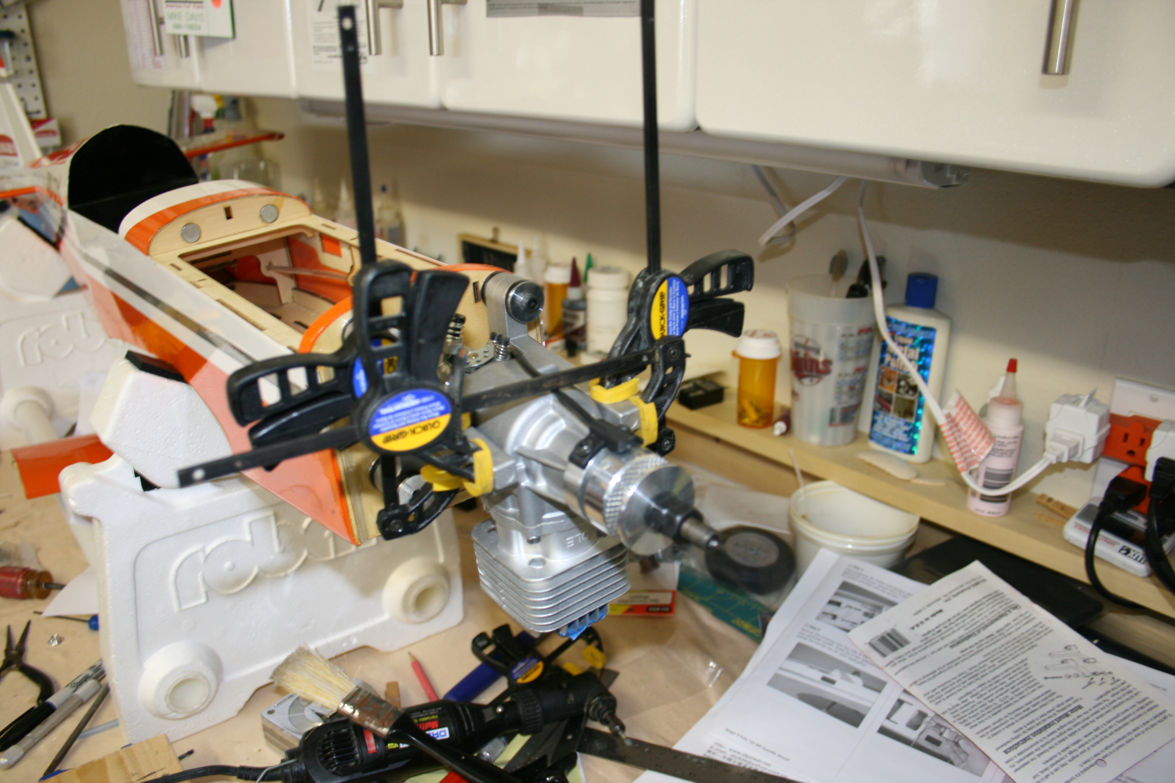
It has been good weather here in Oklahoma lately, so flying has been on the agenda. However with 30 mph gusts this weekend, flying was hazardous at best. I was able to get some more done on the Pulse and took some pictures along the way. I am on the engine (DLE 20) install and using the cushioned motor mounts from Dubro. Unfortunately, the template for the different motor types uses the mounts supplied with the ARF. It was tricky, but I was able to get them installed with only 1 extra hole  thanks to grosbeak's previous experiences. I haven't mounted the engine yet, but have read most of the threads on RCU about the Pulse. The instructions call for a 5 1/2" distance from the firewall to the engine backplate, but it is really only 5 1/4" and that is where mine will be. One of the pics shows the cowl installed for testing the distance and it does confirm the 1/4" difference.
You can also see from the pictures that when the t-nuts are installed and mounting bolts added, they protrude into the area where the access hatch sits. It is times like this that the person who invented the Dremel tool is one of my favorite people. I had to clean out the area where one of the tabs on the hatch plate enters the firewall, and open holes in the hatch front to accommodate the mounting bolts. This was done and now the next step is to install the engine. Will update further when completed.
I have also decided to save space the electronics area by moving to an optical switch/BEC combo and using only one battery for the electronic ignition. And, I am almost ready to spend the bucks for a J-Tec wrap around muffler. It is $80, but I plan to check the measurements between the cowl and the side of the muffler when installed. If possible I am trying to keep the whole cowl intact except for where the engine head and exhaust exit on the underneath side. I am guessing the normal size wrap around is too thick on the side where the box moves the exhaust to the canister, but if there is enough room, maybe I can have J-Tec fabricate one that is not as thick from exhaust port to cowl inside.


thanks to grosbeak's previous experiences. I haven't mounted the engine yet, but have read most of the threads on RCU about the Pulse. The instructions call for a 5 1/2" distance from the firewall to the engine backplate, but it is really only 5 1/4" and that is where mine will be. One of the pics shows the cowl installed for testing the distance and it does confirm the 1/4" difference.You can also see from the pictures that when the t-nuts are installed and mounting bolts added, they protrude into the area where the access hatch sits. It is times like this that the person who invented the Dremel tool is one of my favorite people. I had to clean out the area where one of the tabs on the hatch plate enters the firewall, and open holes in the hatch front to accommodate the mounting bolts. This was done and now the next step is to install the engine. Will update further when completed.
I have also decided to save space the electronics area by moving to an optical switch/BEC combo and using only one battery for the electronic ignition. And, I am almost ready to spend the bucks for a J-Tec wrap around muffler. It is $80, but I plan to check the measurements between the cowl and the side of the muffler when installed. If possible I am trying to keep the whole cowl intact except for where the engine head and exhaust exit on the underneath side. I am guessing the normal size wrap around is too thick on the side where the box moves the exhaust to the canister, but if there is enough room, maybe I can have J-Tec fabricate one that is not as thick from exhaust port to cowl inside.
Last edited by hookedonrc; 11-18-2013 at 07:29 AM.
 11-21-2013, 10:01 AM
#22
Thread Starter
It wasn't really. We had a local hobby shop that was going out of business about 1 1/2 years ago now. I saw it on the shelf and got a deal I could not pass up. It has been sitting on top of my fridge in the garage just waiting its turn to be put to use. Now it is time....
11-24-2013, 03:13 PM
#23
Thread Starter
Today it was time to get the engine installed. The DLE 20 went in easily on the Dubro cushioned mounts and the next step will be working the cowl. I had to drill out the firewall a little to allow for the carburetor mounting bolts to not touch the wall itself. You can see the areas on the firewall pictures. I really get excited when I put the engine in, it starts to make it look like an airplane. Before any of you freak out, the red plastic spinner backing is just for measurements. I plan to put on an aluminum one once I am at that point. Hope to get the cowl ready over the Thanksgiving weekend.


11-26-2013, 04:52 AM
#24
Thread Starter
It wasn't. We had a local hobby shop close in May of last year. The 125 was one of the last items just sitting on the shelf, so the owner lowered the price over $50 and I bought it. It has been on top of my fridge in the garage since then. I just got around to putting it together.
11-26-2013, 06:42 AM
#25
Senior Member
Today it was time to get the engine installed. The DLE 20 went in easily on the Dubro cushioned mounts and the next step will be working the cowl. I had to drill out the firewall a little to allow for the carburetor mounting bolts to not touch the wall itself. You can see the areas on the firewall pictures. I really get excited when I put the engine in, it starts to make it look like an airplane. Before any of you freak out, the red plastic spinner backing is just for measurements. I plan to put on an aluminum one once I am at that point. Hope to get the cowl ready over the Thanksgiving weekend.