


SIG Rascal 110 ARF Build Thread
 08-10-2015, 08:09 AM
#26
Senior Member
Thread Starter

I have seen these birds do some impressive maneuvers & with the high compression FA-180/FG-57 hybrid engine running on 15% nitro glow fuel W/CDI, it should be able to shoot vertical out of a hover. It makes a bit over 3HP on 15%. I opted for the 16oz fuel load for keeping the weight down W/low 15% or less nitro and short flights but for longer flights or high % nitro which increases fuel consumption, I have the option of a full 32oz fuel load.
Plans have changed so I won't get out to the shop today, but hope to continue tomorrow.
 09-14-2015, 09:51 AM
#27
Senior Member
Thread Starter
Lots of progress over the last 2 weeks albeit over several short sessions rather than a few marathon build efforts.
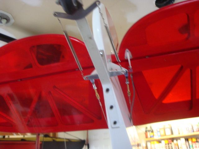
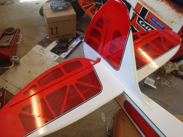
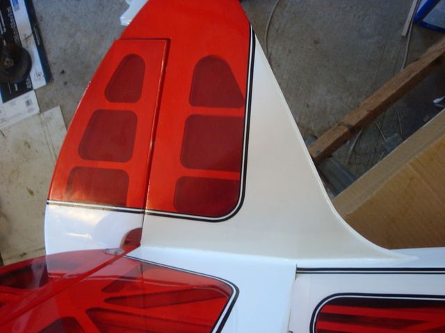
I finished installing the horizontal & vertical stabilizers & control surfaces along with the elevator push rod & rudder pull/pull cables..
A little white silicone tidied up the seam between the stabilizers & the top deck of the fuselage.
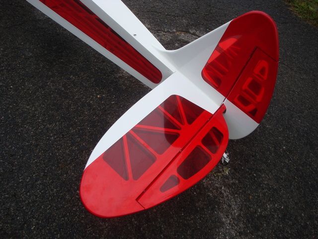
The elevator push rod modification worked out well.
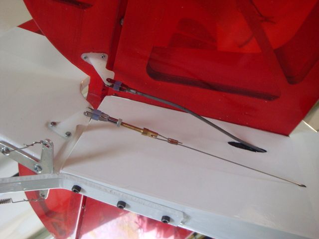
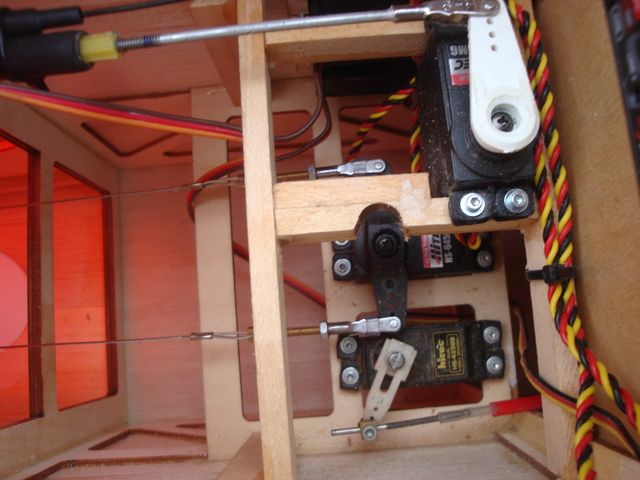
While hooking up the rudder pull/pull cables, I found a need to modify the elevator servo mount beam to allow easier access to the rudder servo horn screw. After several unsuccessful attempts to get at the horn screw, I glued a crutch on the inner side of the beam to allow me to grind radius into the beam for screw driver clearance.
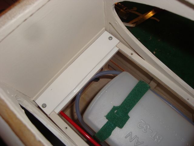
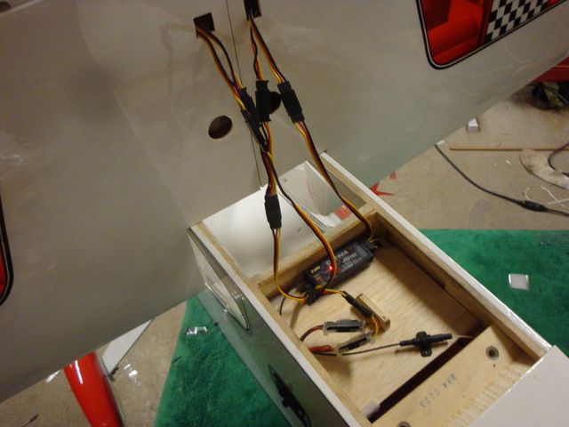
Next I addressed the installation of the Rx & Ignition switches. I used JR heavy duty switch/charge ports for their robust construction & reliability. I am using 2 battery packs & switch circuits for the RX for redundancy. Each circuit will have an 1100 mAh 6v AAA NiMh battery pack.
I started by cutting an additional hole for the second switch under the one provided.
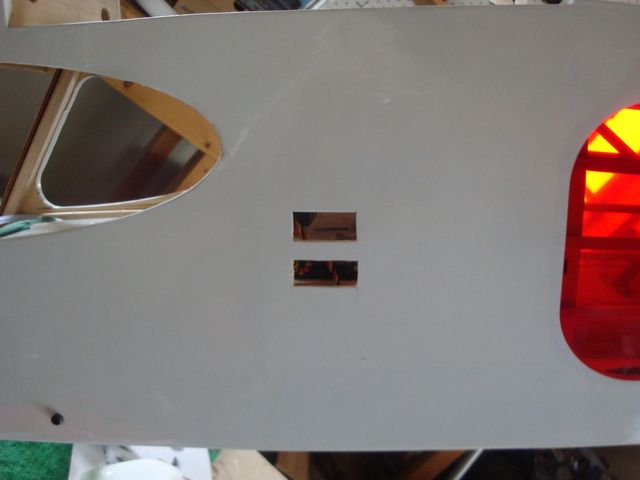
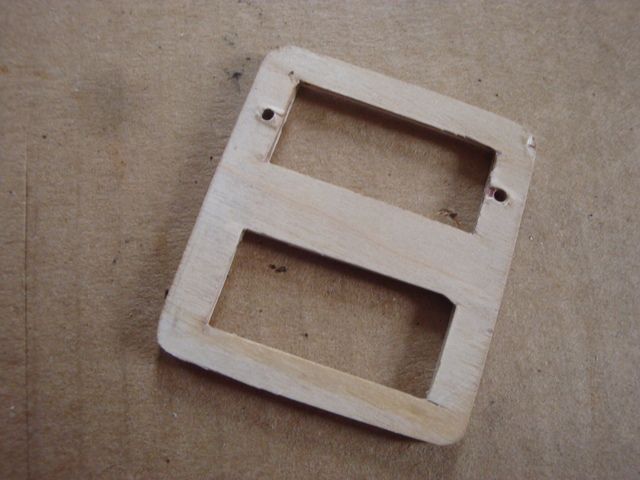
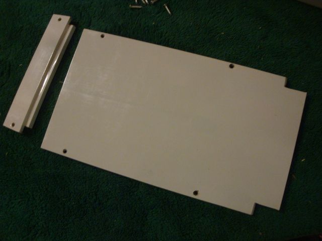
I made a back-up plate out of 1/16" birch ply with doublers glued to the edges where the screw would penetrate. I pre-drilled the holes for the top switch, but waited to position the switches in the fuselage before drilling the holes for the bottom switch.
I made a similar plate to secure the single switch for the ignition.
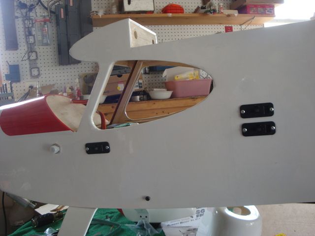
The wire leads on the JR switch were just about the perfect length to reach the ignition module & battery mounted behind the firewall.
In the next post I will go over the cockpit interior & cowl details.
I finished installing the horizontal & vertical stabilizers & control surfaces along with the elevator push rod & rudder pull/pull cables..
A little white silicone tidied up the seam between the stabilizers & the top deck of the fuselage.
The elevator push rod modification worked out well.
While hooking up the rudder pull/pull cables, I found a need to modify the elevator servo mount beam to allow easier access to the rudder servo horn screw. After several unsuccessful attempts to get at the horn screw, I glued a crutch on the inner side of the beam to allow me to grind radius into the beam for screw driver clearance.
Next I addressed the installation of the Rx & Ignition switches. I used JR heavy duty switch/charge ports for their robust construction & reliability. I am using 2 battery packs & switch circuits for the RX for redundancy. Each circuit will have an 1100 mAh 6v AAA NiMh battery pack.
I started by cutting an additional hole for the second switch under the one provided.
I made a back-up plate out of 1/16" birch ply with doublers glued to the edges where the screw would penetrate. I pre-drilled the holes for the top switch, but waited to position the switches in the fuselage before drilling the holes for the bottom switch.
I made a similar plate to secure the single switch for the ignition.
The wire leads on the JR switch were just about the perfect length to reach the ignition module & battery mounted behind the firewall.
In the next post I will go over the cockpit interior & cowl details.
Last edited by SrTelemaster150; 09-14-2015 at 11:38 AM.


 09-14-2015, 11:14 AM
#29
Senior Member
Thread Starter
09-14-2015, 11:15 AM
#30
Senior Member
Thread Starter
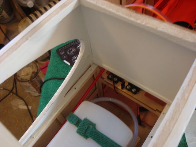
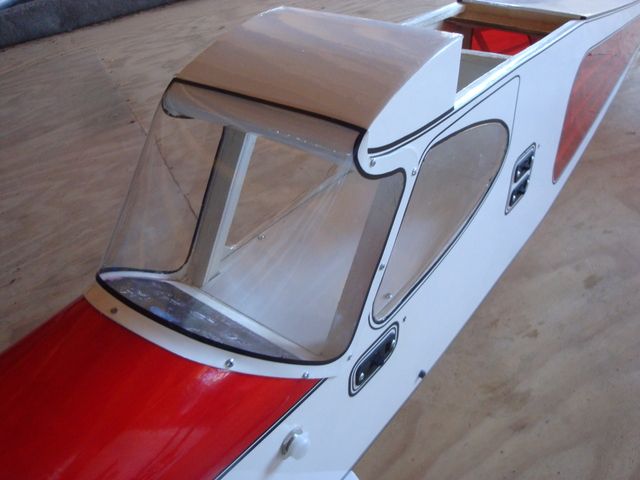
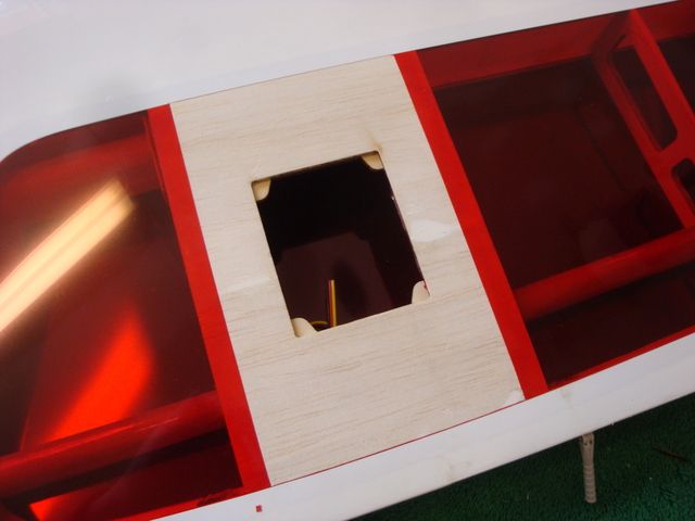
I started out by painting an exposed, easily visible area of the cockpit with some interior latex paint I had on hand.
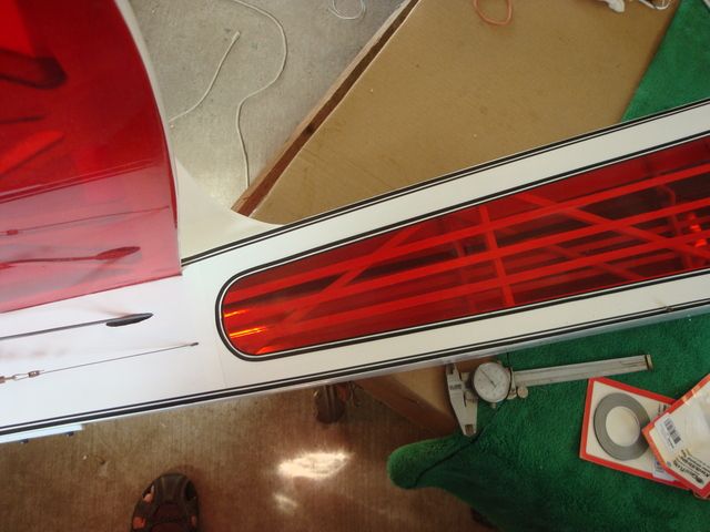
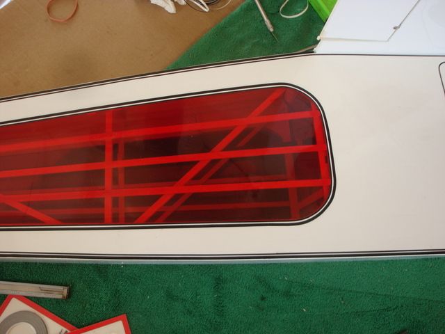
I then covered the 2 piece cockpit deck with white Ultracote.
I installed the rear deck portion fist.
Followed by the main deck portion.
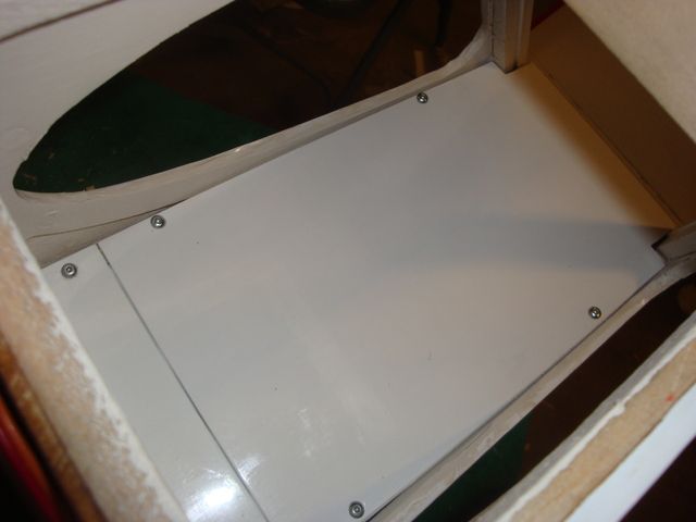
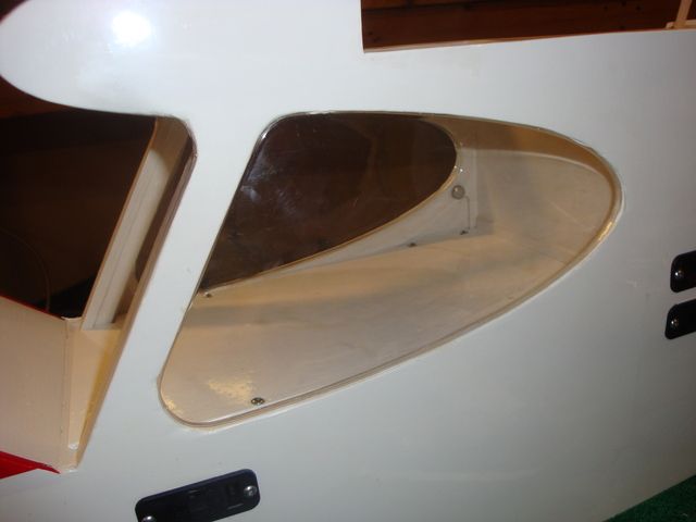
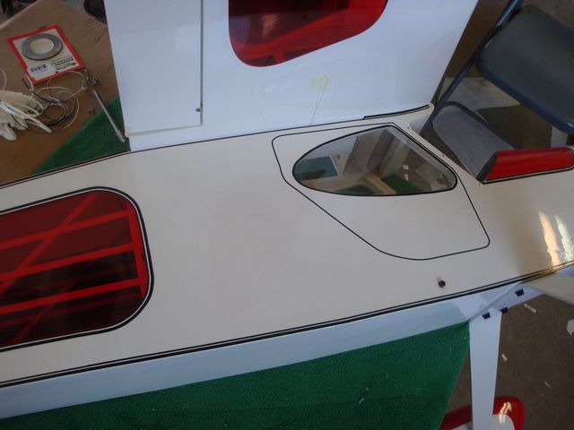
I opted to keep the side windows removable to allow easier removal of the deck for access to the fuel tank, plumbing & ignition switch. I trimmed some of the lip from the bottom of the window as well as the lower front corner. This allowed me to slip the flange behind the sides of the deck. The front bottom corners needed trimmed to allow manipulating the window into the slots cut into the windshield "A" pillar in the now tight confines.
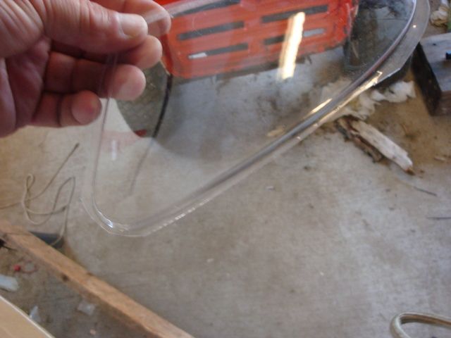
After some fiddling, the windows were coaxed into place.
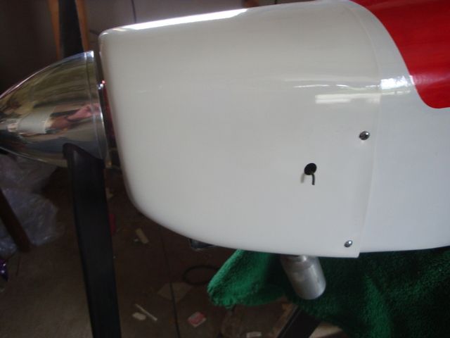
Next, I started work on some cowl details.
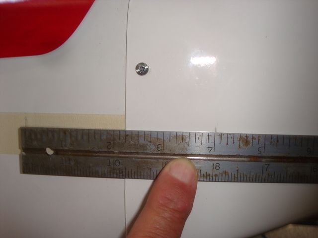
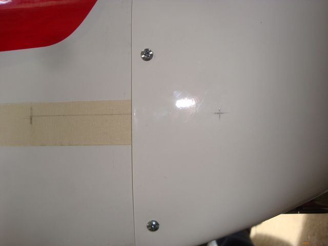
First, I placed some masking tape on both sides of the fuselage in the general line of where the high speed needle extension &low peed needle access hole would be located. I drew a line & marked a spot 4" from the center of the carburetor barrel.
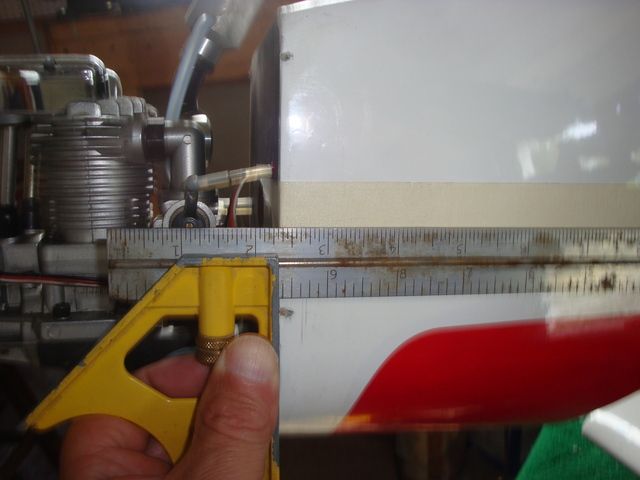
After installing the cowl, I used that line & mark to transpose the location of the barrel C/L on both sides of the cowl.
 \
\
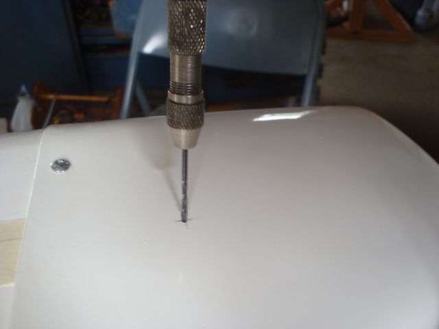
I then used a 1/16" drill in a pin vise to drill a pilot hole.
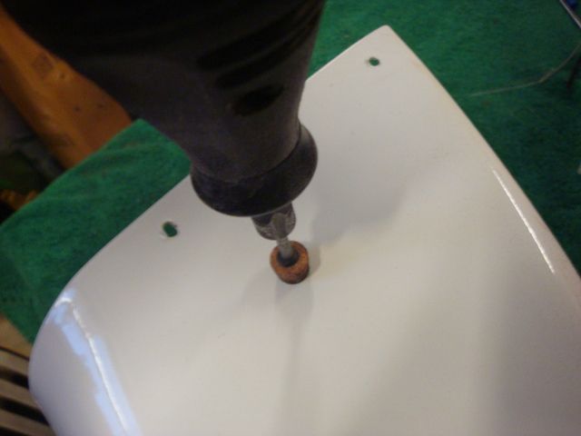
The holes where enlarged with a tapered stone in a Dremel tool.
Here is the HSN extension nearly perfectly centered in the hole.
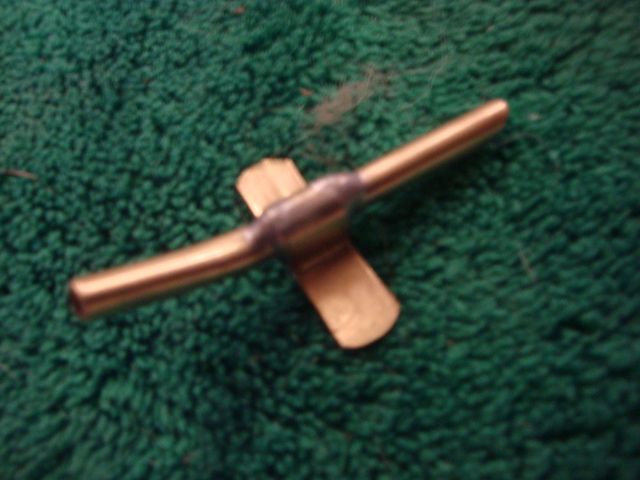
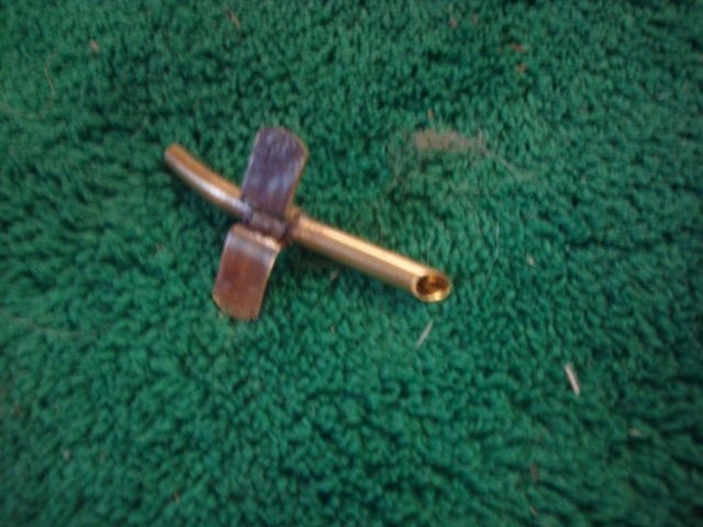
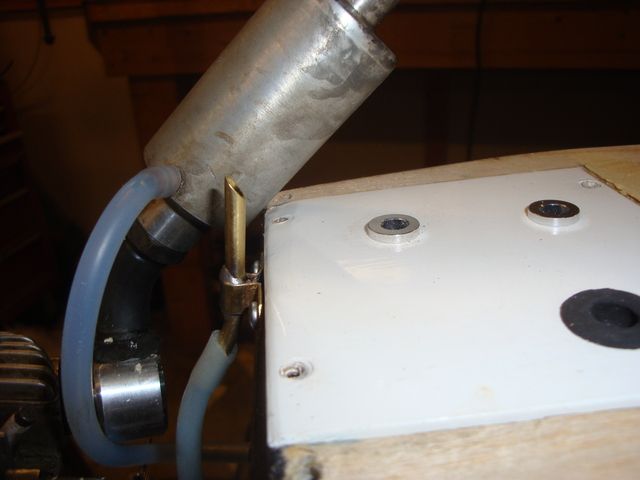
Even though the leaned burn of the CDI results in less mess, I wanted to provide a hard mounted breather tube to prevent the silicone breather tube from whipping around in the prop wash & spraying gunk all over the bottom of the fuselage. I flattened out some 3/16" brass tube, wrapped it around some 1/8" brass tube & soldered it together. After bending & filing I ended up with a serviceable breather tube. Note the slight bend to allow easy insertion into the silicone tube & the rear facing "bologna" cut to help scavenge the blow-by oil out of the tube.
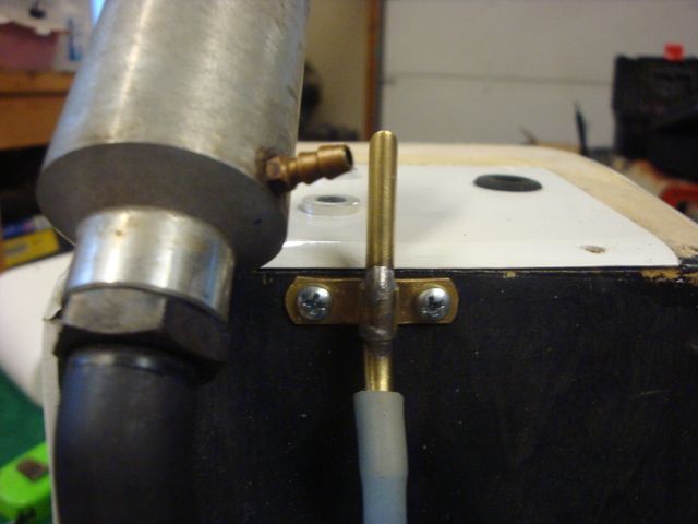
I mounted it just off center tucked in beside the muffler.
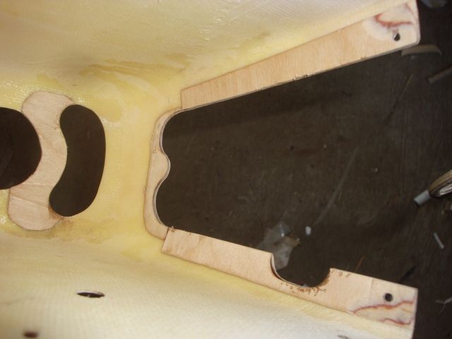
To prevent splitting I used thin CA to glue some 1/32 birch ply along the edges of the openings to reinforce some of the weak spots. I left the ply lap over the edges & ground it to shape with a coarse grit sanding drum in my Dremel tool.
In the next post I will go over gluing on the paper instrument panel, windshield installation & other finishing touches.
I then covered the 2 piece cockpit deck with white Ultracote.
I installed the rear deck portion fist.
Followed by the main deck portion.
I opted to keep the side windows removable to allow easier removal of the deck for access to the fuel tank, plumbing & ignition switch. I trimmed some of the lip from the bottom of the window as well as the lower front corner. This allowed me to slip the flange behind the sides of the deck. The front bottom corners needed trimmed to allow manipulating the window into the slots cut into the windshield "A" pillar in the now tight confines.
After some fiddling, the windows were coaxed into place.
Next, I started work on some cowl details.
First, I placed some masking tape on both sides of the fuselage in the general line of where the high speed needle extension &low peed needle access hole would be located. I drew a line & marked a spot 4" from the center of the carburetor barrel.
After installing the cowl, I used that line & mark to transpose the location of the barrel C/L on both sides of the cowl.
\I then used a 1/16" drill in a pin vise to drill a pilot hole.
The holes where enlarged with a tapered stone in a Dremel tool.
Here is the HSN extension nearly perfectly centered in the hole.
Even though the leaned burn of the CDI results in less mess, I wanted to provide a hard mounted breather tube to prevent the silicone breather tube from whipping around in the prop wash & spraying gunk all over the bottom of the fuselage. I flattened out some 3/16" brass tube, wrapped it around some 1/8" brass tube & soldered it together. After bending & filing I ended up with a serviceable breather tube. Note the slight bend to allow easy insertion into the silicone tube & the rear facing "bologna" cut to help scavenge the blow-by oil out of the tube.
I mounted it just off center tucked in beside the muffler.
To prevent splitting I used thin CA to glue some 1/32 birch ply along the edges of the openings to reinforce some of the weak spots. I left the ply lap over the edges & ground it to shape with a coarse grit sanding drum in my Dremel tool.
In the next post I will go over gluing on the paper instrument panel, windshield installation & other finishing touches.
Last edited by SrTelemaster150; 09-14-2015 at 11:34 AM.
09-14-2015, 11:18 AM
#31
Senior Member
Thread Starter
I wanted to wait all of the fuselage work was finished before installing the windshield.
After checking the preliminary balance to determine if I would need to mount battery aft, I found that the fuselage was ever so slightly nose heavy before then RX battery packs were placed.
Since I had access to place the battery over about 12" of fuselage behind then recommended CG, I decided to recovered the bottom of the fuselage & finish things up. After doing that, I covered the ignition module hatch & installed it.
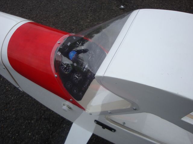
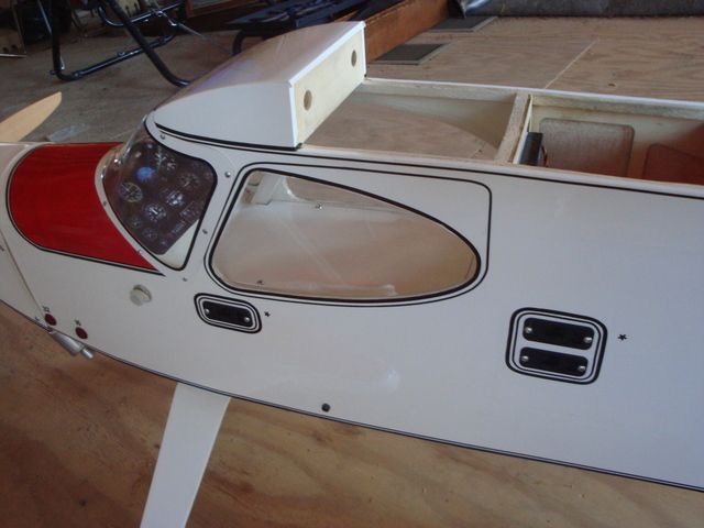
Now that I was done flopping the fuselage around on the work table, I glued the paper instrument panel on & installed the windshield using 6 additional screws from what the plans called for.
The fuselage is now about 99.9% complete. I still need to replace the cheap Hobby King (overflow ports) fuel dots that don't function properly with some PSP Manufacturing red anodized fuel dots.
I also need to coat the plywood cowl reinforcements with finishing epoxy & the cowl got some CA runs on the outside so I will probably sand it & repaint it to.
All it really lacks now are the wings & I have some modification in mind for them including paper tubes to hide the servo leads, reverse wiring one of the flap servos, custom length "Y' harness for the flaps, custom length servo extensions for the ailerons & I have to modify the servo hatches slightly to accommodate the the low profile servos that are slightly wider than the standard servos the hatches are designed for. I also need to make some other wire harness for the Rx hook-ups.
At some time I want to install a red blinking LED indicator for the ignition circuit as well as fabricate a circuit isolator board for the dual Rx circuits with blinking LED indicators for each circuit. That can wait until after the airframe is airworthy though.
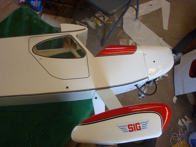
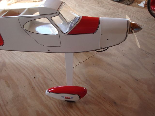
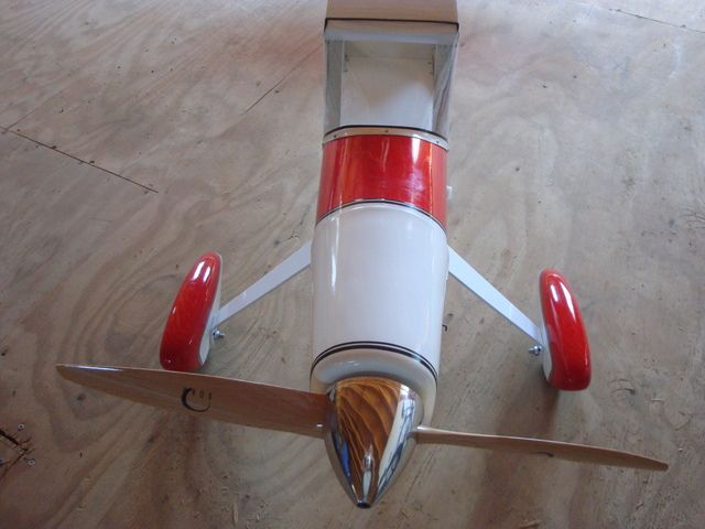
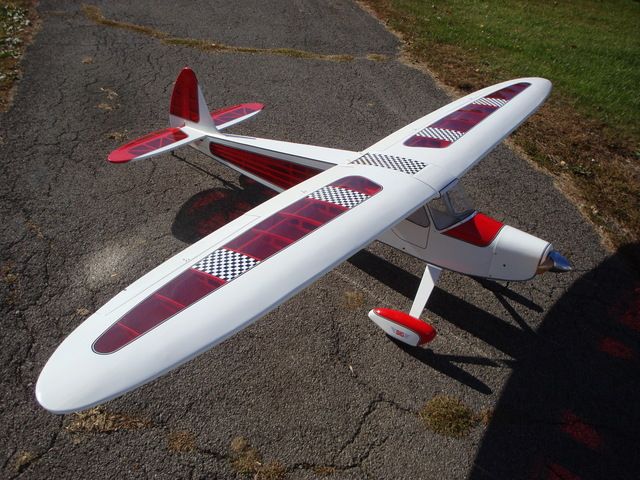
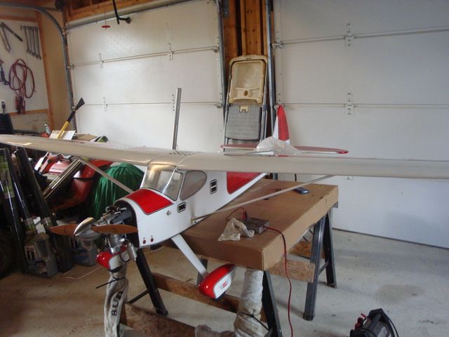
In the mean time, here is how she sits right now.
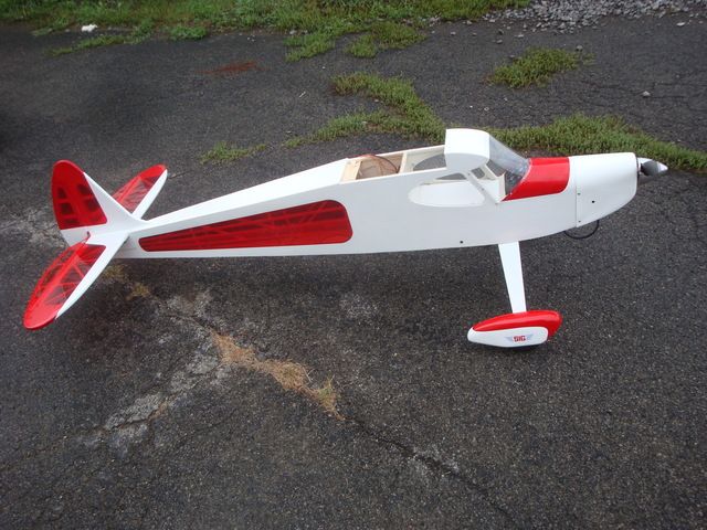
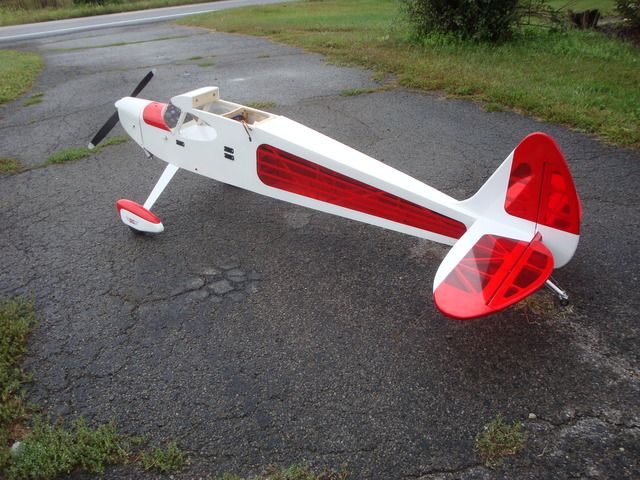
It won't be long now.
After checking the preliminary balance to determine if I would need to mount battery aft, I found that the fuselage was ever so slightly nose heavy before then RX battery packs were placed.
Since I had access to place the battery over about 12" of fuselage behind then recommended CG, I decided to recovered the bottom of the fuselage & finish things up. After doing that, I covered the ignition module hatch & installed it.
Now that I was done flopping the fuselage around on the work table, I glued the paper instrument panel on & installed the windshield using 6 additional screws from what the plans called for.
The fuselage is now about 99.9% complete. I still need to replace the cheap Hobby King (overflow ports) fuel dots that don't function properly with some PSP Manufacturing red anodized fuel dots.
I also need to coat the plywood cowl reinforcements with finishing epoxy & the cowl got some CA runs on the outside so I will probably sand it & repaint it to.
All it really lacks now are the wings & I have some modification in mind for them including paper tubes to hide the servo leads, reverse wiring one of the flap servos, custom length "Y' harness for the flaps, custom length servo extensions for the ailerons & I have to modify the servo hatches slightly to accommodate the the low profile servos that are slightly wider than the standard servos the hatches are designed for. I also need to make some other wire harness for the Rx hook-ups.
At some time I want to install a red blinking LED indicator for the ignition circuit as well as fabricate a circuit isolator board for the dual Rx circuits with blinking LED indicators for each circuit. That can wait until after the airframe is airworthy though.
In the mean time, here is how she sits right now.
It won't be long now.
Last edited by SrTelemaster150; 09-14-2015 at 11:31 AM.
09-14-2015, 11:35 AM
#32
I like to to add a breathing tube to my 4 cycle powered airplanes except I use a brass strap to clamp it the muffler with the outlet dumping into the exhaust path to blow it clear of the aircraft. I got the idea from a retired gentleman at one of the local fields. He had them on all his airplanes and they were simple to build. The strap was formed around a steel drill bit so the brass tub was under the strap as well as soldiered to it. A screw and nut clamped it around the muffler.
09-15-2015, 10:48 AM
#33
Senior Member
Thread Starter
By the time I do the tail feathers I will have used most of a full 36' roll of 1/16" & 1/8" tape. I still have the other side of the fuselage & the wings to do.
I think I will need a least 3 more rolls. That's a total of 5 rolls of both, 180' of each!
Last edited by SrTelemaster150; 09-15-2015 at 10:50 AM.
09-16-2015, 07:11 AM
#35
Senior Member
Thread Starter
Worked for 2 1/2 hours in the garage this morning. Very tedious work, but worth it I think.
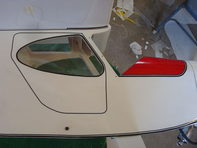
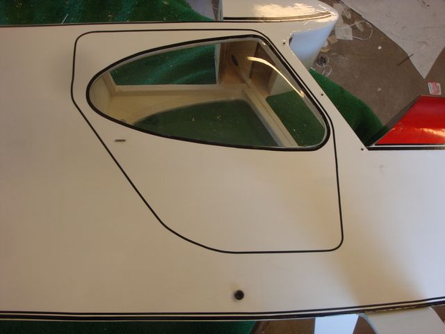
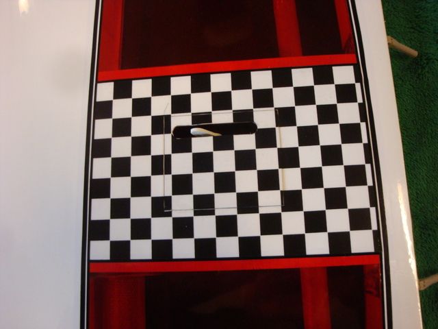
I re-worked the door outline. eliminating the square corner on the top front & taking out a slight dogleg near the bottom front corner of the window. I used a large "T" pin to simulate a door latch.
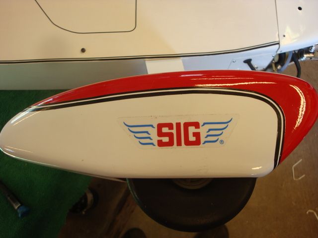
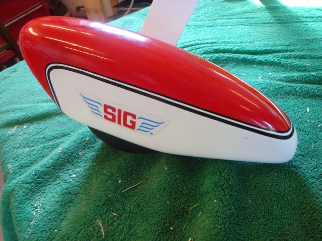
I think the striping on the wheel pants came out well..
I need to finish the port side of the fuselage & continue the bottom stripes around the cowl after I give it a few coats of paint to repair the CA over-runs.
Then, I can get the servos mounted in the wings & stripe them.
I re-worked the door outline. eliminating the square corner on the top front & taking out a slight dogleg near the bottom front corner of the window. I used a large "T" pin to simulate a door latch.
I think the striping on the wheel pants came out well..
I need to finish the port side of the fuselage & continue the bottom stripes around the cowl after I give it a few coats of paint to repair the CA over-runs.
Then, I can get the servos mounted in the wings & stripe them.
09-26-2015, 11:19 AM
#37
Senior Member
Thread Starter
I wrapped up some details on the fuselage. It is now complete & I can start on the wings.
1st off, I made a revision to the 32 oz/16 oz overflow tubes. The cheap Hobby King fuel dots didn't really work & were prone to pulling out of the fuel line leaving it stranded inside the fuselage. My 1st & last purchase from Hobby King. Yeah they were less than $3, but junk isn't a bargain no matter what the price.
I found these HERE for $5.99 ea (4 for $20)
They securely grip the fuel line, they securely snap into place and more importantly, they have enough reach to place them in the side of the fuselage where I originally intended.
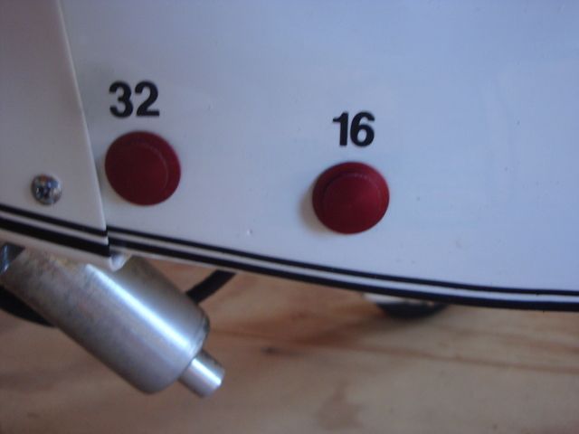
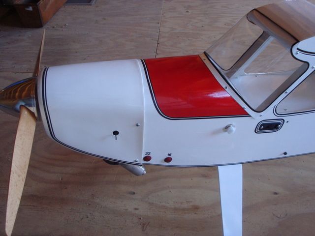
I used some Coverite 1/4" numbers to label the appropriate overflow line for the fuel level @ overflow.
I also did some pin striping around the switch/charge ports & used a black asterisk to designate the negative lead at the top. I am getting some red graphics to further identify the positive lead at the bottom with a red asterisk.
I gave the cowl a coat of white Lustercote & continued the pin stripe along the bottom edge of the fuselage onto & around the top of the cowl.
Now, for the most challenging detail!
I was not at all satisfied with the way that the thin plastic windshield buckled at the rear edges when the screws securing it where snugged down.
I cut some pieces of 1/32" ply & CA'ed them to the edges.
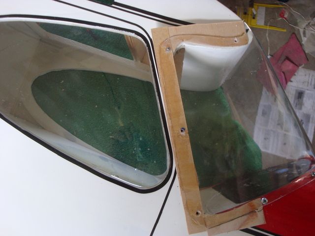
The small portion extending from the bottom corner forward to the 1st screw was tapered to allow a smooth transition
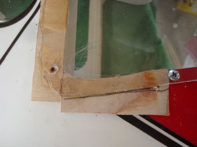
I left ample material hanging over the edges to allow ease in handling & gluing. I then trimmed the excess material with a pair of scissors & sanded the edges flush with the plastic.
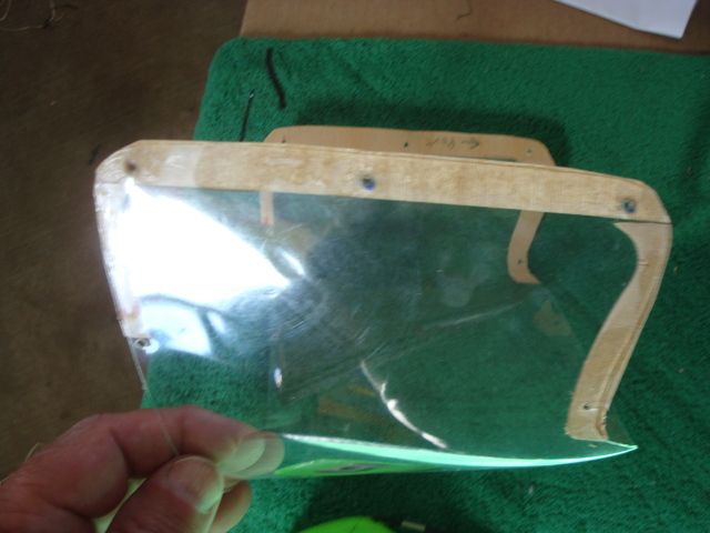
After masking off the windshield to paint the perimeter "frame" & some 1/8" pinstripe tape to dress up the edge of the paint line, I think it came out quite well. No more buckling.
Time to clean up the mess in the shop. The floor is covered with masking tape, pinstripe tape backing, paper towels, etc.
The wings will not take so long as I only have 2 revisions in mind.
One is a modification to the servo trays to accommodate the low profile servos, the other is a Kraft paper tubes to conceal the servo leads in the transparent wing bays.
1st off, I made a revision to the 32 oz/16 oz overflow tubes. The cheap Hobby King fuel dots didn't really work & were prone to pulling out of the fuel line leaving it stranded inside the fuselage. My 1st & last purchase from Hobby King. Yeah they were less than $3, but junk isn't a bargain no matter what the price.
I found these HERE for $5.99 ea (4 for $20)
They securely grip the fuel line, they securely snap into place and more importantly, they have enough reach to place them in the side of the fuselage where I originally intended.
I used some Coverite 1/4" numbers to label the appropriate overflow line for the fuel level @ overflow.
I also did some pin striping around the switch/charge ports & used a black asterisk to designate the negative lead at the top. I am getting some red graphics to further identify the positive lead at the bottom with a red asterisk.
I gave the cowl a coat of white Lustercote & continued the pin stripe along the bottom edge of the fuselage onto & around the top of the cowl.
Now, for the most challenging detail!
I was not at all satisfied with the way that the thin plastic windshield buckled at the rear edges when the screws securing it where snugged down.
I cut some pieces of 1/32" ply & CA'ed them to the edges.
The small portion extending from the bottom corner forward to the 1st screw was tapered to allow a smooth transition
I left ample material hanging over the edges to allow ease in handling & gluing. I then trimmed the excess material with a pair of scissors & sanded the edges flush with the plastic.
After masking off the windshield to paint the perimeter "frame" & some 1/8" pinstripe tape to dress up the edge of the paint line, I think it came out quite well. No more buckling.
Time to clean up the mess in the shop. The floor is covered with masking tape, pinstripe tape backing, paper towels, etc.
The wings will not take so long as I only have 2 revisions in mind.
One is a modification to the servo trays to accommodate the low profile servos, the other is a Kraft paper tubes to conceal the servo leads in the transparent wing bays.
Last edited by SrTelemaster150; 09-27-2015 at 03:42 AM.
09-28-2015, 10:59 AM
#40
Senior Member
Thread Starter
If you want 32 oz uncap the 32 oz line only. While the muffler line won't overflow when filling to 16 oz, it will when filling to the full 32 oz. The 32 oz overflow is merely "T"ed into the muffler (vent) line.
The muffler line is convenient to get to so it can be clamped W/hemostats. I want to recover excess fuel W/O contamination W/burned lube in the muffler & return it to be used. If recovery isn't desired, the overflow will run out of the muffler when the tank is filled to the full 32 oz capacity if nothing is done.
The following is how it was plumbed before I got the better fuel dots & located them in the side of the fuselage.
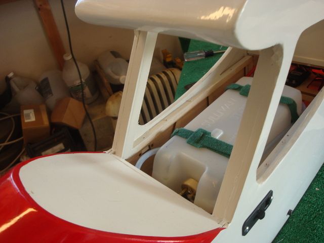
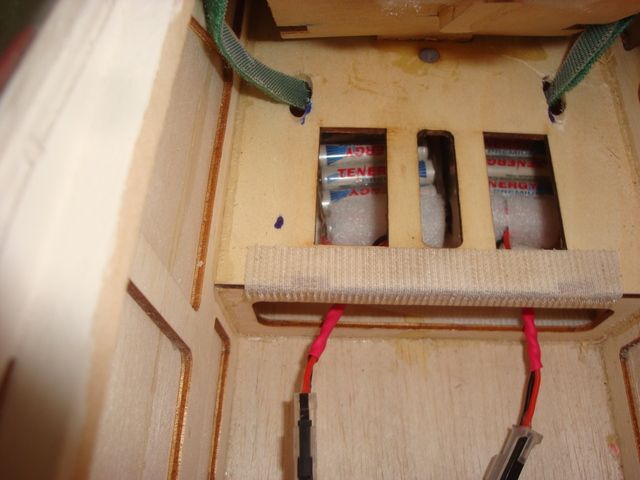
Now we address the fuel tank & plumbing the duel level overflow lines.
I uses 3 tank lines. The 2 on the top are the standard clunk & vent lines but the one in the center bottom is an overflow line that barely goes into the tank just beyond the stopper. Its purpose is to allow 1/2 of the 32oz tank to be filled to a consistent 16oz.
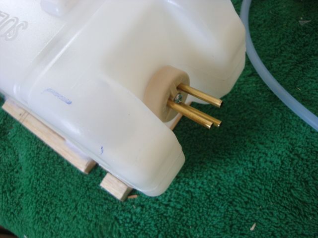
The vent line is "T"ed & the 2 lines exit the hatch under the chin.
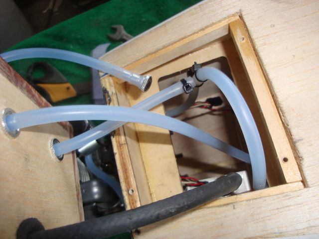
The rear line overflows at just a smidge over 16oz, the front line is the full 32oz overflow through the vent.
I uses 3 tank lines. The 2 on the top are the standard clunk & vent lines but the one in the center bottom is an overflow line that barely goes into the tank just beyond the stopper. Its purpose is to allow 1/2 of the 32oz tank to be filled to a consistent 16oz.
The vent line is "T"ed & the 2 lines exit the hatch under the chin.
The rear line overflows at just a smidge over 16oz, the front line is the full 32oz overflow through the vent.
Last edited by SrTelemaster150; 09-28-2015 at 11:18 AM.
10-03-2015, 03:50 PM
#41
Senior Member
Thread Starter
I opted for Hitec HS-77BB Low Profile Servos for the ailerons & flaps. They are 1 oz lighter than standard analog servos & at 77 oz-in, (6v) they have 35% more TQ than standard servos.
Even though they have considerably less depth, they are slightly longer & wider than the HS-425BB. I know they are meant to be mounted flat, (which I abhor) they still offered the best torque/weight package in a reasonably priced analog servo.
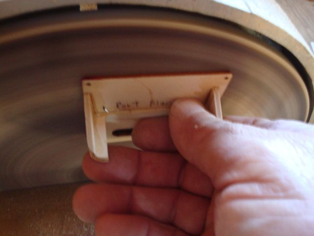
This required the servo trays to be modified slightly, but when I started working on the mount beams, I found the original construction sorely lacking in structural integrity. While the slots milled into the tray decks where 1/4", the mount beams where fabricated out of 5mm plywood & the glue appeared to be some sort of hot melt adhesive that did not achieve a good bond. Some of the mount beam could be broken free with some moderate twisting by hand & they all came free with a (very) little work with an Exacto knife.
Here are the original mount beams after removal. Note how the adhesive parted from the tray deck along with the mount beams.

If you plan on putting your Rascal 110 through high stress aileron maneuvers (as I am) you might want to have a look at the servo tray construction. Mine was one of the 1st batch from Vietnam so this issue might have been addressed by now.
I fabricated an insert for my table saw to use my 1/2" Dado blade. I sandwiched 4 layers of 1/4" poplar plywood with sacrificial layers of 1/8" birch plywood on the outside to prevent flaking of the plies.
Note the flaking on the 1/8 outer layers.
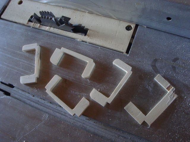
I used Scotch double sided tape (poster tape) to hold the layers together.
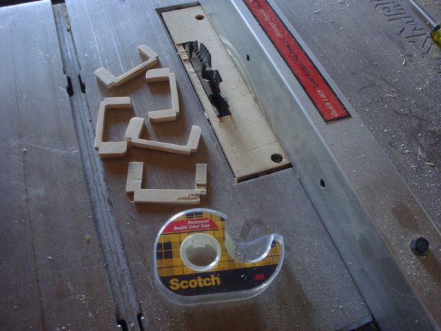
After finishing the shape with a disc sander & rasps, it was easy enough to use a #11 Exacto knife blade to separate the layers.
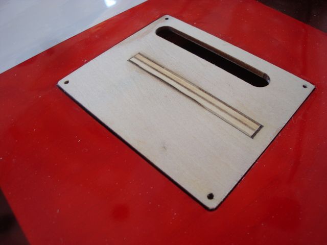
The tongue that mortised into the deck was left slightly long. After assembly with 30 minute epoxy & ample curing time this is what I had.
A quick swipe on the disc sander brought the surfaces flush
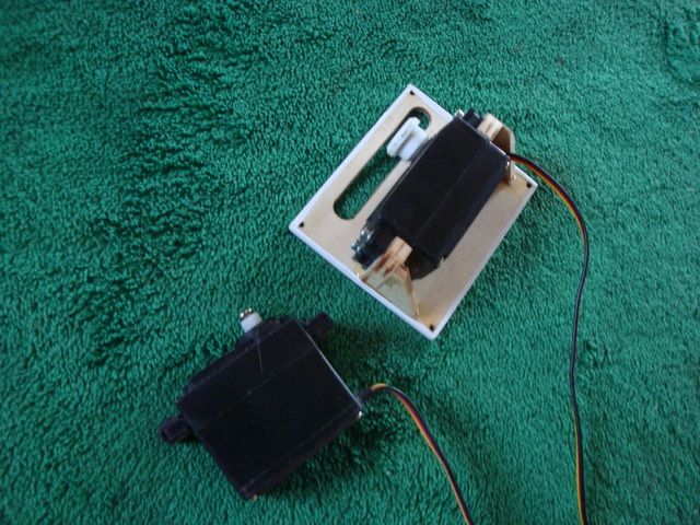
Here is the finished product with the low profile HS-77BB servo mounted and the standard size HS-425BB servo next to it for comparison.
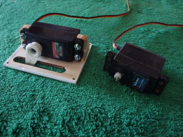
Since I had no Transparent red Ultracote, I had to do something different for the finish color scheme. I will go into that in the next post later this evening.
Even though they have considerably less depth, they are slightly longer & wider than the HS-425BB. I know they are meant to be mounted flat, (which I abhor) they still offered the best torque/weight package in a reasonably priced analog servo.
This required the servo trays to be modified slightly, but when I started working on the mount beams, I found the original construction sorely lacking in structural integrity. While the slots milled into the tray decks where 1/4", the mount beams where fabricated out of 5mm plywood & the glue appeared to be some sort of hot melt adhesive that did not achieve a good bond. Some of the mount beam could be broken free with some moderate twisting by hand & they all came free with a (very) little work with an Exacto knife.
Here are the original mount beams after removal. Note how the adhesive parted from the tray deck along with the mount beams.
If you plan on putting your Rascal 110 through high stress aileron maneuvers (as I am) you might want to have a look at the servo tray construction. Mine was one of the 1st batch from Vietnam so this issue might have been addressed by now.
I fabricated an insert for my table saw to use my 1/2" Dado blade. I sandwiched 4 layers of 1/4" poplar plywood with sacrificial layers of 1/8" birch plywood on the outside to prevent flaking of the plies.
Note the flaking on the 1/8 outer layers.
I used Scotch double sided tape (poster tape) to hold the layers together.
After finishing the shape with a disc sander & rasps, it was easy enough to use a #11 Exacto knife blade to separate the layers.
The tongue that mortised into the deck was left slightly long. After assembly with 30 minute epoxy & ample curing time this is what I had.
A quick swipe on the disc sander brought the surfaces flush
Here is the finished product with the low profile HS-77BB servo mounted and the standard size HS-425BB servo next to it for comparison.
Since I had no Transparent red Ultracote, I had to do something different for the finish color scheme. I will go into that in the next post later this evening.
10-03-2015, 03:53 PM
#42
Senior Member
Thread Starter
Since I had no transparent red Ultracote to cover the servo trays, I had to come up with something.
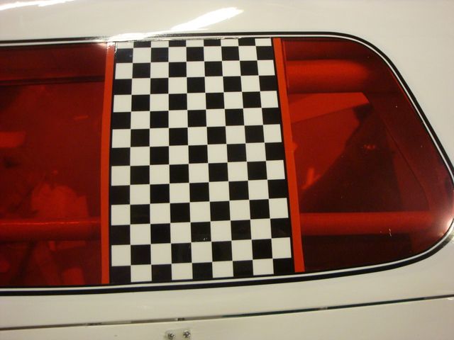
What I did have was white Ultracote & some left-over black/clear checkerboard Monokote trim sheet.
First I removed a 4 1/4" strip of the transparent red to allow a 4 1/2" strip of white Ultracote to be used as a base for the checkerboard.
After covering the area & the servo trays with white, I applied the checkerboard with Windex to allow some shifting around. I applied the checkerboard with the servo tray in place & cut along the edges of the tray after the trim had adhered.
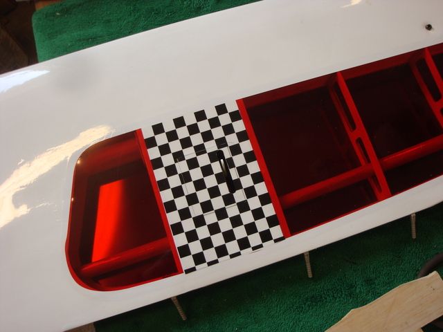
After the Windex had dried & there was good adhesion of the trim sheet, even though I hadn't done the aileron tray yet, I couldn't resist applying some pinstripe tape to see what the finished scheme would look like.
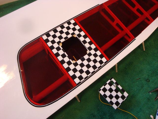
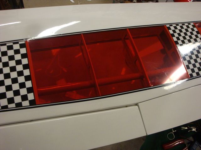
I had already made a pair of 1/2" tubes from 32" Kraft paper wrapped around a 1/2" dowel rod. The purpose was to hide the servo leads in the transparent wing bays. Since I was kinda "winging it", I didn't take pictures. I will do so when I work on the starboard wing.
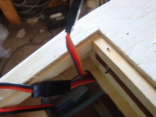
If you look closely at some of the pictures previously posted, you can see the tube just ahead of the trailing edge. I opted to place the tubes aft to allow the servo leads to exit in the radio compartment behind the rear cockpit bullhead. There will be no servo leads visible in the cockpit area.
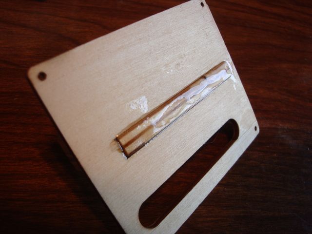
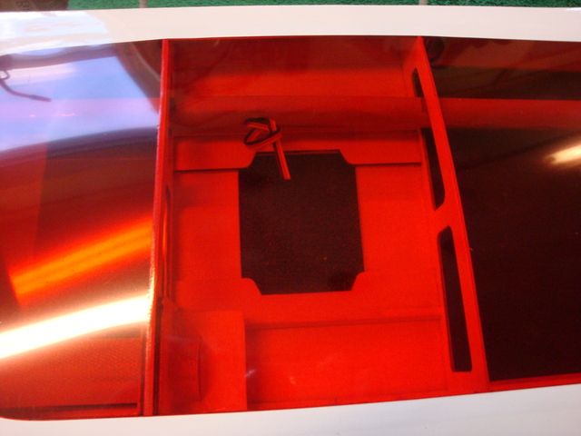
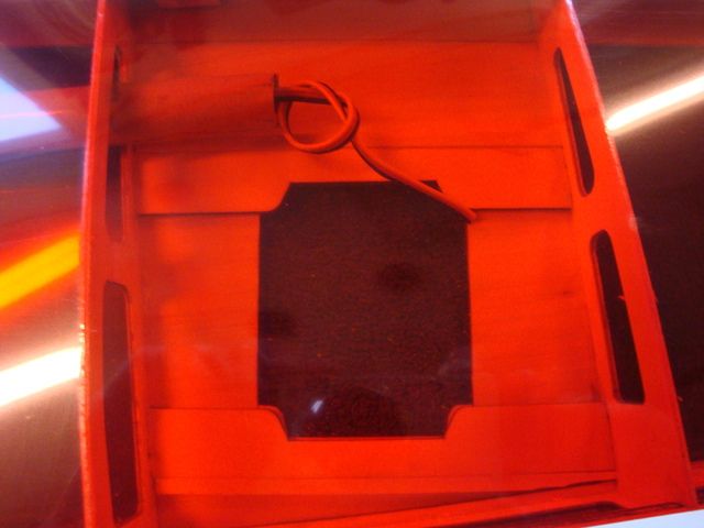
In the mean time, here are some pictures of the exit points as seen through the transparent film from the top of the wing. You can see the servo leads already fished through the tubes awaiting the installation of the connectors.
1st, the exit at the flap servo hatch.
The end of the tube at the aileron servo hatch.
I have some black/white checkerboard Monokote trim sheet on order to apply directly over transparent servo bays to hide the servos from view. I am so pleased with the looks of the bottom of the wing panel checkerboard treatment that I am going to do the same on the top.
What I did have was white Ultracote & some left-over black/clear checkerboard Monokote trim sheet.
First I removed a 4 1/4" strip of the transparent red to allow a 4 1/2" strip of white Ultracote to be used as a base for the checkerboard.
After covering the area & the servo trays with white, I applied the checkerboard with Windex to allow some shifting around. I applied the checkerboard with the servo tray in place & cut along the edges of the tray after the trim had adhered.
After the Windex had dried & there was good adhesion of the trim sheet, even though I hadn't done the aileron tray yet, I couldn't resist applying some pinstripe tape to see what the finished scheme would look like.
I had already made a pair of 1/2" tubes from 32" Kraft paper wrapped around a 1/2" dowel rod. The purpose was to hide the servo leads in the transparent wing bays. Since I was kinda "winging it", I didn't take pictures. I will do so when I work on the starboard wing.
If you look closely at some of the pictures previously posted, you can see the tube just ahead of the trailing edge. I opted to place the tubes aft to allow the servo leads to exit in the radio compartment behind the rear cockpit bullhead. There will be no servo leads visible in the cockpit area.
In the mean time, here are some pictures of the exit points as seen through the transparent film from the top of the wing. You can see the servo leads already fished through the tubes awaiting the installation of the connectors.
1st, the exit at the flap servo hatch.
The end of the tube at the aileron servo hatch.
I have some black/white checkerboard Monokote trim sheet on order to apply directly over transparent servo bays to hide the servos from view. I am so pleased with the looks of the bottom of the wing panel checkerboard treatment that I am going to do the same on the top.
Last edited by SrTelemaster150; 10-04-2015 at 02:55 AM.
10-06-2015, 01:32 PM
#43
Senior Member
Thread Starter
Dusted off my soldering skills today & did some electrical work.
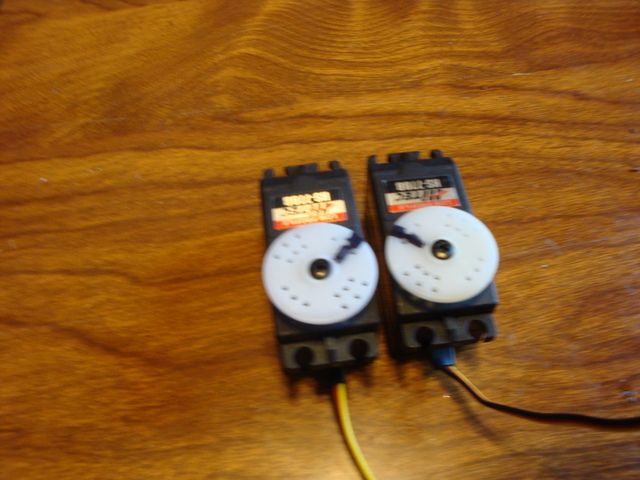
1st off I needed to reverse one of the HS-77BB servos for use on the starboard flap. I didn't want to use a reversing "Y" harness so I Googled it I found a YouTube video that showed a Hitec servo being reversed internally.
I used a fine tip soldering iron & it was quite easy. All that needs to be done is swap the green & red (outside) leads on the potentiometer (left) and the yellow tan leads on the motor (right)
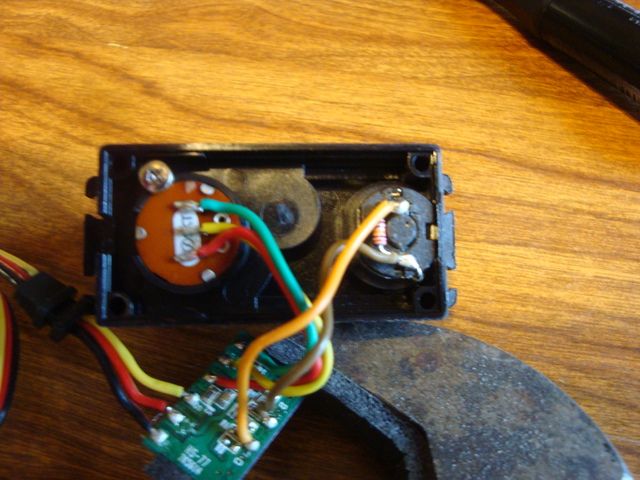
Here is the video, but this guy used a large soldering gun & I would not have attempted the job with such an unwieldy tip.
https://www.youtube.com/watch?v=EK_FdRTenl0 Here is the standard HS-77BB servo along side of the reversed at center. (note the black lines)
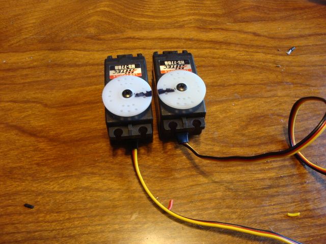
Here they are when the flaps are deployed W/the Tx.
This is a 15 minute job & I would never use a reversing "Y" harness since it is so easy to do if you have a fine tip soldering iron & some decent soldering skills..
Next, I tackled fabricating my own "Y" harnesses.
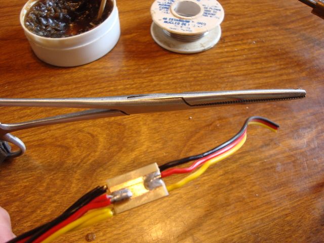
I used the "PC board method". I picked up a small sheet of 1/6" copper clad PC board & "PCB Etchant Solution" @ Radio Shack.
I cut a 4" x 3/8" strip with my motorized miter box. After dressing up the saw cut edge on the disc sander I drew a 1/8" stripe down the center of one side W/a black permanent marker. On the back side I drew 1/8" stripes down either side, leaving a 1/8" of bare copper in the center. I placed it in a shallow plastic tray in 1/4" of Etchant Solution. It took a little longer that the 20 minutes in the directions most likely due to the cool temperature of the solution.
After about 45 minutes I was left with what I needed. I cut pieces about 1/2" long.
1st I soldered the red leads to the side W/the copper stripe down the center.
On the flip side I soldered the yellow & black leads to the stripes on either edge.
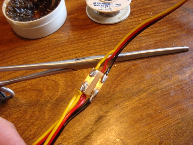
After applying a bit of electronics grade silicone to each end of the boards, I cut a piece of shrink wrap & heat shrunk it to insulate & protect the board.
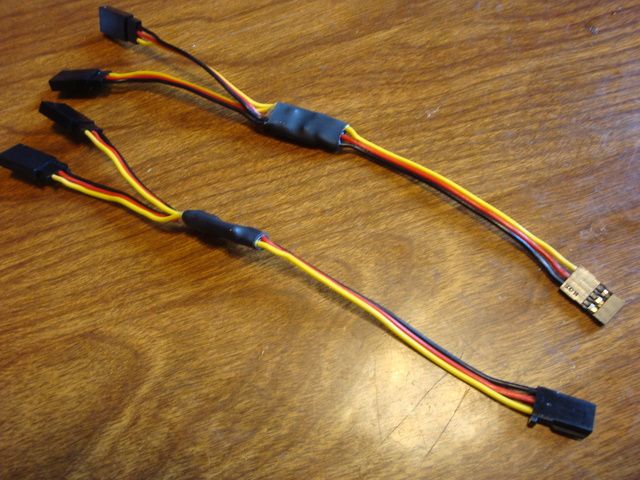
When I made the extensions for the flap & aileron servos, I used Futaba "J" & Hitec/JR ends respectively. This will make it impossible to get the leads mixed up on assembly.
I fabricated the "Y" harness on top W/Hitec/JR connectors, the one on the bottom Futaba "J" connectors. The Rx will accept either.
HERE IS A THREAD that I found here on RCG about this method.
Right now, the port wing is complete except for the trim/pin striping on the top and the push-rods for the flaps/ailerons. I am opting to make them from 2-56 rod since they are so short. The ones that came with the ARF are way oversize. I like to use a "Z" bend on the servo end to allow mechanical differential to be built into the ailerons. The "Z" bend allow the servo arm to rotate much farther forward than a clevis. I orient "center" position of the servo at 45 degrees forward to accomplish differential.
I'll tackle the starboard wing tomorrow & hope to have it completed.
1st off I needed to reverse one of the HS-77BB servos for use on the starboard flap. I didn't want to use a reversing "Y" harness so I Googled it I found a YouTube video that showed a Hitec servo being reversed internally.
I used a fine tip soldering iron & it was quite easy. All that needs to be done is swap the green & red (outside) leads on the potentiometer (left) and the yellow tan leads on the motor (right)
Here is the video, but this guy used a large soldering gun & I would not have attempted the job with such an unwieldy tip.
https://www.youtube.com/watch?v=EK_FdRTenl0 Here is the standard HS-77BB servo along side of the reversed at center. (note the black lines)
Here they are when the flaps are deployed W/the Tx.
This is a 15 minute job & I would never use a reversing "Y" harness since it is so easy to do if you have a fine tip soldering iron & some decent soldering skills..
Next, I tackled fabricating my own "Y" harnesses.
I used the "PC board method". I picked up a small sheet of 1/6" copper clad PC board & "PCB Etchant Solution" @ Radio Shack.
I cut a 4" x 3/8" strip with my motorized miter box. After dressing up the saw cut edge on the disc sander I drew a 1/8" stripe down the center of one side W/a black permanent marker. On the back side I drew 1/8" stripes down either side, leaving a 1/8" of bare copper in the center. I placed it in a shallow plastic tray in 1/4" of Etchant Solution. It took a little longer that the 20 minutes in the directions most likely due to the cool temperature of the solution.
After about 45 minutes I was left with what I needed. I cut pieces about 1/2" long.
1st I soldered the red leads to the side W/the copper stripe down the center.
On the flip side I soldered the yellow & black leads to the stripes on either edge.
After applying a bit of electronics grade silicone to each end of the boards, I cut a piece of shrink wrap & heat shrunk it to insulate & protect the board.
When I made the extensions for the flap & aileron servos, I used Futaba "J" & Hitec/JR ends respectively. This will make it impossible to get the leads mixed up on assembly.
I fabricated the "Y" harness on top W/Hitec/JR connectors, the one on the bottom Futaba "J" connectors. The Rx will accept either.
HERE IS A THREAD that I found here on RCG about this method.
Right now, the port wing is complete except for the trim/pin striping on the top and the push-rods for the flaps/ailerons. I am opting to make them from 2-56 rod since they are so short. The ones that came with the ARF are way oversize. I like to use a "Z" bend on the servo end to allow mechanical differential to be built into the ailerons. The "Z" bend allow the servo arm to rotate much farther forward than a clevis. I orient "center" position of the servo at 45 degrees forward to accomplish differential.
I'll tackle the starboard wing tomorrow & hope to have it completed.
Last edited by SrTelemaster150; 10-06-2015 at 04:45 PM.
11-05-2015, 06:07 AM
#45
Senior Member
Thread Starter
It's been some time since I updated the progress. There has been considerable work getting things finished up & sorting out a few gremlins.
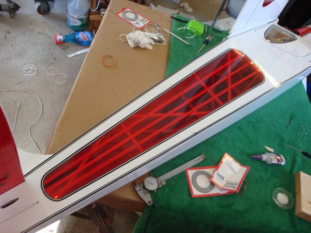
First off is the trim treatment to the tops of the wings. I used white/black check trim to match the bottoms of the servo bays. I opted for the white/black trim since it was applied over the red transparent Ultracote.
Unfortunately, some of the ribs weren't perfectly square with the spar line & the discrepancy could be "read" along the edges of the checkerboard. I used my stripe cutting machine to cut some 5/16" stripes from red Ultracate trim strip.
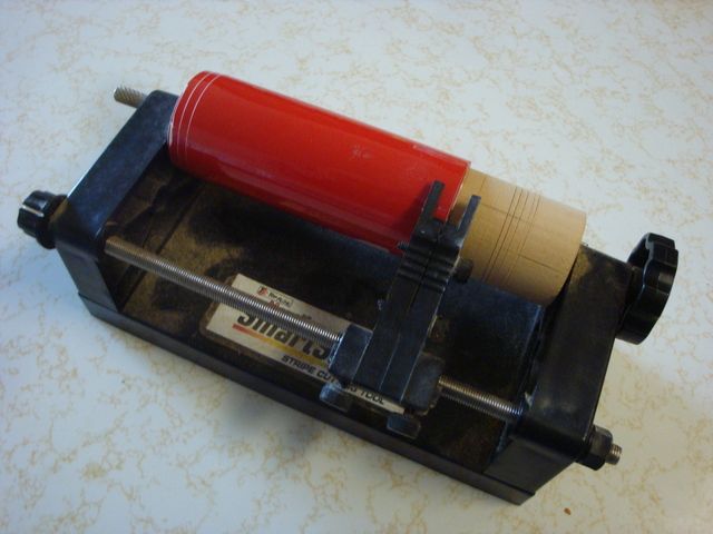
The color of the red trim sheet mimicked the look of the transparent red over raw balsa quite well.
This picture shows the paper tube for the servo leads quite well.
I fabricated some "Y" harnesses, one of them a double "Y" to join the 2 battery circuits as well as channel 7 on the Rx. I also made a 1/16" balsa deck to keep the wires out of the servo arms. The deck is held in place with Velcro as is the Rx.
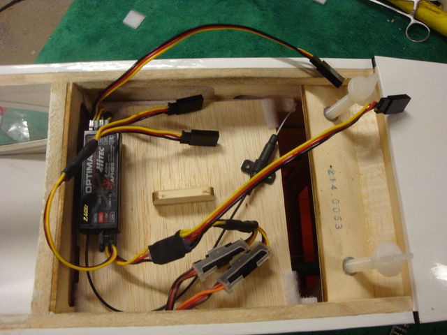
The leads are just the right length to allow convenient connection to the wing servos.
Since the airframe was still slightly tail heavy, I applied velcro hook under the fuel tank just ahead of the CG location & mounted the two "AAA" 1000 mAh 6v NiMh packs there. It was a challenge to get the Velcro applied, but a bit of patience paid off.
Finally, she's ready to fire up & test the powerpalnt.
Next up, chasing out the gremlins.
First off is the trim treatment to the tops of the wings. I used white/black check trim to match the bottoms of the servo bays. I opted for the white/black trim since it was applied over the red transparent Ultracote.
Unfortunately, some of the ribs weren't perfectly square with the spar line & the discrepancy could be "read" along the edges of the checkerboard. I used my stripe cutting machine to cut some 5/16" stripes from red Ultracate trim strip.
The color of the red trim sheet mimicked the look of the transparent red over raw balsa quite well.
This picture shows the paper tube for the servo leads quite well.
I fabricated some "Y" harnesses, one of them a double "Y" to join the 2 battery circuits as well as channel 7 on the Rx. I also made a 1/16" balsa deck to keep the wires out of the servo arms. The deck is held in place with Velcro as is the Rx.
The leads are just the right length to allow convenient connection to the wing servos.
Since the airframe was still slightly tail heavy, I applied velcro hook under the fuel tank just ahead of the CG location & mounted the two "AAA" 1000 mAh 6v NiMh packs there. It was a challenge to get the Velcro applied, but a bit of patience paid off.
Finally, she's ready to fire up & test the powerpalnt.
Next up, chasing out the gremlins.
11-05-2015, 06:09 AM
#46
Senior Member
Thread Starter
The 1st problem I encountered when I fired up the FA-180 was that the 90 degree exhaust adapter would allow the exhaust muffler to move outboard. No mater how many times I adjusted it & tightened down the jam nut it would still move outboard. The puzzling thing is, the rotation was clockwise so the adapter was actually screwing itself tighter! This was a very bad omen as it was obvious that the aluminum was stretching & would soon fail.
This ended up being a blessing in disguise.
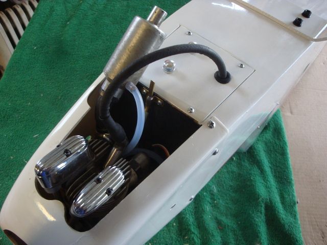
I modified a stock Saito exhaust pipe, increasing the bend to about 80 degrees. I cut 2 notches with a hacksaw 3/4 of the way through, bent the pipe to close the gaps & widened the notches/bent the pipe again until I got the angle I needed. Some acetylene welding & grinding gave me a finished product. The stock exhaust pipe on top, the modified on the bottom.
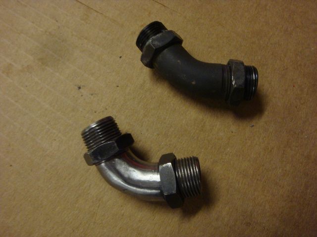
The resulting angle was an improvement over that of the adapter set-up allowing easier access to the ignition module hatch screws.
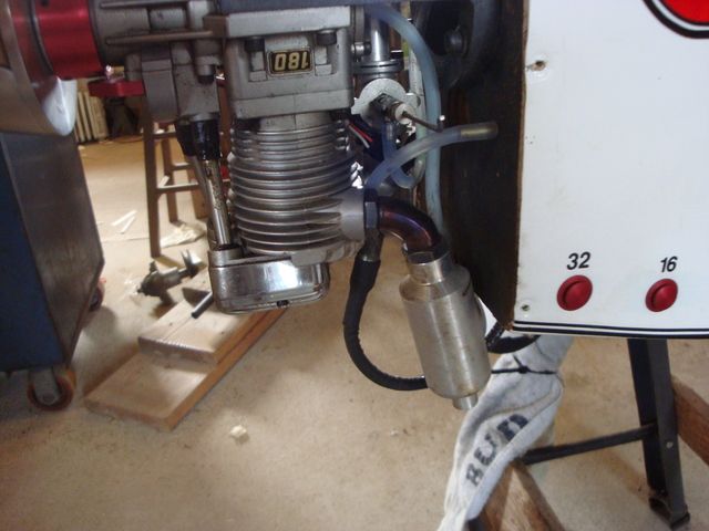
The picture makes it look like the muffler is against the firewall, but there's about 1/4" of clearance.
This ended up being a blessing in disguise.
I modified a stock Saito exhaust pipe, increasing the bend to about 80 degrees. I cut 2 notches with a hacksaw 3/4 of the way through, bent the pipe to close the gaps & widened the notches/bent the pipe again until I got the angle I needed. Some acetylene welding & grinding gave me a finished product. The stock exhaust pipe on top, the modified on the bottom.
The resulting angle was an improvement over that of the adapter set-up allowing easier access to the ignition module hatch screws.
The picture makes it look like the muffler is against the firewall, but there's about 1/4" of clearance.
11-05-2015, 06:12 AM
#47
Senior Member
Thread Starter
I had issues with the FA-180/FG-57 CDI hybrid power output.
It would only pull about 7500 RPM @ WOT with an 18X8 prop. That is about FA-150 power. I popped the rear cover off & inspected the rear main bearing.
It only had a slight patina & was smooth, but the cage was not following the balls around the inner race. I pulled the engine, installed new bearings ran it on the engine stand. 8250 RPM (about 3.3 HP) with the 18x8 Dynathrust propeller! Dependable idle was 1100 RPM on the stand with the cylinder mounted upright.
I mounted the engine on the airframe & that's when I stated having problems with getting a dependable idle with smooth transition. If I would lean out the LSN for good idle, it would spit & fart on transition.
I fought it for 2 days until I remembered something I learned a while back.
A dab of SILICONE GREASE IN THE MCDANIELS PLUG SOCKET allowed me to lean down the LSN & still get smooth transition from 1500 RPM idle.
Taxi tests done yesterday at the Seaway Valley Modelaires flying site allowed me to further refine the idle/transition by leaning out the LSN about 1/8 turn more. We also tested fuel delivery at vertical, inverted *& nose down attitude at various throttle positions & transition. I held the plane while a friend jockeyed the throttle. It has enough power to go vertical from a hover on the upline!
I still had an issue with the throttle trim being way too sensitive gaining several hundred RPM with a single blip on the digital throttle trim. Last night. I investigated the EPA on channel 3 & found that it was turned way down to compensate for an overly long servo arm. I shortened up the arm & it now has nearly 125% EPA W/O stalling the servo. I also adjusted the pushrod so that the idle position had the arm back beyond 45* so that there would be less linear motion on the pushrod for a given amount of rotational motion of the servo arm.
If the weather hold for today I'm going to the field for more taxi tests & possibly a maiden flight if my expert pilot friend can make it out. I'm still too shaky to risk flying an unproven aircraft. A little more stick time will restore my confidence so for right now I will have to observe & fly on a buddy box.
11-05-2015, 06:50 PM
#49
Senior Member
Thread Starter
Took the rascal 110 to one of the local fields this afternoon & had the instructor maiden the Rascal 110. It flies like a big puddy tat. Takes off smartly @ about 1/3 throttle. It looks so graceful in the sky.The instructor loved it. The guy has agreed to take me up with my buddy box so I can log some stick time & get rid of the butterflies.
We had a minor mishap on landing. The plane ran off the edge of the runway into some 2nd growth hay. It sheared 3 of the 10-32 nylon bolts on the main gear (as designed) & scuffed up the wheel pants. I'm going to touch them up, but will leave them off for the time being.
It only needed a few clicks of right aileron trim to fly hands off.
11-05-2015, 08:45 PM
#50

Outstanding! Sounds like another good Rascal has taken to the air. Congrats!!