


ThunderTiger Rare Bear
 01-06-2016, 06:51 AM
#1926

I never liked external linkages with scale machines, (although have to bite the bullet on ailerons and flaps) as it "Uglies" them up a lot. Should have seen the trouble I got into fitting everything into the back of the N/P 53" A6M. Ouch!
Yours may just have been too fast a throttle increase and the requirement to keep the tail down for control would cause it to launch before it has enough airspeed. Been caught by that one a few times, mostly when doing maidens on planes new to the field.
Yours may just have been too fast a throttle increase and the requirement to keep the tail down for control would cause it to launch before it has enough airspeed. Been caught by that one a few times, mostly when doing maidens on planes new to the field.
 01-06-2016, 02:42 PM
#1927

Join Date: Dec 2005
Location: tehachapi,
CA
Posts: 215
Likes: 0
Received 0 Likes
on
0 Posts
it was the first time I flew it that close to sea level so yeah it accelerated a lot faster than what we had seen . I started making template to replace/add two 1/8" ply ribs,and a double layer of 3/16 ply gear blocks. the stock ones were made from several layers of 1/8" ply that wasn't even glued together.
01-07-2016, 06:20 AM
#1928
I'm sure you've seen these before, but if you have the time, make it like mine with ply ribs and one single mount plate. The assembly interlocks and supports the side of the retract, as well. Indestructible
If I remember my original ribs were soft balsa and true, not much glue to hold it all together.
If I remember my original ribs were soft balsa and true, not much glue to hold it all together.
Last edited by Cougar429; 01-07-2016 at 06:24 AM.
01-08-2016, 06:21 AM
#1930
That extra rib is more for side support of the retract. Eflites use alloy side plates that like stress even less than plastic.
The reason I used a ply mounting plate was to ensure the two pads were perfectly in line. Hard to do that when they are separate blocks.
The reason I used a ply mounting plate was to ensure the two pads were perfectly in line. Hard to do that when they are separate blocks.
01-19-2016, 05:31 PM
#1931
Well, after fudging around trying to see about moving the Rx and distribution center forward to allow for trimming down the side frames set it aside and started on the flaps. So far have one wing cut and am working on both flaps at the same time, using the one as a pattern for the second. These will be modified Fowler type that will allow air to flow up from the bottom over the flap. To do that I offset the front of the flap on a 45 degree angle and the hinge line will be below the wing slightly to allow for that travel. Still have not decided if the control will be hidden or not as this would have been much easier with the skins off.
Also doubled up the inner rib to leave some protection and better fit to the fuse sides.
Will have some pics later.
Also doubled up the inner rib to leave some protection and better fit to the fuse sides.
Will have some pics later.
 01-25-2016, 07:54 PM
#1933
Will do. Off to a friends tomorrow night to check out some hinge setups that will help. Nothing I came up using what I had around with filled me with confidence
In the meantime have measured and carved into the first wing to work on servo installation. At this point all will be internal, but set up so in worst case can quickly copy the aileron rigging with external control horns.
Only issue I can see is fitting the servo to the second wing as they will both turn the same direction. If too much trouble will dig out a reversing Y-lead from spares and check the geometry follows through the range. BAD if one flap extends more than the other at any deflection.
01-26-2016, 07:19 PM
#1934
Join Date: Dec 2005
Location: tehachapi,
CA
Posts: 215
Likes: 0
Received 0 Likes
on
0 Posts
I have in the past just flipped the one servo over and put the control horn in a different spot ,does not harm any thing . we found reversing "y" cords to cause big proplems with some radios. I just used another chn on mine and mixed it to the flaps. allows better adj if needed. also when you have the wing open add some glue to every thing you can get too inside there.
01-27-2016, 06:34 AM
#1935
Join Date: Mar 2014
Posts: 58
Likes: 0
Received 0 Likes
on
0 Posts
Plane fly tail heavy when I drop landing gear and running low on fuel.
Need to add some weight to the nose weight.
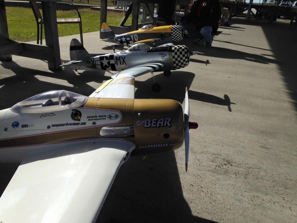
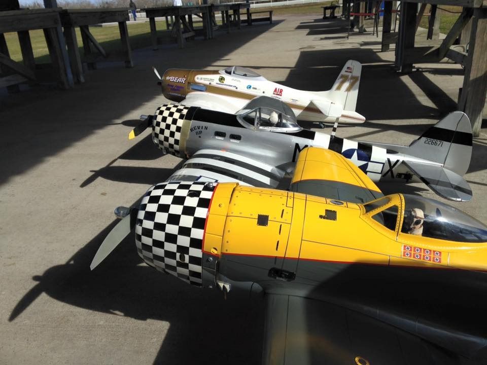
Here a flight of the Rare Bear racing TP P-47.
https://www.youtube.com/watch?v=cKaOBvam-e0
Need to add some weight to the nose weight.
Here a flight of the Rare Bear racing TP P-47.
https://www.youtube.com/watch?v=cKaOBvam-e0
Last edited by Stone17; 01-27-2016 at 06:37 AM.
 01-29-2016, 04:28 PM
#1939
Join Date: Dec 2005
Location: tehachapi,
CA
Posts: 215
Likes: 0
Received 0 Likes
on
0 Posts
I rebuilt my tail and used a "real" unidirectional fibered C/F tube for the spar .the stock spar was rolled cloth so only half of the fibers were providing the strength of the spar. also mounted the elev servo in the tail for a shorter push rod that wont cause flutter.
I got one wing fixed up on mine ....the other just needs some glue added. I found out the retract bearers are made from several 1/8" thick pieces of ply wood ...that was not even glued ,or laminated together

I got one wing fixed up on mine ....the other just needs some glue added. I found out the retract bearers are made from several 1/8" thick pieces of ply wood ...that was not even glued ,or laminated together
01-31-2016, 05:46 AM
#1940
Family down for the weekend so only had time to work on it for a few minutes. Took a pic of the wing in a pretty sad state as it has been cut open and hogged. Even with that, now that I know where the flap hinges will sit have to get in there to install some anchor points. Not sure if it will simply be easier to cut back the skin and patch it later.
The covering will be a patch job, as well for now as I will only invest in a complete redo if this proves to work.
I'll try and post some more pics soon.
The covering will be a patch job, as well for now as I will only invest in a complete redo if this proves to work.
I'll try and post some more pics soon.
02-03-2016, 09:02 PM
#1941
Join Date: Dec 2005
Location: tehachapi,
CA
Posts: 215
Likes: 0
Received 0 Likes
on
0 Posts
you'll love the flaps ,but don't do T&G with them deployed ...bring the flaps up be fore you add power or at least be ready as it will try to tip over on you . and don't cut power until right over the ground they make a lot of lift so it takes some power to come in on
02-07-2016, 03:03 PM
#1942
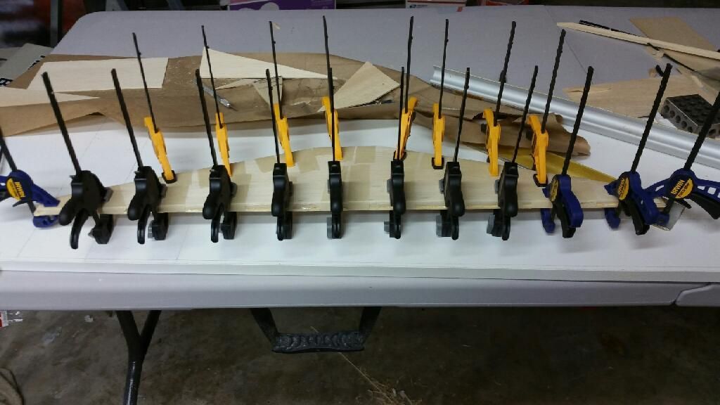
I had more time than planned to work on the Bear so made some serious progress. At this point I am only a few steps away from recovering both the wings and flaps.
One thing to mention is the back spar of the wing and the leading edge of the flaps are angled back 45 degrees spanwise with the lower edge being more forward. This is what gives the air the routing it needs as they deploy.
These pics are of the second wing. Once I had the pattern down building up the second was relatively simple. One change however was to add a fourth hinge point to balance out both sides of the activator rod attach. Those hinges are Hatch Hinges from H/K and I drilled out the plastic pins and replaced them with small brass bolts and nuts. Those bolts are just inserted for the pics.
With the flaps fully retracted the wing has a normal airfoil, but as they deploy the trailing edge arcs aft and down. This also increases the angle between the hinge and actuator pivots more to the vertical with approximately the same distance you would get with an external control arm. It's all in the geometry .
.
The more they deploy the more the front end opens up to allow airflow over the top, aka Fowler style, with fully deployed having a significant gap. The amount of max deployment and any elevator mixing will be determined by flight testing and the linkage rigged so at that point the servo arm will be line with the rod, relieving any stress on the servo.
NOTE: To get that action I had to mount the hinges on lite ply bosses. I will likely cover those separately before the wing to make things easier. Same with the flaps themselves.
I should add that with the angle of the inside of the ailerons had to do some creative carving on the flap ends to prevent interference with them partially deployed. Would have been much simpler if they were straight cut ends and always an option later.
Will have some more pics once the covering commences.
One thing to mention is the back spar of the wing and the leading edge of the flaps are angled back 45 degrees spanwise with the lower edge being more forward. This is what gives the air the routing it needs as they deploy.
These pics are of the second wing. Once I had the pattern down building up the second was relatively simple. One change however was to add a fourth hinge point to balance out both sides of the activator rod attach. Those hinges are Hatch Hinges from H/K and I drilled out the plastic pins and replaced them with small brass bolts and nuts. Those bolts are just inserted for the pics.
With the flaps fully retracted the wing has a normal airfoil, but as they deploy the trailing edge arcs aft and down. This also increases the angle between the hinge and actuator pivots more to the vertical with approximately the same distance you would get with an external control arm. It's all in the geometry
.The more they deploy the more the front end opens up to allow airflow over the top, aka Fowler style, with fully deployed having a significant gap. The amount of max deployment and any elevator mixing will be determined by flight testing and the linkage rigged so at that point the servo arm will be line with the rod, relieving any stress on the servo.
NOTE: To get that action I had to mount the hinges on lite ply bosses. I will likely cover those separately before the wing to make things easier. Same with the flaps themselves.
I should add that with the angle of the inside of the ailerons had to do some creative carving on the flap ends to prevent interference with them partially deployed. Would have been much simpler if they were straight cut ends and always an option later.
Will have some more pics once the covering commences.
Last edited by Cougar429; 02-07-2016 at 03:08 PM.
02-08-2016, 05:30 AM
#1944
Thanks. I just hope they hold up and work effectively, as this plane gains weight every time I look at it across the room.
What you can't see are the basswood cross braces that provide anchors the front hinge pieces. Each spans one rib to the next. You can just spot where the skin was replaced and blended in. Once the ply blocks were located I repeatedly poked the balsa to allow the CA to wick down to the basswood to tie the two together at more than just the screws.
Wish I could tell you the exact #. I had Robart struts till the end of last season and decided to try these I think I grabbed at the Toledo Show-can't remember- as they have slightly longer stroke, but what appears to be the capability to cut to different strut lengths.Originally intended for a P-51 or another scale project and were sitting in spares.
I believe they are similar to these from H/K:
http://www.hobbyking.com/hobbyking/s...yle_2pcs_.html
Last edited by Cougar429; 02-08-2016 at 05:59 PM.
02-08-2016, 04:19 PM
#1946
Join Date: Dec 2005
Location: tehachapi,
CA
Posts: 215
Likes: 0
Received 0 Likes
on
0 Posts
post #1851 pg #75 there is a link to a thread in R/C groups with some pics of my build . also post #1906 there is a pic and you can see the struts.
02-12-2016, 04:51 PM
#1947
Good news. Both wings are complete. Only need to find more of the correct screws to bolt the flap hinges down and will keep my eyes open. I know that little package of them is hidden somewhere.....
Worst case should be able to find something at the Toledo Show.
Taking a break to see if I can find out why and where my friends pumped OS 120 is leaking, then back on the fuse.
Worst case should be able to find something at the Toledo Show.
Taking a break to see if I can find out why and where my friends pumped OS 120 is leaking, then back on the fuse.
02-15-2016, 02:41 PM
#1949
My Feedback: (4)
Join Date: Apr 2008
Location: Orange, CA
Posts: 95
Likes: 0
Received 0 Likes
on
0 Posts
Good to see this Thread is still alive.... My bear has taken a long long nap... about a three year nap and is getting ready to come out of hibernation.... If i remember Correctly I've already made the upgrades in the tail feathers, moved the Servos into the wing and installed brass and carbon fiber spars, now i need to tear into the main Wings and replace Everything! lol, My bear is being Powered by a BVM 91 Ducted Fan Engine... Should be fun. 
02-15-2016, 03:32 PM
#1950
Not sure if that engine will work the best for this app. From my own experience they are timed to run in the high teens, something you likely will never see with a prop large enough to clear than large cowl, (safely that is!).
Dug into the fuse and took a chunk out of each side frame to give better access to the wing retainers. That meant I had to add basswood keels and side braces to make up for the loss of structure. Also meant I had to relocate the throttle servo which now resides below the power panel. That meant the cowl had to come off, etc. etc.....
At this point working on rerouting all the wiring so it still clears the C/F wing tube and looking at where and how to mount the 2.4 antennas so they are perpendicular and clear of any other electrical. Of course I don't have any extensions the right length for the flaps, but will rig something up to at least allow for programming the mixes.
I will have some pics up soon.
Last edited by Cougar429; 02-15-2016 at 03:38 PM.