


How to convert an ATX power supply to rc use
 04-21-2009, 03:58 PM
#151
Banned
My Feedback: (9)
Join Date: Dec 2001
Location: Newberry, FL
Posts: 5,925
Likes: 0
Received 0 Likes
on
0 Posts
ORIGINAL: eszaqsc
So I can get more at +12 volt line by making all of them paralel? (4x i ohm 10 watt in paralel)
So you basically have a 1 ohm 40 watt resistor on the 5 volt rail? That's what you get if you put two in series (2 ohms) and then parallel them with two more, which drops the resistance of the four back to 1 ohm. Only difference is you get the benefit of 40 watts of heat disipation. You should get the same reading with just one, but it might get a lot warmer.
 04-21-2009, 04:12 PM
#152
Senior Member

Join Date: Feb 2005
Location: Soddy Daisy, TN
Posts: 217
Likes: 0
Received 0 Likes
on
0 Posts
ORIGINAL: eszaqsc
So I can get more at +12 volt line by making all of them paralel? (4x i ohm 10 watt in paralel)
So I can get more at +12 volt line by making all of them paralel? (4x i ohm 10 watt in paralel)
The arrangement you have of resistors now is going to load the 5 volt rail about as much as you can load it, which will push the voltages up on all the rails, including the 12 volt rail, to just about their max. If you can't get as much as you need out of it with what you have, I'm afraid you may need to look for another source for whatever you're trying to power. Without major modifications, at 12.10 volts, it's giving you all it's got.
David
05-03-2009, 02:05 AM
#153
Junior Member
Join Date: May 2009
Location: Sydney, AUSTRALIA
Posts: 2
Likes: 0
Received 0 Likes
on
0 Posts
hi all,
i've followed all the instructions for the mod but can't get my PSU to start up. i've got the PS_ON green wire connected to a black (ground) wire, i've got the sense wire (light orange) attached to a orange 3.3v line and i've got a 10w 10ohm resistor connected to the red +5v line and to a black ground line. but get no joy!
i've check the purple line +5v standby, that works and when i flick the switch i can see the fan twitch a bit, so something is happening.
i've double checked for any other sense wires, but there aren't any. the 20 pin plug only has one pin with 2 wires going into it.
anybody got any ideas on what else i can try?
thanks,
kefa
05-03-2009, 09:18 AM
#154
Senior Member
Join Date: Feb 2005
Location: Soddy Daisy, TN
Posts: 217
Likes: 0
Received 0 Likes
on
0 Posts
1. Do you know for sure that the PSU was functional before you began converting it?
2. Have you checked the unit for voltage output on the 5 & 12 volt rails, or are you just watching the fan? The PSU could be working, but the fan could just be bad.
3. Have you checked to make sure there are none of the other wires shorted to ground? Make sure the binding posts, if you have installed them, aren't touching the case of the PSU. Check the wires on the reisitor to make sure they aren't touching the case where it's mounted. The twitching fan almost sounds like it's trying to come on, but senses a short and shuts down.
05-03-2009, 11:40 AM
#155
ORIGINAL: dmccormick001
The twitching fan almost sounds like it's trying to come on, but senses a short and shuts down.
The twitching fan almost sounds like it's trying to come on, but senses a short and shuts down.
andrew
05-05-2009, 06:25 PM
#156

Join Date: Sep 2002
Location: nowhere
Posts: 550
Likes: 0
Received 0 Likes
on
0 Posts
Guys I'm doing this mod but need some help... Its an older dell power supply like 200w, the 12v side is rated for 6amp I'm going to use it for a turnigy accucel 6 at most I'll ever pull is around 5amp..
I haven't cut any wires yet but using jumper leads I connected a 12v 55w (watt not amp) bulb to the yellow and black, I then jumped the grey wire to ground. Everything worked and the bulb lights bright however measured voltage across the bulb is 11.39vd shouldn't it be dropping 12v?
Also jumper wiring in a 10ohm 10watt resistor on the 5v side does nothing to change the voltage dropped across the bulb or the brightness? Shouldn't it increase?
I know measuring across the bulb is measuring the voltage dropped but it should be the same as the supply voltage since its the only consumer in the circuit?
Tell me if I'm wrong but 55w/12v = 4.58 amps the bulb should be drawing? I would think that it should be able to do that and be right at 12v even?
Is my math wrong or is this power supply not putting out fully? This was on only 1 wire set as well...
I tried to wire my meter in series with it and measure amps however when I do this the p/s won't start up, this is no matter if I have the resistor on the 5v line or not?
Thanks!
edit, just tested with no load other than 10ohm 10watt resistor on 5v line, only getting 11.63v on 12v line??
Also my dell has one oragne pwr ok line that I don't have connected to anything... should I?
05-05-2009, 09:29 PM
#157
Senior Member
Join Date: Feb 2005
Location: Soddy Daisy, TN
Posts: 217
Likes: 0
Received 0 Likes
on
0 Posts
ORIGINAL: 99GrandTouring
Guys I'm doing this mod but need some help... Its an older dell power supply like 200w, the 12v side is rated for 6amp I'm going to use it for a turnigy accucel 6 at most I'll ever pull is around 5amp..
Guys I'm doing this mod but need some help... Its an older dell power supply like 200w, the 12v side is rated for 6amp I'm going to use it for a turnigy accucel 6 at most I'll ever pull is around 5amp..
I haven't cut any wires yet but using jumper leads I connected a 12v 55w (watt not amp) bulb to the yellow and black, I then jumped the grey wire to ground. Everything worked and the bulb lights bright however measured voltage across the bulb is 11.39vd shouldn't it be dropping 12v?
"Since the signal is generated by the PS for use by the MPU, the PWR_OK (gray) wire should not be grounded, attached to any of the other output lines or tied to a resistor. It is not required for the PS to function its sole purpose is to allow the motherboard to initiate the boot process and to continue to function in the absence of unstable or improper power levels."
I'm not trying to bust your chops, but read the whole article on making the conversion, and then read this thread and all the information in it. Andrew has devoted a lot of time into writing those instructions and in giving us all this information, do him the honor of reading it and following it as carefully as you can. OK, now let's keep going...
Also jumper wiring in a 10ohm 10watt resistor on the 5v side does nothing to change the voltage dropped across the bulb or the brightness? Shouldn't it increase?
I know measuring across the bulb is measuring the voltage dropped but it should be the same as the supply voltage since its the only consumer in the circuit?
Tell me if I'm wrong but 55w/12v = 4.58 amps the bulb should be drawing? I would think that it should be able to do that and be right at 12v even?
Is my math wrong or is this power supply not putting out fully? This was on only 1 wire set as well...
Tell me if I'm wrong but 55w/12v = 4.58 amps the bulb should be drawing? I would think that it should be able to do that and be right at 12v even?
Is my math wrong or is this power supply not putting out fully? This was on only 1 wire set as well...
I tried to wire my meter in series with it and measure amps however when I do this the p/s won't start up, this is no matter if I have the resistor on the 5v line or not?
edit, just tested with no load other than 10ohm 10watt resistor on 5v line, only getting 11.63v on 12v line??
Also my dell has one oragne pwr ok line that I don't have connected to anything... should I?
05-05-2009, 10:42 PM
#158
Join Date: Sep 2002
Location: nowhere
Posts: 550
Likes: 0
Received 0 Likes
on
0 Posts
Thanks DM, I think Im' gonna leave it as is and see how the charger works with it..
As far as the grey wire, for my dell that is the activation wire so I had to wire it to ground (switched now) to get it to turn on..
I don't like the heat coming from the two resistors so I might give the 4, 10watt 1 ohm resistors a try..
Thanks!
As far as the grey wire, for my dell that is the activation wire so I had to wire it to ground (switched now) to get it to turn on..
I don't like the heat coming from the two resistors so I might give the 4, 10watt 1 ohm resistors a try..
Thanks!
05-05-2009, 10:42 PM
#159
David
If his DELL PS was manufactured during the time frame where they did not follow the typical industry color codes, his gray line may in fact be his PS_ON lead. DELL's deviation from the norm contributed to a number of motherboards being smoked when a standard ATX PS was plugged in - quite unfortunate since the 20 pin plugs were interchangable, just wired differently. I've attached a link to the page with the DELL pinouts commonly found from 1996 to 2000.
[link=http://web2.murraystate.edu/andy.batts/ps/Dell_Pinouts.htm]DELL Pinouts[/link]
As David pointed out, your meter may be slightly off or your PSU may simply top out at 11.6. You might be able to push it a little higher by using two 10 ohm resistors in parallel since this will give a 5 ohm load. If you see little or no improvement, dropping the resistance further will only produce more heat and load the PSU. Most chargers will run with 11.6v.
Regards,
andrew
05-06-2009, 06:56 AM
#160
Senior Member
Join Date: Feb 2005
Location: Soddy Daisy, TN
Posts: 217
Likes: 0
Received 0 Likes
on
0 Posts
99GT:
I knew if you could get Andrew in on your question, you'd get the correct info. Sorry I mislead you on that gray wire, I haven't run into that even though I think I've converted some older Dells, but I can't remember for sure. As I have said before, Andrew is the "guru", the oracle of PS conversions, the LAST WORD on this subject. Whatever he says, go with it.
I've added extra resistors to increase the loading to try to squeeze that extra few 10/ths of a volt out of a PS before, only to find it wastes a ton of electricity in heat disipated with no detectable improvement in anything. I'll bet you're already good to go. Go charge a battery and get something in the air! (or water, or on the road, or....)
David
05-06-2009, 05:55 PM
#161
Junior Member
Join Date: May 2009
Location: Sydney, AUSTRALIA
Posts: 2
Likes: 0
Received 0 Likes
on
0 Posts
tried about everything still can't get the PSU to latch on. i've double checked i haven't shorted anything, don't think thats it.
i've tested the 5v standby line, its working, i powered up a fan with it and measured 5.1v on the multimeter. so i'm presume that means the PSU does work.
i tested the green power on line before grounding it, it measured 4.1v on the multimeter. so power on line is good.
when i ground the green power on line, i measured the voltage of the 5v and 12v lines, it jumps up slightly, less than 1v but then becomes totally dead.
the red 5v line has been loaded with a 10w 10ohm resistor. is there any other diagnostics i could run? could it be i don't have enough load? would it help loading the 3.3v and 12v lines? pretty much out of ideas, otherwise this PSU is going to become junk.
05-06-2009, 06:45 PM
#162
Join Date: Sep 2002
Location: nowhere
Posts: 550
Likes: 0
Received 0 Likes
on
0 Posts
Thanks guys, I got it all wired up last night, seems to be working..
I took it to work and used my good dvom, measuring amps though its only pulling 3.7amps?? I'm confused as the headlamp bulb I'm using is a 12v 55w bulb? If you use w=v*a taking 55/12 =4.58a?? The p/s is rated at 6? So shouldn't I be getting 4.58a out of it?
Loading the 5v side with 1 or 2 10watt 10ohm resistors makes no difference on increasing amperage as well...
for testing I went and soldered 3, 12v 21w auto bulb in series, shouldn't this give a total wattage of 62w? when I tested them the amperage went down to like .98 amps?
I then went and took that 3 bulb series string and wired in the original 12v 55w bulb in parallel, testing with that gave me
4.76amps at 11.48 volts with no 5v load, I then loaded the 5v rail with one then two 10watt 10ohm resistor the difference it made was it took voltage up to 11.5v... To me I don't think the resistors are worth the added heat / strain on the supply for .02v?
The 4.7amps should be enough I'm only charging 2200mah and less 3c lipos but I'd like to get around 5 amps so I can charge 2, 3s packs in pair at 4.4amps, that way I'd have some overhead...
Why does the amperage change? Running parallel dropped the resistance right so more amps could flow, but when I tried a single 12v 21w bulb it only pulled 1.4amps?
My new charger I'm building this for should be here in a couple days, so hopefully it will work...
Also I wired in a led to the power ok line (orange on my dell) with a 220ohm resitor and the light is actually very dim... the line puts out like 4v and the led is 2v, I don't have any other value resistor, if I wire another 220ohm in parallel would that work to let more current through and make the led brighter?
05-06-2009, 07:36 PM
#163
Senior Member
Join Date: Feb 2005
Location: Soddy Daisy, TN
Posts: 217
Likes: 0
Received 0 Likes
on
0 Posts
ORIGINAL: 99GrandTouring
Also I wired in a led to the power ok line (orange on my dell) with a 220ohm resitor and the light is actually very dim... the line puts out like 4v and the led is 2v, I don't have any other value resistor, if I wire another 220ohm in parallel would that work to let more current through and make the led brighter?
Also I wired in a led to the power ok line (orange on my dell) with a 220ohm resitor and the light is actually very dim... the line puts out like 4v and the led is 2v, I don't have any other value resistor, if I wire another 220ohm in parallel would that work to let more current through and make the led brighter?
http://www.rc-cam.com/led_info.htm
If you don't know what your LED's FV is, the color will give you a clue. Most likely, your resistor should be down around 100 ohms to make the LED operate at around 20-25 ma, so putting a second one in parallel should do the trick.
As for your headlamp bulb, a car's electrical system actually operates at about 13.8 volts DC. That's what the alternator produces to run the system and keep the battery fully charged, so if you insert that voltage into your equation, you'll see that a 55 watt bulb should only draw around 3.9 amps, very close to the reading you're getting. I'd chalk the difference up to differences in the manufacture of the bulbs, or maybe an old bulb.
kefa:
You might try connecting that orange sense wire to a different orange wire. I seem to remember that I converted one once that behaved that way. I think I finally decided that there was something about one of the 3.3 volt rails (orange) that was different, and that the sense wire had to be shorted to just the right orange wire to latch the PS on. I now mark any two wires that are connected together in the plastic connectors before I cut them off so I can get them back together correctly afterwards if I need to. You might try that, Andrew can tell us if that's even a possibility or not. I could be completely wrong about it, but it wouldn't hurt to try it.
05-09-2009, 02:14 AM
#165
Junior Member
Join Date: Apr 2009
Location: MakassarSulawesi Selatan, INDONESIA
Posts: 7
Likes: 0
Received 0 Likes
on
0 Posts
Helo everyone.
I just wanted to share the PSU MOD to all of you..
this is my second revision, the first one i use intel pentium 2 big heat sink plus additional fan, so it's kinda messy, so i rework it.
Right now i'm using smaller heat sink from unused intel mother board with the idea of using the external UNLIMITED air to cool down the power resistor, so the power resistor have it's own personal fan to cool it down (
The PSU i use is 450Watt ATX PSU from OKAYA (never heard of this, but it's really cheap, i got it for Rp.95.000,-, it's same as 9.04$ at rate of 1$ = Rp10.500,-, i live in Indonesia btw).
The PSU have a really poor quality, but i only want to try the mod so i just get it.
Power resistor is 10 watt 1 Ohm, in 2S2P design as the load on 5V rail, so the total load is 40 watt with olny 1 Ohm (forgive me if i'm wrong). The result is 12.09 - 12.12 volts at 12v line
The drawback of using the smaller heat sink is the power resistor is getting really hot (i didn't measure it though, but i think it's just me, because i can't stand heat as much as others). The first bigger heat sink (intel pentium 2 heat sink, but sorry dont have a chance to take a picture of it) with it's small fan is still getting hot, but by add a large fan the heats get fade in fast.
But still, using the smaller heat sink + some thermal compound between them + hoping the external unlimited air supply will get coll the power resistor fast enough. Beside, even IF the power resistor gets burned downand got cought with fire (like that's going to happen? ... Can that really happen???) it will be notice fast enough to take an action (like shut it down etc.).
I haven't test it with load yet, i don't have any chargers yet, but i thest is with some 16v bulb (4X 4v bulp in series) and it turn on, so i quess the PSU is really working.
Now, i really can get my self some charger.... (poor me)
I'm giving some of the pictures, so give me some opinions + suggestion and i hope this design can inspire the others when converting their PSU.
Thanks also for this threads, because without it i can never try and finish this kind of PSU mod. Thank you very much everbody.
NB: the PSU looks blacky because i tape it with some black thick tape to prevent me get shock when moving it while the PSU is ON.
05-10-2009, 05:09 AM
#166
Junior Member
Join Date: Apr 2009
Location: MakassarSulawesi Selatan, INDONESIA
Posts: 7
Likes: 0
Received 0 Likes
on
0 Posts
some experiment again
Here is an automotive 12V 60/50W headlamp that i use as the load (Please ignore the headlamp case, this is just a usualp or original headlamp).
As you guys can see, if i add the headlamp as a load on 5V line, i can get a nice reading (12.25-12.26v on 12v line), so there is some possibilities of this :
1. using the healdlamp alone as the load instead of the power resistor give me more volts on 12v line, but on my readings on the past, i get only 11.89-12.03v on X-Part PSU (i only using 1 wire with this PSU)
2. using the headlamp with the power resistor give me more power, but thats probably going for too much of load.
3. The last is that i think, when converting a PSU for RC user is just going to use it as a power supply for battery chargers, so i quess that using alot (or all) of 5V wire (i have 6 wires) instead of only 1 red wire and connect it with the power resistor/ load can give more voltage on the 21v line. In other words, i think i can desolder all the small gauge wire (mine use only 20-22 AWG wire) and replace them with some 10 AWG or thicker wire could geve morte voltage.
But, all of this cannot be done by me because I'm satisfied with the current mod. I have tried to load the 12v live with 2 automotive lamp in series (60/50W + 60/50w = 120/100w) and my DMM shows me a minimum of 11.82v (that acceptable for me)...
Ok, then i hope this sharing can help anybody that wanted to try the MOD.
BTW, this MOD is very simple, all you got mess with is :
- 1 green wire + 1 black wire + power switch ON/OFF
- the orange wire can all be desoldered off, except if there is smaller gauge of orange wire (the 3.3v sense), Can this wire be ignored? or this sense wire MUST be connected with the orange wire?Me connect it with the orange wire because i just want to try the mod for fun
- all the red wire + black wire (same count with the red wire) + some power resistor as the load to bring up the voltage on 12v line
- Lastly, all the yellow wire + black wire (same count with the yellow wire) is what you need to power up your 12v DC charger
- the other wire (white, purple, grey, etc) wont be needed for the MOD.
To sum them all, you only need the green, yellow, red and black wire (is it necessary to connect the sense wire?)
NB : sorry for the very dark picture, but the DMM says 11.82V
05-10-2009, 12:45 PM
#167
Senior Member
Join Date: Feb 2005
Location: Soddy Daisy, TN
Posts: 217
Likes: 0
Received 0 Likes
on
0 Posts
If you are planning to use one of these PSUs to power a battery charger that will pull several amps, I strongly recommend you use more than one yellow wire to provide your 12 volt output. I'd use at least three yellow and three black, to ensure they can safely handle the current without overheating. Basically, the more you use the better.
Replacing the wires with bigger gauge wires will not increase voltage readings or improve the PSU's output. The voltages are regulated and can only be increased slightly by introducing a load on the unit, to some extent the greater the load (in the case of the bulb it's actually impedence) it introduces into the circuit, the higher the output will go, but only to a point. The few tenths of a volt you're trying to squeeze out of the PSU won't make your battery charger perform any better. The headlight bulb may increase the 12 volt output somewhat because it places quite a load on the unit, but the current you are using to power the bulb is current you no longer have available to run your charger. Just go with a power resistor on the 5 volt line and be satisfied with whatever you get. If it's close to 12 volts, you're good to go.
As to the sense wires, they may or may not need to be connected depending on the PSU. Do what works.
08-12-2009, 01:46 PM
#169
Senior Member
Join Date: Jul 2009
Location: sherman oaks, CA
Posts: 121
Likes: 0
Received 0 Likes
on
0 Posts
hi i just finished converting a dell psu, 350w...i didnt realy follow any instructions , just looked at a pict of psu test plug and seen what wires it jumped so i ,
jumped those green/blck i only need 12v for my 175w charger.. every other wire i unsoldierd i left 3yellow n 3 blck for my 12v ....the label says 12v+=17amps
how do i check the dc amp? all my meters has only Ac amps not dc..... im getting 12.6v+ so looks good took about 45min....i unsoldiered the 5v leads too i hope i did not need those lol
the volt is 12.06 with no resistor, on the 2x 5v i left , i went to go get just to try it out and found a 10w .75 ohm resistor/10% i trew claps on them and tried it while looking at multi meter the volt jumped from
12.06 to 12.60 and the **** got hot , i grabed it not knowing and damm ...i also tried a 10w 1ohm/10% and the 12v jumped to 13.50 !!!!! ???? i think thats too much maybe ...i dont even need s resistor
to start up the PSU and run my charger off it ....any ideas.... why would i get that much volts with a less resistor then yhou guys use?? weird
how do i check dc amp?
08-15-2009, 03:37 PM
#170
Senior Member
Join Date: Jul 2009
Location: sherman oaks, CA
Posts: 121
Likes: 0
Received 0 Likes
on
0 Posts
Hi
first PSU conversion went decent , 16a , 12v and 2 -5v leads .... NOW i got the Mother of all PSU a 650w Dual Mother board P4 PSu
it say it has 2x 12v output one at 19a and the 16a -12v .....its lil weird 12Vio and 12Vdig ...i dunno whats the diffrence between the 2 besides amps...this monster has soo many lead out not funy for a dual Mobo server i presume .......it worked when i pulled it out few years ago ......
and i tried to start it up and NADA !! i put the green/pwon and a black wire toghter and fan turned on for 3 sec all volts went up , then dead !!!! the green wire has 5.12v ,some of the Caps in here are HUGEE
re touch the wire same thing !!! my other PSU was easy , i wonder why this ones harder to start up.......
ALL INFO would help since i like this one to be my MAin power source , should handle 2x chargers no problem
PS looks like 2x PSU sandwitched toghter with allot more cables !!!
09-27-2009, 05:44 AM
#171
Senior Member
Join Date: Oct 2008
Posts: 156
Likes: 0
Received 0 Likes
on
0 Posts
I thought I'd show off what I did to my PSU. Since I'm not going to be running my PSU without a load, I don't know why I would, I havn't bothered fitting a power resistor etc, nor any additional switches or LED's as some others have around the web.
Below shows what the wires were labelled as:
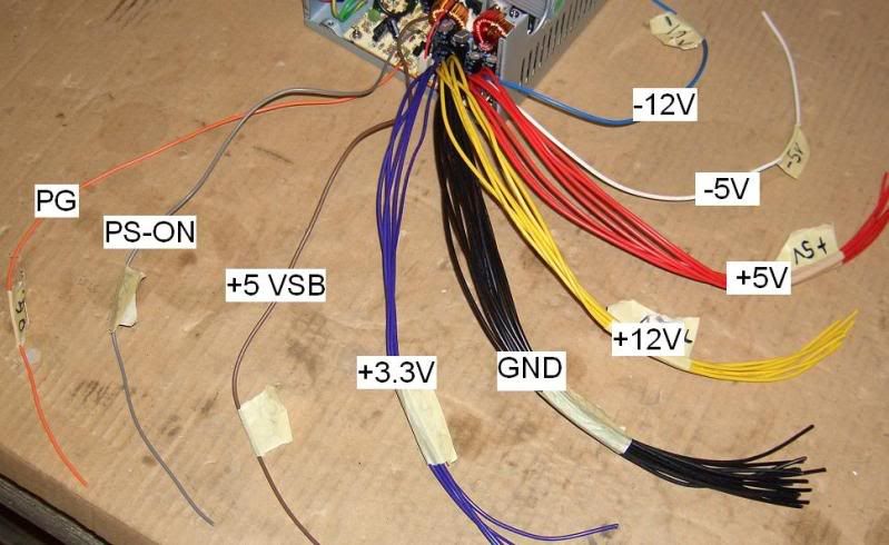
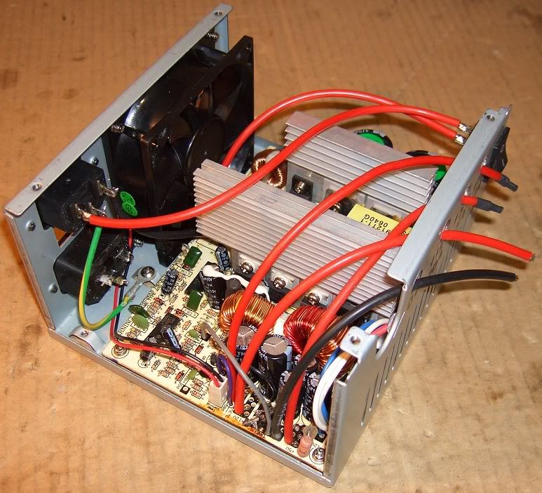
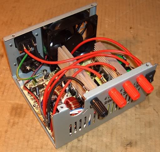
The next photo shows near completion, just waiting for my four binding posts to arrive. I have gone for Ground, +12V, +5V and +3.3V.
You will notice that I have stripped out all the wire bundles and replaced them with some nice, large gauge silicone wire. You will see that I have got rid of the Brown and Orange wires while I have connected the Grey wire to the Ground and the isolated Purple wire(not connected to other Purple 3.3V wires) to the 3.3V connection point.
I have also relocated the power switch to the opposite corner to make it more accessible and convenient.
Below shows what the wires were labelled as:
The next photo shows near completion, just waiting for my four binding posts to arrive. I have gone for Ground, +12V, +5V and +3.3V.
You will notice that I have stripped out all the wire bundles and replaced them with some nice, large gauge silicone wire. You will see that I have got rid of the Brown and Orange wires while I have connected the Grey wire to the Ground and the isolated Purple wire(not connected to other Purple 3.3V wires) to the 3.3V connection point.
I have also relocated the power switch to the opposite corner to make it more accessible and convenient.
 10-20-2009, 11:04 PM
#173
Senior Member
My Feedback: (12)

Join Date: Aug 2002
Location: Gaston,
SC
Posts: 576
Likes: 0
Received 0 Likes
on
0 Posts
I tried one and the fan runs. I put an automotive light socket with 1156 bulb on it....It turns on, fan is on, light is burning bright, BUT as soon as I hook up a charger, it all shuts down....I cant figure out what is going on....green wire to a black wire, grey wire to a red wire, 3 yellow wires for the +12 volts and three black for the negative..the light is on 1 red wire, +5 volts and a ground wire...Any ideas?
10-21-2009, 07:32 AM
#175
ORIGINAL: Andrew_S
<snip> .....BUT as soon as I hook up a charger, it all shuts down....I cant figure out what is going on.... grey wire to a red wire .......Any ideas?
<snip> .....BUT as soon as I hook up a charger, it all shuts down....I cant figure out what is going on.... grey wire to a red wire .......Any ideas?
Attach your charger before powering up the supply. Once stable, the PSU treats the charger as an internal short on the motherboard and powers off. These PSU's are designed to powerup with a heavy capacitive load, but not to remain on when a heavy load is connected.
andrew