


Advice needed in restoring a Dirty Birdi 40
 02-17-2017, 07:29 PM
#1

Thread Starter
My Feedback: (1)
Join Date: Sep 2010
Location: Grants Pass,
OR
Posts: 209
Likes: 0
Received 0 Likes
on
0 Posts
A couple years ago at a club Swap & Shop, I picked up for $10 a plane that that looked very interesting to me at the time. I didn't know what it was then, but now after much studying i am 99% sure it is an old kit built Dirty Birdi 40. The WS is 58" and it is 48 1/2" long to the front of the cowl. Other than some cracks around the canopy, everything else looks very structurally sound.
The original retracts are there. The ones on the wings do not operate very well, but the front retract can be operated fairly easy. The plane was originally covered with some type of fabric.
I would like to restore it back to original condition. I've never done retracts before, so I would like some recommendation for replacements. I know there are mechanical and electrical. Is there a weight advantage saving with electric, and also ease of installing? Hopefully the attached images show enough. Should the front retract be replaced, or could it be left alone if it seems to work ok?
All the control surfaces seem still solidly attached with pinned hinges. My concern is for recovering. The hinged control surfaces could be hard to recover.
I've covered several kits that I've built in the past with Sig Koveral and I prefer this and painting over plastic film. Does extra weight with this plane make a lot of difference? If so, than is plastic film the prerferred way to go?
I have a couple different OS engines I could use. One is an OS 46ax, and the other is an OS FS-52S. This plane had the engine side mounted. I would most want to use the FS 52 four stroke. Is there a preference here?
Please look at the attached photos. I'm open to recommendations. I'm sure I could come up with a restoration on my own, but any advice in helping to make this an easier and better project is much appreciated.
Thanks
Lamar
 02-19-2017, 10:20 AM
#2
My Feedback: (3)
Join Date: Apr 2008
Location: Montreal,
QC, CANADA
Posts: 5,200
Likes: 0
Received 5 Likes
on
5 Posts
Lamar,
You've correctly concluded that what you have is a DB40. If you prefer Koverall and paint, I don't see a problem with that just be diligent in the process up to the primer stage and spray the model with paint lightly. I'd recommend either lacquer or water borne colour paint as it's easier to control weight over paint such as epoxy. The lacquer won't be fuel proof but once you've trimmed out the model with colour and wet sanded it flat blending the paint lines together (easier with thin paint such as lacquer) and added any decals you desire, you will shoot the model with an acrylic urethane clear coat. I highly recommend SprayMax 2K if you don't have an HPLV gun.
As for power, I think you'll be a little disappointed with performance if you use a 4s 52. If you really want to use 4s, aim for a 63 to 80. An engine such as the YS 70 would be an excellent choice. On the other hand, if you want to keep it period correct, this is a classic pattern design meant to fly on 2s power and a tuned pipe. Such a setup with the 46AX would be perfect and my recommendation. I would also suggest an upright mount (actually at 20 deg CCW) which would put your header and pipe down the right side of the fuse above the wing. If you like the pipe slung under the wing, then the side mount is fine but it will require you to remove/install the pipe from the header each time you assemble or disassemble the model. That said, I would probably remove the glass cowl from the model and restore it or scrap it and build a new cowl from wood and blend it into the restoration priory to Koverall. I would likely scrap the glass cowl and go with the wood option as you need to do some wood work up front anyway. If the PET canopy is cracked or otherwise damaged, you can order a new one from Park Flyer Plastics who have made them from Bridi's original kit canopy. It will likely be easier to strip and fuse, sand it all down after a little TLC and recover prior to adding and fairing in the canopy before primer.
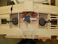
Retracts: what you have their are vintage Goldberg mechanicals. Most likely a good idea to scrap them or remove them and see if you can restore them (parts are hard to come by though), for another build once you see how cool retracts are. I would personally go with electric retracts on the mains (inexpensive units are available) and a Dave Brown (carried by Ohio Superstar) nose gear which is FW mounted like the Goldberg unit. The reason you want a mechanical NG is because the electrics don't fair too well on glow models. You can dedicate a mini servo to the NG and often it can be installed in the bay itself on its side although it looks like servo and pushrod are already installed in the wing bay unless the one servo in the wing was used to operate all three. With e-tracts in the wing, you can clean up the center section and install a pair of mini servos for the ailerons outboard of the main gear. Servos such as Tactic TSX25's are a solid choice. Likewise for the elevator of and rudder. You only need a smaller mini such as Spektrum A4000 or HiTec HS85 on the NG.
Due to the design of the offset Goldberg retracts, you're going to have to do a little surgery on the retract layout and mounts by cutting some new ones and reinstalling at the correct location in the wing ribs. You'll want to double up the ribs with 1/8" lite ply from the shear web (main spar location) back to under the TE sheeting. It's usually easier to use the actual rib to trace a template, cut the ribs in LP, mark them for a pair of 3/8" square hardwood rails and then cut the balsa ribs out using the LP ribs as template once they are glued in place. Then you can epoxy in your rails and install the retracts checking for proper function before resheeting the wing.
If you have other questions we're a true builders forum that's happy to help. However, the RCU branch has slowed down considerably due to issues in the past years and as a result most traffic on classic pattern has moved over to RCG. Hopefully, this forum will be great again one day.
I hope this helps,
David
PS Joe called them "Dirty Birdy's" and the 25 size version was a "Tweedy Bird". Not sure why he dropped the "y" on the little one.
You've correctly concluded that what you have is a DB40. If you prefer Koverall and paint, I don't see a problem with that just be diligent in the process up to the primer stage and spray the model with paint lightly. I'd recommend either lacquer or water borne colour paint as it's easier to control weight over paint such as epoxy. The lacquer won't be fuel proof but once you've trimmed out the model with colour and wet sanded it flat blending the paint lines together (easier with thin paint such as lacquer) and added any decals you desire, you will shoot the model with an acrylic urethane clear coat. I highly recommend SprayMax 2K if you don't have an HPLV gun.
As for power, I think you'll be a little disappointed with performance if you use a 4s 52. If you really want to use 4s, aim for a 63 to 80. An engine such as the YS 70 would be an excellent choice. On the other hand, if you want to keep it period correct, this is a classic pattern design meant to fly on 2s power and a tuned pipe. Such a setup with the 46AX would be perfect and my recommendation. I would also suggest an upright mount (actually at 20 deg CCW) which would put your header and pipe down the right side of the fuse above the wing. If you like the pipe slung under the wing, then the side mount is fine but it will require you to remove/install the pipe from the header each time you assemble or disassemble the model. That said, I would probably remove the glass cowl from the model and restore it or scrap it and build a new cowl from wood and blend it into the restoration priory to Koverall. I would likely scrap the glass cowl and go with the wood option as you need to do some wood work up front anyway. If the PET canopy is cracked or otherwise damaged, you can order a new one from Park Flyer Plastics who have made them from Bridi's original kit canopy. It will likely be easier to strip and fuse, sand it all down after a little TLC and recover prior to adding and fairing in the canopy before primer.
Retracts: what you have their are vintage Goldberg mechanicals. Most likely a good idea to scrap them or remove them and see if you can restore them (parts are hard to come by though), for another build once you see how cool retracts are. I would personally go with electric retracts on the mains (inexpensive units are available) and a Dave Brown (carried by Ohio Superstar) nose gear which is FW mounted like the Goldberg unit. The reason you want a mechanical NG is because the electrics don't fair too well on glow models. You can dedicate a mini servo to the NG and often it can be installed in the bay itself on its side although it looks like servo and pushrod are already installed in the wing bay unless the one servo in the wing was used to operate all three. With e-tracts in the wing, you can clean up the center section and install a pair of mini servos for the ailerons outboard of the main gear. Servos such as Tactic TSX25's are a solid choice. Likewise for the elevator of and rudder. You only need a smaller mini such as Spektrum A4000 or HiTec HS85 on the NG.
Due to the design of the offset Goldberg retracts, you're going to have to do a little surgery on the retract layout and mounts by cutting some new ones and reinstalling at the correct location in the wing ribs. You'll want to double up the ribs with 1/8" lite ply from the shear web (main spar location) back to under the TE sheeting. It's usually easier to use the actual rib to trace a template, cut the ribs in LP, mark them for a pair of 3/8" square hardwood rails and then cut the balsa ribs out using the LP ribs as template once they are glued in place. Then you can epoxy in your rails and install the retracts checking for proper function before resheeting the wing.
If you have other questions we're a true builders forum that's happy to help. However, the RCU branch has slowed down considerably due to issues in the past years and as a result most traffic on classic pattern has moved over to RCG. Hopefully, this forum will be great again one day.
I hope this helps,
David
PS Joe called them "Dirty Birdy's" and the 25 size version was a "Tweedy Bird". Not sure why he dropped the "y" on the little one.
Last edited by doxilia; 02-19-2017 at 10:22 AM.
02-19-2017, 10:35 AM
#3
My Feedback: (3)
Join Date: Apr 2008
Location: Montreal,
QC, CANADA
Posts: 5,200
Likes: 0
Received 5 Likes
on
5 Posts
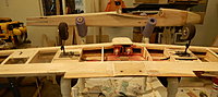
I've attached a couple of snaps showing my DB40 wing e-tract mount (model built from a CAD laser kit I offer). Note that I used 1/16" birch ply rib doublers instead of lite ply but I also brace the rails from rib to rib between the top and bottom sheeting. Once it's all epoxied together, it is pretty solid. Of course, this is another option.
The large bent washers are just there to pull in the 4-40 blind nuts into the rails. I use 4-40 nylon bolts to secure the retracts in place.
David
The large bent washers are just there to pull in the 4-40 blind nuts into the rails. I use 4-40 nylon bolts to secure the retracts in place.
David
Last edited by doxilia; 02-19-2017 at 10:38 AM.
02-19-2017, 04:33 PM
#4

My Feedback: (12)
Having just restored an MK Aurora, here's my advice regarding the retracts..... keep what you have and spend the time cleaning and lubricating them. They should be fairly easy to disassemble and a bit of abrasive will go a long way. Take them apart and use either softscrub or rubbing compound to resurface the areas where the metal rotates against the plastic. Then use some lithium grease. The springs should be easy to find and replace as well. I looked at installing pneumatics on the Aurora but opted to stay with what I had. Mostly because I didn't want to reengineer the wings, which is what you may have to do if you go electric or pneumatic. Also, don't put electrics on this plane, they aren't as fool proof as one would think. Here's a link to some hobbico retracts which may fit.. http://www3.towerhobbies.com/cgi-bin...Fd2PswodBTQHag Upgrading retracts is a pain. The mechanical ones work just fine and with a programmable radio you get the travel you need with a cheap analog servo. Hope this helps.
Ken
Ken
02-19-2017, 06:26 PM
#5
Thread Starter
My Feedback: (1)
Join Date: Sep 2010
Location: Grants Pass,
OR
Posts: 209
Likes: 0
Received 0 Likes
on
0 Posts
Thanks David and Ken for the replies back and good advice.
I have an OS 55 ax that is on another plane that I could use on the DB. It is a real strong running engine.. It has a Macs muffler installed on it now. This engine should provide me with a little more power than the 46 ax. As far as mounting the engine, the DB cowl is already set up for a side mount and I think it would make things much simpler to just keep it this way. I set an extra engine I have, on the engine mount and it seems to fit good this way.
The original canopy doesn't have any damage. It is just coming unattached from the fuselage and can easily be epoxied back and have the cracks filled.
I believe that only one servo operated all the retracts. David, you mentioned buying a Dave Brown mechanical retract for the nose. The present retract that is there now, seems to operate fine pulling and pushing the control linkage. I don't think it would be any problem mounting a servo at the present location to make it work. If I purchase new electric retracts for the main LG, can I use the same wheel wells there now, and work back from there to build new mounts? As far as Ken mentioning to keep the original, I'll take a good look at them when I remove them to see if I can get them to operate better. If I did decide to reuse the, I'm going to need a little help on how to attach the linkage to one servo. Does a standard servo work for this or do I need a high torque?
The original torque ailerons system is still intact. Is it a preferable to just cut that all out and install the dual mini servos? I think I may want to cut out all the hinges for ailerons,rudder and elevator anyway for ease of refinishing.
This restoration will most likely be slow, especially since flying season is coming. I'm sure I'll have more questions as I go. I'm attaching a few more photos. One of the photos shows a post inside the wing that protrudes on the outside. Does this have a purpose?
Thanks again
Lamar
02-19-2017, 10:39 PM
#6
My Feedback: (3)
Join Date: Apr 2008
Location: Montreal,
QC, CANADA
Posts: 5,200
Likes: 0
Received 5 Likes
on
5 Posts
The wing post was most likely a tuned pipe mount point. A bracket is normally attached to the hard point and the pipe held by the bracket.
Further thoughts when I can get to a proper keyboard.
David
Further thoughts when I can get to a proper keyboard.
David
02-20-2017, 09:53 AM
#7
My Feedback: (3)
Join Date: Apr 2008
Location: Montreal,
QC, CANADA
Posts: 5,200
Likes: 0
Received 5 Likes
on
5 Posts
Thanks David and Ken for the replies back and good advice.
I have an OS 55 ax that is on another plane that I could use on the DB. It is a real strong running engine.. It has a Macs muffler installed on it now. This engine should provide me with a little more power than the 46 ax. As far as mounting the engine, the DB cowl is already set up for a side mount and I think it would make things much simpler to just keep it this way. I set an extra engine I have, on the engine mount and it seems to fit good this way.
I have an OS 55 ax that is on another plane that I could use on the DB. It is a real strong running engine.. It has a Macs muffler installed on it now. This engine should provide me with a little more power than the 46 ax. As far as mounting the engine, the DB cowl is already set up for a side mount and I think it would make things much simpler to just keep it this way. I set an extra engine I have, on the engine mount and it seems to fit good this way.
Yes, the 55AX would be an excellent choice. Of the three engines, that's what I would use. As for the side mount, that's something I wouldn't worry about much since you're going to have to give your FW and cowl some TLC to get them back in shape. If you prefer the side mount, stick with it. The advantage is that it positions the muffler with the exhaust pointing downwards so if you are going the run the 55 with a muffler, go side mounted. If you plan to pipe it, I would rotate to vertical (or 20 deg CCW) for an easier and faster model to assemble and disassemble at the field. The pipe would put the exhaust past and over the wing which can also be directed downwards with a silicone deflector. That said, I would strip all paint and covering from the model and take a good look at the integrity of the FW and engine mount before proceeding with engine mounting. One more advantage of the side mount is that it puts the carb line closer to the tank center line on Bridi designs such as the DB.
The original canopy doesn't have any damage. It is just coming unattached from the fuselage and can easily be epoxied back and have the cracks filled.
I believe that only one servo operated all the retracts.
David, you mentioned buying a Dave Brown mechanical retract for the nose. The present retract that is there now, seems to operate fine pulling and pushing the control linkage. I don't think it would be any problem mounting a servo at the present location to make it work.
If I purchase new electric retracts for the main LG, can I use the same wheel wells there now, and work back from there to build new mounts?
As far as Ken mentioning to keep the original, I'll take a good look at them when I remove them to see if I can get them to operate better. If I did decide to reuse them, I'm going to need a little help on how to attach the linkage to one servo. Does a standard servo work for this or do I need a high torque?
http://www.spektrumrc.com/Products/D...odID=SPMSA7040
Another option for the mechanical mains is to use dual mini servos essentially converting the mechanicals into e-tracts of sorts. The photo below shows how this is often done on scale models. The dual mini's and shorter linkages are equivalent in weight to the longer linkages and single retract servo in the middle. Each system has its pros and cons but I won't get into that.
The original torque ailerons system is still intact. Is it a preferable to just cut that all out and install the dual mini servos? I think I may want to cut out all the hinges for ailerons, rudder and elevator anyway for ease of refinishing.
David
02-20-2017, 08:17 PM
#8
Thread Starter
My Feedback: (1)
Join Date: Sep 2010
Location: Grants Pass,
OR
Posts: 209
Likes: 0
Received 0 Likes
on
0 Posts
David, thanks for the very detailed reply. I really like the idea of not having a hatch on the bottom of the wing for a retract servo. The single servo per retract like the photo you attached is the most appealing to me. Looking at my previous posted photo of the front retract, do you think there will be plenty of room for a servo there? I looked at the Hobbico retract set that Ken mentioned, and they do look like the mechanical part will be more compact and take up less space.
I'll go with one servo per aileron on the wing. I've always done them that way on my kit builds. Easy to do, and the Tactic TSX25's sound real good. High torque and digital at a reasonable price. Are those the ones you would use for the single servo retracts? How much torque do I need for the retracts?
I removed the retracts today, and I wouldn't want to reuse the mains. The nose retract seems to work fine, but I am concerned about room for a servo mounting in that space to operate the retract.
As I remove parts from this plane, I'm starting to get real motivated in doing the restore. This plane is really built solid. Comparing it to the ARF's we get today where you have to be very careful as to where and how you pick them up for fear of breaking something the DB is built like a tank.
Lamar
02-21-2017, 08:28 PM
#9
Thread Starter
My Feedback: (1)
Join Date: Sep 2010
Location: Grants Pass,
OR
Posts: 209
Likes: 0
Received 0 Likes
on
0 Posts
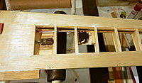
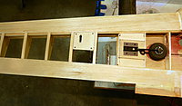
I've been reading over again all the advice that David gave me, then going back to look at the DB to help put everything together in my mind. The first thing I've been trying to figure out is the best way to do a mechanical nose gear retract. I looked at some pictures of the Hobbico nose gear retract, and from what I can tell, this retract needs to be mounted on a horizontal plane to the fuselage. I don't think this is possible on this DB, because the fuel tank is right there. I think I need to stick with the original nose gear retract which is mounted vertically to the FW. I've had doubts that I could fit a mini servo in the retract compartment, but I got to thinking that could run the retract linkage back in the fuselage and put a mini servo close to where the other servos will be located. See attachment.
My thought has then been going to the main retracts in the wing. David first said he would personally go with electric retracts to clean up the unsightly bottom of the wing. this seems to be the easiest option. Do you feel David that the electrics will work as well as the mechanical? I want to install ones that have the least chance of problems later.
In a earlier post I said that all three retracts were operated by one servo. I thought that the hatch on the bottom of the wing was to access the servo, and I placed a servo there thinking that was how it mounted. As I look at the top of the wing now, it looks like the servo mounted on top. I think the only reason the hatch is there on the bottom is so the nose gear servo linkage could be disconnected for removal of the wing. Maybe that would be still the best way to operate the main retracts. I can still get rid of that ugly hatch on the bottom. let me know what you think.
I started stripping the cover fabric off the fuselage today. The canopy came up with the fabric, because it was glued on after the fabric covering was installed. I believe I can salvage it. One other thing that also came off with me pulling off the fabric covering was the ventral fin. It was apparently glued on also after the fabric was covered on the fuselage. That seemed a little odd to me.
Lamar
02-22-2017, 07:32 AM
#10
My Feedback: (3)
Join Date: Apr 2008
Location: Montreal,
QC, CANADA
Posts: 5,200
Likes: 0
Received 5 Likes
on
5 Posts
I've been reading over again all the advice that David gave me, then going back to look at the DB to help put everything together in my mind. The first thing I've been trying to figure out is the best way to do a mechanical nose gear retract. I looked at some pictures of the Hobbico nose gear retract, and from what I can tell, this retract needs to be mounted on a horizontal plane to the fuselage. I don't think this is possible on this DB, because the fuel tank is right there.
If you are able to keep the Goldberg NG then this is moot but if you need a new retract you can install a belly/pan mount retract by first installing a 1/16" ply plate separating the tank bay from the gear bay. If you brace the sides with 1/4 or 3/8" tristock and epoxy everything in place, it should provide a good base for a 3/16" ply NG only plate glued to the FW, tank plate and sides, again with bracing on the sides. You will notice the Hobbico NG is quite shallow so this makes things a little easier.
I've set my DB40 up using a belly mount NG and just used a 1/4" ply horizontal former keyed into the FW and side doublers so it can be done space wise. I'm using a Sullivan 10 oz round tank which is supported around the cap by a 1/16" ply partial former between the end of the NG plate, side doublers and the fuse top blocks.
I think I need to stick with the original nose gear retract which is mounted vertically to the FW. I've had doubts that I could fit a mini servo in the retract compartment, but I got to thinking that could run the retract linkage back in the fuselage and put a mini servo close to where the other servos will be located. See attachment.
My thought has then been going to the main retracts in the wing. David first said he would personally go with electric retracts to clean up the unsightly bottom of the wing. this seems to be the easiest option. Do you feel David that the electrics will work as well as the mechanical? I want to install ones that have the least chance of problems later.
In a earlier post I said that all three retracts were operated by one servo. I thought that the hatch on the bottom of the wing was to access the servo, and I placed a servo there thinking that was how it mounted. As I look at the top of the wing now, it looks like the servo mounted on top. I think the only reason the hatch is there on the bottom is so the nose gear servo linkage could be disconnected for removal of the wing. Maybe that would be still the best way to operate the main retracts. I can still get rid of that ugly hatch on the bottom. let me know what you think.
I started stripping the cover fabric off the fuselage today. The canopy came up with the fabric, because it was glued on after the fabric covering was installed. I believe I can salvage it. One other thing that also came off with me pulling off the fabric covering was the ventral fin. It was apparently glued on also after the fabric was covered on the fuselage. That seemed a little odd
David
Last edited by doxilia; 02-22-2017 at 07:41 AM.
02-22-2017, 10:58 AM
#11
Thread Starter
My Feedback: (1)
Join Date: Sep 2010
Location: Grants Pass,
OR
Posts: 209
Likes: 0
Received 0 Likes
on
0 Posts
David, you mentioned that you use a Sullivan round 10 oz. tank. The tank that came with this DB is flat on bottom and a very tight fit. Do you think the Sullivan tank will be an easier fit? The bottom of the body cavity (top really) is very thick balsa, and I'm sure it could be scraped down a little without weakening the structure.
The Hobbico 3 pack set of mechanical retracts is not that expensive. I think I'll order that set, then I'll be able to see if room is available to fit the base mount nose retract.
The Great Planes DB 60 ARF instruction manual has a section on installing Hobbico mechanical retracts that looks very informative.
I have extra standard analog servos. Will these be ok to use for my main retracts and nose gear retracts?
I don't think this original old DB was built very light. Does this plane benefit by keeping it as light as possible during my restoration. It seems that most planes do, but the reason I ask is because I read the Ultra Sport 60 build thread by the late Minnflyer, and he stated that the Ultra Sport flies better with more weight.
After looking at the photos of this DB that I've posted, do you have any idea how old it may be? Possibly 70's vintage?
Lamar
02-22-2017, 12:04 PM
#12
My Feedback: (3)
Join Date: Apr 2008
Location: Montreal,
QC, CANADA
Posts: 5,200
Likes: 0
Received 5 Likes
on
5 Posts
David, you mentioned that you use a Sullivan round 10 oz. tank. The tank that came with this DB is flat on bottom and a very tight fit. Do you think the Sullivan tank will be an easier fit? The bottom of the body cavity (top really) is very thick balsa, and I'm sure it could be scraped down a little without weakening the structure.
Bridi designed some nice planes but they weren't especially light or "conceptually clever". One such example is how the front top curvature in the tank bay area was dealt with. Basically in order to achieve top roundness, the tank bay was spanned with a slab of 3/8" balsa followed by the 1/4" (or was it 3/8" in the original - can't recall) top sheet. This results in the center portion in the tank bay being 5/8" or perhaps 3/5" thick! So yes, you can hollow out this area which will also allow you raise the tank level putting it more inline with the carb height in an upright engine installation. In my redesign, I kept much of the original structure the same in the interest of honouring Bridi but I took the liberty to drop fuse side thickness (1/8" down from 3/16") as well as doubler weight and remove unneeded wood. The front tank block is an example where I cut out much of the middle leaving only the front and sides present where wood is needed. The Sullivan 10 oz tank fits with no problems as I suspect most other shallow draft 10 oz tanks would. With a little effort, one could probably get a Hayes 12 oz low profile in as well but they are unfortunately discontinued. Whatever you do, I strongly recommend you use new accessories. Not worth the hassle to do all the work and have 20-40 year old parts fail on you - especially the tank.
The Hobbico 3 pack set of mechanical retracts is not that expensive. I think I'll order that set, then I'll be able to see if room is available to fit the base mount nose retract.
The Great Planes DB 60 ARF instruction manual has a section on installing Hobbico mechanical retracts that looks very informative.
The Great Planes DB 60 ARF instruction manual has a section on installing Hobbico mechanical retracts that looks very informative.
I have extra standard analog servos. Will these be ok to use for my main retracts and nose gear retracts?
I don't think this original old DB was built very light. Does this plane benefit by keeping it as light as possible during my restoration. It seems that most planes do, but the reason I ask is because I read the Ultra Sport 60 build thread by the late Minnflyer, and he stated that the Ultra Sport flies better with more weight.
After looking at the photos of this DB that I've posted, do you have any idea how old it may be? Possibly 70's vintage?
Lamar
Lamar
David
PS I wouldn't install the NG servo back where you drew it on the photo. Use that area for tail servos and receiver. Install the NG and throttle servos further up just aft of where the battery is needed for balance - probably behind the fuel tank with the 55AX.
Last edited by doxilia; 02-22-2017 at 12:09 PM.
02-22-2017, 06:01 PM
#13
I made at least seven or eight of these planes back in its hay day. All had retracts operated by one servo. Servos were very expensive back then $40 or so and that was a lot back then. I had one set of Goldberg retracts that I had trouble making loose enough. Then I had a couple sets of Dave Brown. These worked great. I was in tool and die school and apprentice then so I made my own replacement parts. The last set was Rohm Air. These used Freon 12. They worked very well as you could put liquid freon in the smal tank and it would last all day.
my first one had just a K&B 40 with tuned pipe. It was ok but....I also worked in a hotrod shop and had access to nitro, alcohol and any kind of oil I wanted. I blew a rod out the side of the block rather spectacularly so I went to K&B 6.5 RE with tuned pipe through the canopy. These motors really screamed with pumps and tuned pipes. The last two had K&B 7.5 ducted fan motors with pumps and tuned pipes. I was really heavy into high nitro stuff by then. Often burning a plug a flight. I used to buy a couple cards of plugs at a time. This combination produced some really high speeds. The cops could only lock on up to around 120 or so and these planes hit this without a dive. In the day these were way faster than the quickly 500 planes.
As as you get to the bigger than .45 motors you will be restricted in prop size. You can only make the gear so long and use only so big of tires. Ten inches was all,I ever used. I cut 11 inch ones down. Multi blade props didn't exist back then. I used very small wheels as we had a paved runway.
Id use two aileron servos and somebody makes a knock off of David Brown retracts if you can't get originals. I'd mount the nose gear servo inverted in the wing with a hatch covering it. Just have a hole in the leading edge and poke the NG wire through to the servo. Either leave the arm on the wire or servo which ever is easiest.
hollow out what you can, keep it straight. Make sure you have the full wing filet...its for aerodynamics. Seal all control surfaces.
02-23-2017, 01:13 PM
#14
My Feedback: (3)
Join Date: Apr 2008
Location: Montreal,
QC, CANADA
Posts: 5,200
Likes: 0
Received 5 Likes
on
5 Posts
Lamar,
I thought the pictures below might be of some help in your refurbish.
The first one shows how I redesigned the front top tank area from the inside. The "bottom" sheet that you see is actually a 1/4" balsa top sheet and the only piece that spans the width of the fuse on top. In order to produce a nice rounded exterior top along the lines of the glass DB60 fuse, I used a mix of 3/8" tristock in the canopy/wing bay area where less curvature is required as the canopy is essentially blended to the corners of the fuse and switched to 1/2" tristock aft of the wing TE where the tail boom can be made rounder. You'll also see in the picture that the 3/8" balsa tank top block (allowing the fuse top to be "blended down" on top), which replaces the tristock forward of F2, has a U-shaped cutout where it mates to the F2 former. All the wood in the middle is unnecessary since only the front and sides are contoured into the engine bay and spinner. This cutout (which you can carve out) is what allows me to locate a Sullivan 10 oz round tank which as you can see is supported in the rear by the cutout in the F2 former. Split fuel tubing or foam tape will be added around the opening to dampen vibration. The front, as mentioned previously, is supported by a 1/16" "intermediate" former which is epoxied to the rear of the flat NG retract plate (third picture) and the fuse sides and top block. It has a circular cutout which supports the tank around the cap neck. The cutout in the top block provides 3/8" of clearance and an opening to prevent any fuel from potentially being trapped between the former, FW and NG plate in the event of a leak from the cap. Before gluing all the parts together, the area is all fuel proofed with laminating epoxy.
The second picture shows my simple servo tray for two mini servos (elevator and rudder) and a micro throttle servo. The area in the front center is where I plan to locate a small 6 channel (elevator, rudder, 2 x aileron, throttle and retracts) receiver on double sided foam tape. The LiFe battery, voltage regulator and switch will be located in front of the tray on a small lite ply tray which I can also remove via screws in the event I need to service the fuel tank. It will also be somewhat accessible from the retract bay with the gear extended once I make the cutout for the NG in the bottom FWIW, note that I used 1/16" x-grain balsa as doublers in the wing bay. I thnkt he original plans might show this as well. In a revision to the kit I will likely switch to a single piece 1/32" ply doubler as I have 1/16" ply in the tank bay and 1/16" balsa in the radio/wing bay. The single piece 1/32" will prevent stress risers which occur at the F2 and F3 formers as a result of the doubler discontinuity. The F2 location being of particular importance as the fuse contours down to meet the narrower F1 FW and nose ring.
The third picture shows a flat mount NG e-tract for which I still have to manufacture a steering mechanism. Note that I underestimated the length of the e-tract mount base in the re-design prototype (corrected in the production kits) so I had to extend the 1/8" ply mount plate to allow the rear screws to be installed. The two plates are epoxied together and there is a 1/8" ply doubler on the underside (actually top side) to capture the blind nuts and strengthen the assembly. The sides are braced with 3/8" tristock as well. The two tabs on the front key into the FW "back" which is constructed from a 2-ply laminate of 1/8" ply just like the NG plate. I'm going to test this inexpensive (~$10 a unit if memory serves) "electric trio" setup with YS 45FS power and see how it holds up. If it's giving me problems, I can switch the NG to a flat mechanical unit (e.g., Hobbico) and install a mini or sailplane "thin wing" type servo (e.g., Spektrum A7050) in the NG bay for retraction.
The last several pics show two FW mount type mechanical NG retracts. The black mount larger unit is the Dave Brown suggested in earlier posts. This unit is all metal construction and has been manufactured for 30+ years and is very reliable. IMO it is better suited to 60 size models as it is on the larger side as can be seen when compared to the smaller anodized gold Japanese MK unit to the right. The MK units are lighter and also dependable but they do have some plastic parts and unfortunately are discontinued. Still, they are occasionally available on the auction sites for sale and the smaller size and lighter weight make them ideal for 45 size models. There are also slightly smaller SS type units for 30 size pattern classics which MK designed many of and kitted. Fantastic little bullets! I will be releasing a Japanese design 30 size MK kit called the Cosmos later this year (see final attachment).
I hope these pics and description are of some use in your refurbish. Looking forward to seeing some more stripped down pictures and some freshly sanded balsa!
Cheers, David.
P.S. If you double click the pictures (i.e., click on the expanded picture window), they will load into a separate browser window properly oriented. Not sure why RCU rotates them now - a new "feature". Probably just so they align better in the post window.
Last edited by doxilia; 02-23-2017 at 01:15 PM.
02-25-2017, 12:08 PM
#15
Thread Starter
My Feedback: (1)
Join Date: Sep 2010
Location: Grants Pass,
OR
Posts: 209
Likes: 0
Received 0 Likes
on
0 Posts
Thanks again David for your very detailed info., and also bentwings for for your post.
I've been spending some time stripping off the old covering. It takes a little more time around the tail feathers to keep from damaging anything. All I have left now is the rudder, elevator and ailerons, which are still attached with hinges. The hinges are all pinned and they are double pegged with toothpicks. I'm thinking of trying to push or drill out the pegs, then see if the hinges can be pulled out.
I like the picture of the servo tray you attached in your last post. The rear of this DB body cavity looks to have a couple perpendicular blocks already installed for a previous servo tray. Should be an easy process to make one to fit there. I'm thinking of a tray for 4 mini servos, which would include rudder, elevator, throttle and nose gear retract. I don't think you gave me a specific answer David, unless I missed it, but I was thinking of putting the nose gear retract servo back in the body across from the throttle servo location. This would only mean extending the length of the retract rod length a couple inches from original. The rudder servo would be behind the retract servo in the same line and the elevator servo across from the rudder servo. Do you see any problems doing this?
My original fuel tank measured 6 1/2" L X 2 3/8" W X 2 1/16" H. The Sullivan 10 oz round is 4 7/8" X 2 5/16" Dia. This should fit fine. I will scrape a radius in the compartment some for clearance. It is a very rough hacked out surface there now.
I've got a list of items I want to order from Tower Hobbies soon. I'd like to get a recommendation from you David on a few items first before I make the order. The first thing are the wheels. This plane had Du-bro 2 1/4' mains and 2' nose gear rubber wheels. I can save a couple ounces weight by going with lite wheels. There are several to select from. Du-Bro Treaded Lightweight, Du-Bro Super Lite wheels and Dave Brown lite wheels. Any preference there?
The other thing is the servos. I think I'll go with all mini servos, for weight saving and compactness. I'm looking at seven new servos. you mentioned Tactic TSX25's. That would be a cost of near $140 for the servos. I was looking at another servo, RC Gear Shop mini digital metal gear dual BB from Tower at half the price that may be good for some of the applications and could save me a little $$. They have lower torque, but they are still near a Futaba S3004 torque. Could you let me know what would work and where.
David, I have some DB 40 drawings I downloaded a few years ago, and I was just re looking at them the other day, and I looked down at the specs block on the bottom and it says Cad design David Oxilia. I now realize I am getting expert advice on the DB. I really do appreciate your help. I do want to give the restoration of this old DB some justice. I'm now putting a future build of a great Planes Ultra Sport on the back burner after this restoration.
Lamar
02-28-2017, 11:34 AM
#16
My Feedback: (3)
Join Date: Apr 2008
Location: Montreal,
QC, CANADA
Posts: 5,200
Likes: 0
Received 5 Likes
on
5 Posts
I like the picture of the servo tray you attached in your last post. The rear of this DB body cavity looks to have a couple perpendicular blocks already installed for a previous servo tray. Should be an easy process to make one to fit there. I'm thinking of a tray for 4 mini servos, which would include rudder, elevator, throttle and nose gear retract. I don't think you gave me a specific answer David, unless I missed it, but I was thinking of putting the nose gear retract servo back in the body across from the throttle servo location. This would only mean extending the length of the retract rod length a couple inches from original. The rudder servo would be behind the retract servo in the same line and the elevator servo across from the rudder servo. Do you see any problems doing this?
you can install the servos however you find most convenient. The position is best decided based on how the linkages are routed. My preference for rudder is a light pull-pull setup so that's why one of the servos on my tray is centered. For the elevator I like to have independent adjustment on each surface so I either use two servos (mixed in radio) like I do on ailerons or I use a forked (or joined) pushrod to a single servo as I did on this model and tray. The servo is offset in order to center the forked pushrod on the fuse to avoid differential movement on the surfaces. In other words, there are many ways to go about it.
For the NG I like to keep the linkages short and out of the way of the rest of the radio so I avoid traversing the receiver and battery if possible. As I mentioned in a post or two back, a mini servo (e.g. HiTec HS82 or 85 or Spektrum A4010) or a thin wing servo can be flat or side mounted in the NG bay which keeps the linkage direct (no bends or kinks) and about 3" long or so. For steering, I like to use another mini servo as decoupling the steering from the rudder allows the NG to not be actuated when retracted. This also avoids possible binding which is often a cause of retract failure to deploy. Basically one sets up a rudder/steering/retract mix so that the steering only functions when the retracts are deployed.
That said, your proposed layout should work but you may experience some linkage issues with the NG as proposed. Just a matter of spending a little time getting it right.
My original fuel tank measured 6 1/2" L X 2 3/8" W X 2 1/16" H. The Sullivan 10 oz round is 4 7/8" X 2 5/16" Dia. This should fit fine. I will scrape a radius in the compartment some for clearance. It is a very rough hacked out surface there now.
I've got a list of items I want to order from Tower Hobbies soon. I'd like to get a recommendation from you David on a few items first before I make the order. The first thing are the wheels. This plane had Du-bro 2 1/4' mains and 2' nose gear rubber wheels. I can save a couple ounces weight by going with lite wheels. There are several to select from. Du-Bro Treaded Lightweight, Du-Bro Super Lite wheels and Dave Brown lite wheels. Any preference there?
The other thing is the servos. I think I'll go with all mini servos, for weight saving and compactness. I'm looking at seven new servos. you mentioned Tactic TSX25's. That would be a cost of near $140 for the servos. I was looking at another servo, RC Gear Shop mini digital metal gear dual BB from Tower at half the price that may be good for some of the applications and could save me a little $$. They have lower torque, but they are still near a Futaba S3004 torque. Could you let me know what would work and where.
David, I have some DB 40 drawings I downloaded a few years ago, and I was just re looking at them the other day, and I looked down at the specs block on the bottom and it says Cad design David Oxilia. I now realize I am getting expert advice on the DB. I really do appreciate your help. I do want to give the restoration of this old DB some justice. I'm now putting a future build of a great Planes Ultra Sport on the back burner after this restoration.
Glad to be of help and build on! The stripping is coming along nicely. Make sure you sand up some fresh grain and go as round as possible on that fuse top. They look so much better when tear dropped than as boxy fuses.
David
Last edited by doxilia; 02-28-2017 at 11:39 AM.
03-03-2017, 10:47 AM
#17
Thread Starter
My Feedback: (1)
Join Date: Sep 2010
Location: Grants Pass,
OR
Posts: 209
Likes: 0
Received 0 Likes
on
0 Posts
Want to give an update on my restoration progress. I have all the old covering removed from the control surfaces. I had to be careful getting it off, but I think the stab and elevators came out fine, the ailerons were a special chore because of the torque rods, but they should be fine to use again. I used my Dremel tool to cut the torque rods out. I will just need to fill in the gap from the torque rods with putty. The fin, rudder and ventral fin didn't come out so well. I plan on making new ones, using the originals for patterns. One thought I have is since I'm making new ones, is there any benefit in adding a little more rudder width? Possibly helping to improve stall turns or knife edge flying.
I did a little sanding on the body and cowl. They blend together fairly well. I'll need a little putty fill, but not much. I may try adding a little glass and resin in a couple areas on the cowl edges to clean it up better. First I'll wait until I do a pre mount of my OS 55 engine to see where I may need to cut to fit.
I marked the canopy location with pencil for a guide to do a little more rounding of the body as David suggested. This plane is built so beefy, that I'm sure a little more balsa removal won't hurt. It will even remove some more weight. That leads me to another question. It seems there are more areas I could go during this restoration to remove some weight. The area under the canopy could be cut out, leaving enough room for reattaching the canopy. As I go to make a new fin, I could do a framed up version, saving some balsa weight, add some extra holes in the stab and rudder to also remove some balsa weight. These areas will all be covered with Koverall, which adds significant strength. I've done this before with a 4 Star 120 build. I'd like an opinion on this idea.
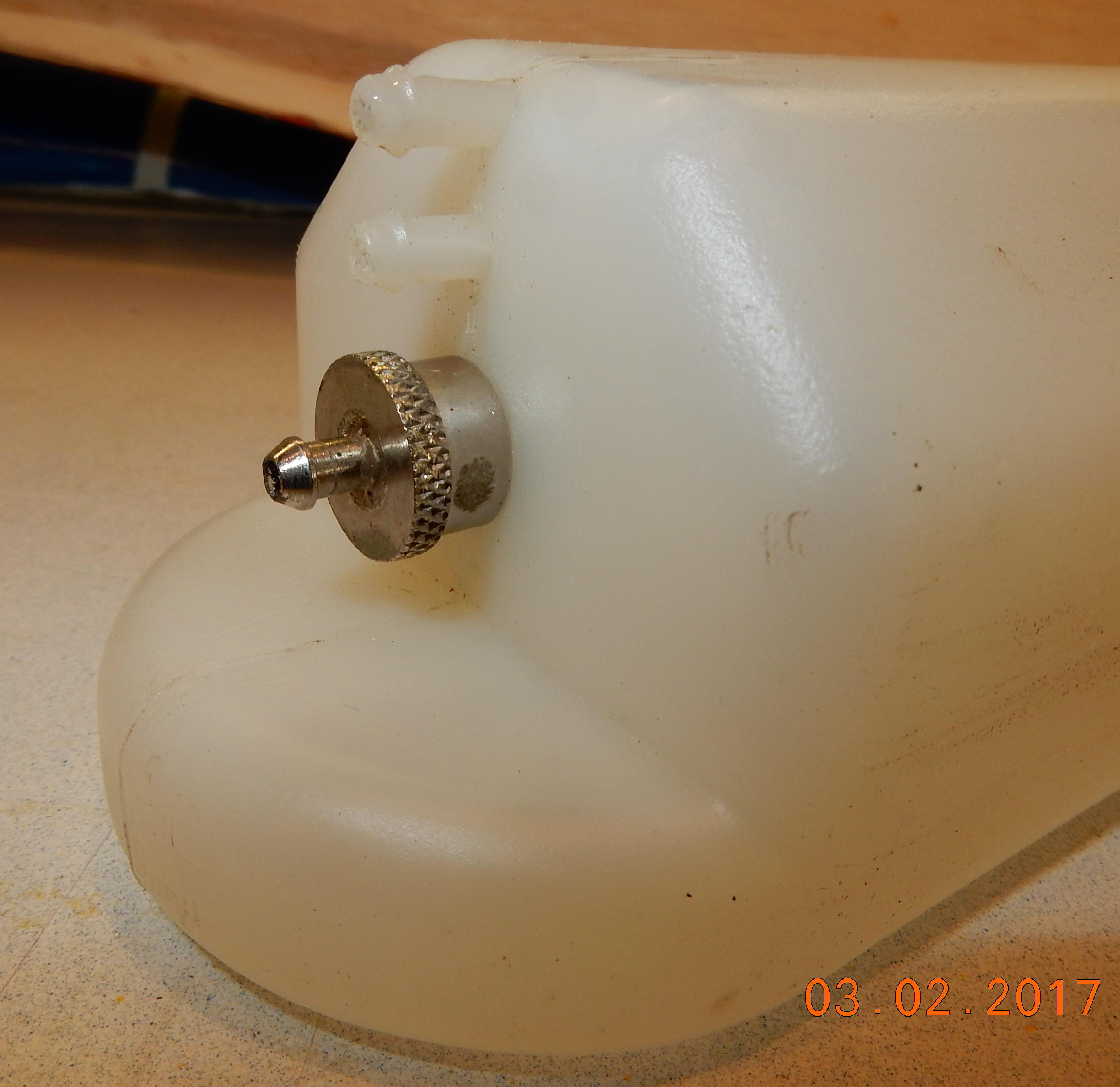
David's last post mentioned that the original tank I had was a good one, and I may just do a clean up and change fuel lines. I did do the clean up with denatured alcohol and pulled the stopper. This tank is different than any I have seen before, so I've attached photos of the removed stopper, and would like some a little explanation of it's setup. The stopper is not rubber like I've seen before. It is all metal with just a very snug fit into the tank. I thought the gnarled part of the stopper could be turned to loosen it, but as it turns out it just needs to be twisted and pulled to remove. The stopper still goes back in place with a tight fit. The two fuel fittings above the stopper I assume are the vent and fuel fill. They both just go to the tank with no lines after entry. Which is the vent, and which is the fill?
I've got my Hobbico retracts, axels, DuBro lite wheels and one mini servo on order. Only ordered one servo for now to check it out, and see if it will work for different applications.
Lamar


I did a little sanding on the body and cowl. They blend together fairly well. I'll need a little putty fill, but not much. I may try adding a little glass and resin in a couple areas on the cowl edges to clean it up better. First I'll wait until I do a pre mount of my OS 55 engine to see where I may need to cut to fit.
I marked the canopy location with pencil for a guide to do a little more rounding of the body as David suggested. This plane is built so beefy, that I'm sure a little more balsa removal won't hurt. It will even remove some more weight. That leads me to another question. It seems there are more areas I could go during this restoration to remove some weight. The area under the canopy could be cut out, leaving enough room for reattaching the canopy. As I go to make a new fin, I could do a framed up version, saving some balsa weight, add some extra holes in the stab and rudder to also remove some balsa weight. These areas will all be covered with Koverall, which adds significant strength. I've done this before with a 4 Star 120 build. I'd like an opinion on this idea.
David's last post mentioned that the original tank I had was a good one, and I may just do a clean up and change fuel lines. I did do the clean up with denatured alcohol and pulled the stopper. This tank is different than any I have seen before, so I've attached photos of the removed stopper, and would like some a little explanation of it's setup. The stopper is not rubber like I've seen before. It is all metal with just a very snug fit into the tank. I thought the gnarled part of the stopper could be turned to loosen it, but as it turns out it just needs to be twisted and pulled to remove. The stopper still goes back in place with a tight fit. The two fuel fittings above the stopper I assume are the vent and fuel fill. They both just go to the tank with no lines after entry. Which is the vent, and which is the fill?
I've got my Hobbico retracts, axels, DuBro lite wheels and one mini servo on order. Only ordered one servo for now to check it out, and see if it will work for different applications.
Lamar
05-01-2017, 05:13 PM
#18
Many Years ago I had A DB 40 with an ST S-45ABC. It was a perfect match. Very fast plane that was so very smooth. Talk about a rare bird, you have one there. I hope you enjoy yours as much as I did...
10-29-2017, 01:13 PM
#19

Join Date: Jan 2003
Location: Oakdale, CT
Posts: 325
Likes: 0
Received 0 Likes
on
0 Posts
Back in the late 70's I flew a Dirty Bird 40 that had an HB40 PDP with a tuned pipe. Very smooth and wicked fast. It was a fun airplane to fly. Almost as fast as my Mach 1 with a piped 60. We initially built it to fly at a couple of the smaller field we used but that didn't really work out that well. It was just too fast.
10-29-2017, 03:42 PM
#20
My Feedback: (3)
Join Date: Apr 2008
Location: Montreal,
QC, CANADA
Posts: 5,200
Likes: 0
Received 5 Likes
on
5 Posts
As the models go down in scale the power/weight ratio typically goes up resulting is faster models. If one wants a slow model, build it big!
Lamar, how did things go with the DB40?
David
Lamar, how did things go with the DB40?
David
10-29-2017, 03:50 PM
#21
This is a very typical DB from the era. Retracts on .40 sized planes were relatively rare. I had Rhom Air on several of mine befor I got the MK mechanical. These were a bit lighter even though the required an additional servo.
I used a streamlined wheel all around. I don't remember the brand. They had harder rubber that stayed on during the high speed landings. I eventually add a spoiler/flap to each wing to slow down landings.
the nose gear opening was typically pretty ugly. I think it took away all the advantage of retracts. I made a gear door out of Fiberglas that I pulled a mold from a new model. It operated by the leg pulling a rubber band attached to the door. Very light and simple. I also had main doors but these broke off a couple times and were scrapped.
i had K&B 6.5 rear exhaust motors with the tuned pipe running through the canopy. These melted so I made molds again and had fiber glass canopys.
These planes were extremely fast. Right up there with the .60 size planes. I eventually ran the 7.5 ducted fan motors with tuned pipes and fuel pumps. These really picked up the pace of the planes. I won one of our club unlimited pylon events with one of them after my twin was disqualified.
These planes were relatively heavy. I think about 5 1/2 - 6 pounds so landed fast but really flew nice in the wind. I think the DB was the best of Bridi designs. I built and flew the .60 size ones as well as the UFO. The DB however was my favorite.
good od luck on your restoration.
byron
10-31-2017, 08:31 AM
#22
Thread Starter
My Feedback: (1)
Join Date: Sep 2010
Location: Grants Pass,
OR
Posts: 209
Likes: 0
Received 0 Likes
on
0 Posts
Here is an update on my Dirty Birdi 40 restoration. It's been awhile since I've last posted, and I'm still not completed, but I have made a little progress. The summer flying season and other activities have kept me away from the Dirty Birdi as I'm sure you all can relate.
The tail feathers are complete and ready for reinstallation on the body. I have built a new rudder and bottom dorsal fin. The rest of the tail feathers just needed a little fill and sanding. All pieces were then reglassed with finishing resin and sanded ready for painting.
I have sanded down the body and fitted all the servos, including the retract servo. All these servos are mini digital metal gear servos except the throttle servo. It took some time for me to figure out the linkage setup for the nose gear, but I am satisfied with it now. The nose gear now operates up and down with no hangups, and the connection to the rudder servo seems to steer it fine. I did away with the wooden servo rods going to the rudder and elevator and made new ones using some carbon arrow shafts I had saved.

I am now working on the main wing. I stripped off some of the bottom sheeting and have mounted the Hobbico mechanical retracts. I cut out the old torque rod set up from the wing and am now in the process of installing mini aileron servos. Only one is installed so far. Once that's complete I will work on setting up the main wing retract servo. I haven't fully gotten that part completely figured out. I have been thinking of installing a standard servo laying on it's side for this instead of using a dedicated retract servo. I know retract servos cannot be adjusted for end point, but are low profile for fitting in a tight space. My thought is that I could fit the standard servo on its side and still have end point adjustment. Maybe I could get some expert advice on that matter.
Lamar
The tail feathers are complete and ready for reinstallation on the body. I have built a new rudder and bottom dorsal fin. The rest of the tail feathers just needed a little fill and sanding. All pieces were then reglassed with finishing resin and sanded ready for painting.
I have sanded down the body and fitted all the servos, including the retract servo. All these servos are mini digital metal gear servos except the throttle servo. It took some time for me to figure out the linkage setup for the nose gear, but I am satisfied with it now. The nose gear now operates up and down with no hangups, and the connection to the rudder servo seems to steer it fine. I did away with the wooden servo rods going to the rudder and elevator and made new ones using some carbon arrow shafts I had saved.
I am now working on the main wing. I stripped off some of the bottom sheeting and have mounted the Hobbico mechanical retracts. I cut out the old torque rod set up from the wing and am now in the process of installing mini aileron servos. Only one is installed so far. Once that's complete I will work on setting up the main wing retract servo. I haven't fully gotten that part completely figured out. I have been thinking of installing a standard servo laying on it's side for this instead of using a dedicated retract servo. I know retract servos cannot be adjusted for end point, but are low profile for fitting in a tight space. My thought is that I could fit the standard servo on its side and still have end point adjustment. Maybe I could get some expert advice on that matter.
Lamar
10-31-2017, 03:52 PM
#23
Generally the wing retract servo needs to be a real retract servo. These rotate 180 deg so the have a positive up and down locking. You adjust the linkage ratio and length to get the gear properly positioned. I think the standard servo may not have enough movement to operate the gear or the arms will have to be lengthened. At this point the servo may not be strong enough to hold the gear either up or down maybe both. I never had standard servos work with those retracts.
byron
byron
 11-01-2017, 09:14 AM
#25
Thread Starter
My Feedback: (1)
Join Date: Sep 2010
Location: Grants Pass,
OR
Posts: 209
Likes: 0
Received 0 Likes
on
0 Posts
Generally the wing retract servo needs to be a real retract servo. These rotate 180 deg so the have a positive up and down locking. You adjust the linkage ratio and length to get the gear properly positioned. I think the standard servo may not have enough movement to operate the gear or the arms will have to be lengthened. At this point the servo may not be strong enough to hold the gear either up or down maybe both. I never had standard servos work with those retracts.
byron
byron
Lamar

