


All Composite 1/7th P-40E Mould Build

 01-08-2013, 10:07 AM
#477
Senior Member
Thread Starter

Join Date: Apr 2007
Location: Toronto,
ON, CANADA
Posts: 757
Likes: 0
Received 0 Likes
on
0 Posts
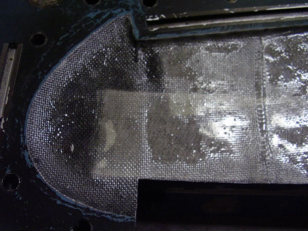
Upper Wing Skin #1
I wonder if I could introduce a two part pourable closed cell urethane foam into the brass fittings and get it to react slowly enough to avoid voids...maybe at a 2lb/ft^3 density. I've tried before with limited success, but first we'll try a simpler approach to see where we stand.
I wonder if I could introduce a two part pourable closed cell urethane foam into the brass fittings and get it to react slowly enough to avoid voids...maybe at a 2lb/ft^3 density. I've tried before with limited success, but first we'll try a simpler approach to see where we stand.
01-08-2013, 07:44 PM
#478

Slow the urethane foam will create an extremely strong wing. Like a a park bench really. But it will be too heavy for this application once you have a completed air frame.
Unless you want a really strong static model.
We did that in 1991 with our 63" span all composite Hawker Hurricane just to see what happens. It was heavy. Used it for extra seating in the lunch room.
Steve
Unless you want a really strong static model.
We did that in 1991 with our 63" span all composite Hawker Hurricane just to see what happens. It was heavy. Used it for extra seating in the lunch room.
Steve
01-09-2013, 11:18 AM
#479
Senior Member
Thread Starter
Join Date: Apr 2007
Location: Toronto,
ON, CANADA
Posts: 757
Likes: 0
Received 0 Likes
on
0 Posts
Thanks Steve,
I was thinking about filling my cavity with water and then emptying it into a graduated cylinder in order to get an accurate estimate in volume. The flap bay geometry should provide a whole bunch of strength in the root area so perhaps creating a cavity for foam just in the area of the ailerons would be enough to prevent twist.
Do you recall what kind of density you were targeting ? For what it's worth, I don't remember anything from the 90's....
01-09-2013, 04:18 PM
#480
Slow.
You are welcome to try the foam. Not the tell you your business, but
Since the 90's we have made around 15 asst all composite warbirds. What has always worked exactly as it was designed to do, was the hollow composite wing with balsa and ply framing. Similar to the construction of the real aircraft. You can use carbon or kevlar reinforcements, but not necessary. this method never failed in flight, even to this day with our current projects. My F-104 in EDF will have the same type of wing configuration. Even my turbine F-104 version.
Your volume calculation not work well, because the two part urethane foams expand far beyond the liquid volume. The other problem with the urethane resin is that it will be expanding for quite some time after its out of the mold. It could bulge the wing causing airfoil changes and distorting the fit of the wing to the fuse, ect.
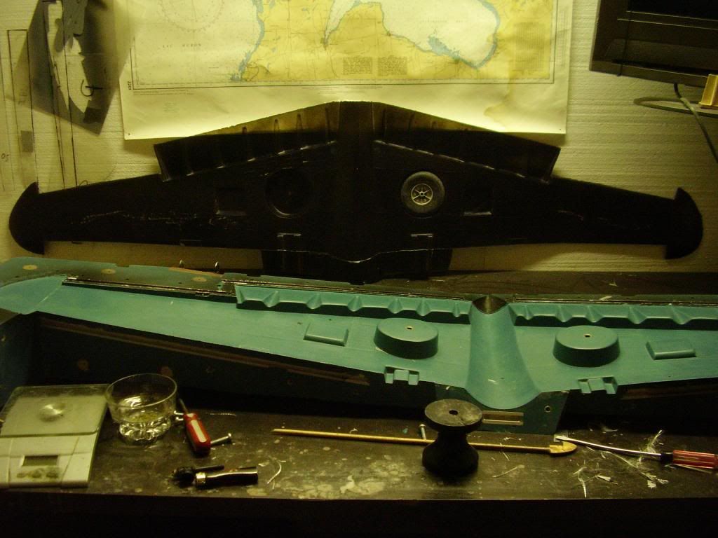
To avoid wing twist or folding, I would use the configuration shown in the pictures. Basically, the key is the spar glued to the ribs along with the glass skins kept apart by the framing. Nothing new. Remember Monocote wings?? They worked, glass wings are way better. But why doesn't everyone make glass wings?? They tried, but make them too heavy.
You have invested a lot of EVERYTHING in your project. Your mold is done far beyond the stresses it will see, which is not a problem. But over engineered.
If I may suggest,......
Your lay ups are too wet. That equals weight. Also, more epoxy is not good for the glass. It weakens the structure. Your fuse with the camouflage colors in the epoxy was a nice layup challenge , but not a good fuse for flight. Next one, clean light lay up then paint it.
You can be way lighter and stronger with a 4oz and a 6oz placed correctly with proper amount of epoxy. Also your mold configuration as you have made it, is a difficult lay up. As you may have notice by now, you have too many corners/"humps" in your mold. This creates the need for patches and fillers. Weight.
I would lay up my wing in either 2- 6oz, or a 4oz and 6oz one piece layup. Design a frame and your done. The flap details I would use a very light glass just to minimize the need for filler.
I guess once your P-40 is properly Cg'ed, it will be in the 8-10lbs range. I have the Topflite P-40 your model is off of. I also had the red box version of the Topflite P-40. it took a ton of ballast in the nose once the gear were rotated back. Don't remember the finished weight though.
The problem is to get an air frame out of the molds that lands safely.
Again, great effort, but don't over engineer. It's just weight.
As one of the best Structural engineers once said, " The difference between a good engineer and a bad engineer is the good one does not over engineer for the design"
Again, what easily works for me and my little group of composite flying friends may not work for you, but it could be a short cut to a bad ***** flying composite for you.
Steve
You are welcome to try the foam. Not the tell you your business, but
Since the 90's we have made around 15 asst all composite warbirds. What has always worked exactly as it was designed to do, was the hollow composite wing with balsa and ply framing. Similar to the construction of the real aircraft. You can use carbon or kevlar reinforcements, but not necessary. this method never failed in flight, even to this day with our current projects. My F-104 in EDF will have the same type of wing configuration. Even my turbine F-104 version.
Your volume calculation not work well, because the two part urethane foams expand far beyond the liquid volume. The other problem with the urethane resin is that it will be expanding for quite some time after its out of the mold. It could bulge the wing causing airfoil changes and distorting the fit of the wing to the fuse, ect.
To avoid wing twist or folding, I would use the configuration shown in the pictures. Basically, the key is the spar glued to the ribs along with the glass skins kept apart by the framing. Nothing new. Remember Monocote wings?? They worked, glass wings are way better. But why doesn't everyone make glass wings?? They tried, but make them too heavy.
You have invested a lot of EVERYTHING in your project. Your mold is done far beyond the stresses it will see, which is not a problem. But over engineered.
If I may suggest,......
Your lay ups are too wet. That equals weight. Also, more epoxy is not good for the glass. It weakens the structure. Your fuse with the camouflage colors in the epoxy was a nice layup challenge , but not a good fuse for flight. Next one, clean light lay up then paint it.
You can be way lighter and stronger with a 4oz and a 6oz placed correctly with proper amount of epoxy. Also your mold configuration as you have made it, is a difficult lay up. As you may have notice by now, you have too many corners/"humps" in your mold. This creates the need for patches and fillers. Weight.
I would lay up my wing in either 2- 6oz, or a 4oz and 6oz one piece layup. Design a frame and your done. The flap details I would use a very light glass just to minimize the need for filler.
I guess once your P-40 is properly Cg'ed, it will be in the 8-10lbs range. I have the Topflite P-40 your model is off of. I also had the red box version of the Topflite P-40. it took a ton of ballast in the nose once the gear were rotated back. Don't remember the finished weight though.
The problem is to get an air frame out of the molds that lands safely.
Again, great effort, but don't over engineer. It's just weight.
As one of the best Structural engineers once said, " The difference between a good engineer and a bad engineer is the good one does not over engineer for the design"
Again, what easily works for me and my little group of composite flying friends may not work for you, but it could be a short cut to a bad ***** flying composite for you.
Steve
01-10-2013, 12:28 AM
#481
Senior Member
Thread Starter
Join Date: Apr 2007
Location: Toronto,
ON, CANADA
Posts: 757
Likes: 0
Received 0 Likes
on
0 Posts
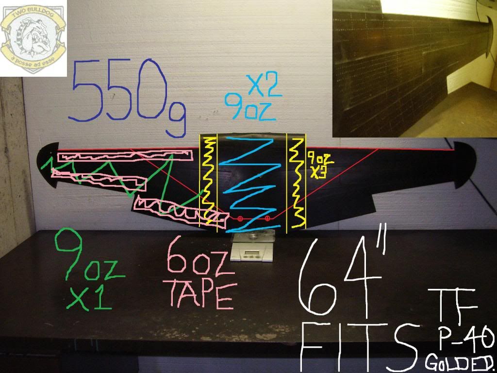
Thanks Steve - you hit the nail on the head - I'm trying to eliminate all of that wood cutting 
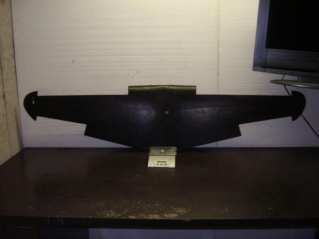
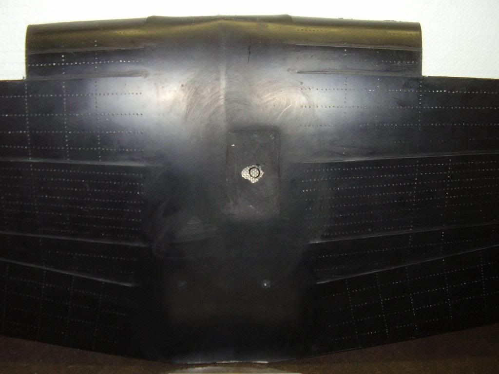
550 grams or 19.4 ounces or 1.2 lbs - room for improvement
550 grams or 19.4 ounces or 1.2 lbs - room for improvement
01-10-2013, 07:12 AM
#482
The Corsair wing may be a bit much for an example.
The configuration more similar to your wing would be our 109, except for the gear. 1/4" balsa mostly except for LG plate, that's 3/16"5 ply.
Very few pieces in the wing frame. Flies very well and forgiving on landing. Take offs are still typical 109, hard.
Steve
The configuration more similar to your wing would be our 109, except for the gear. 1/4" balsa mostly except for LG plate, that's 3/16"5 ply.
Very few pieces in the wing frame. Flies very well and forgiving on landing. Take offs are still typical 109, hard.
Steve
 01-12-2013, 09:18 PM
#485
Senior Member
Thread Starter
Join Date: Apr 2007
Location: Toronto,
ON, CANADA
Posts: 757
Likes: 0
Received 0 Likes
on
0 Posts
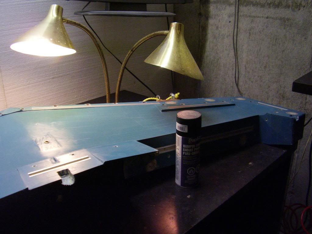
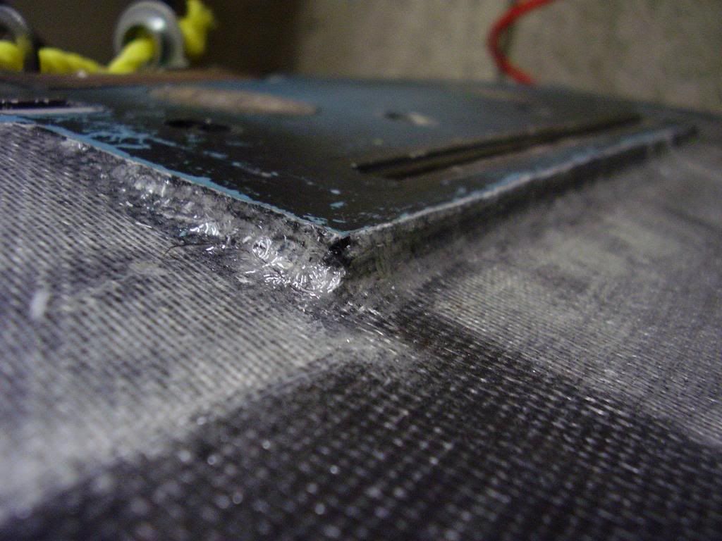
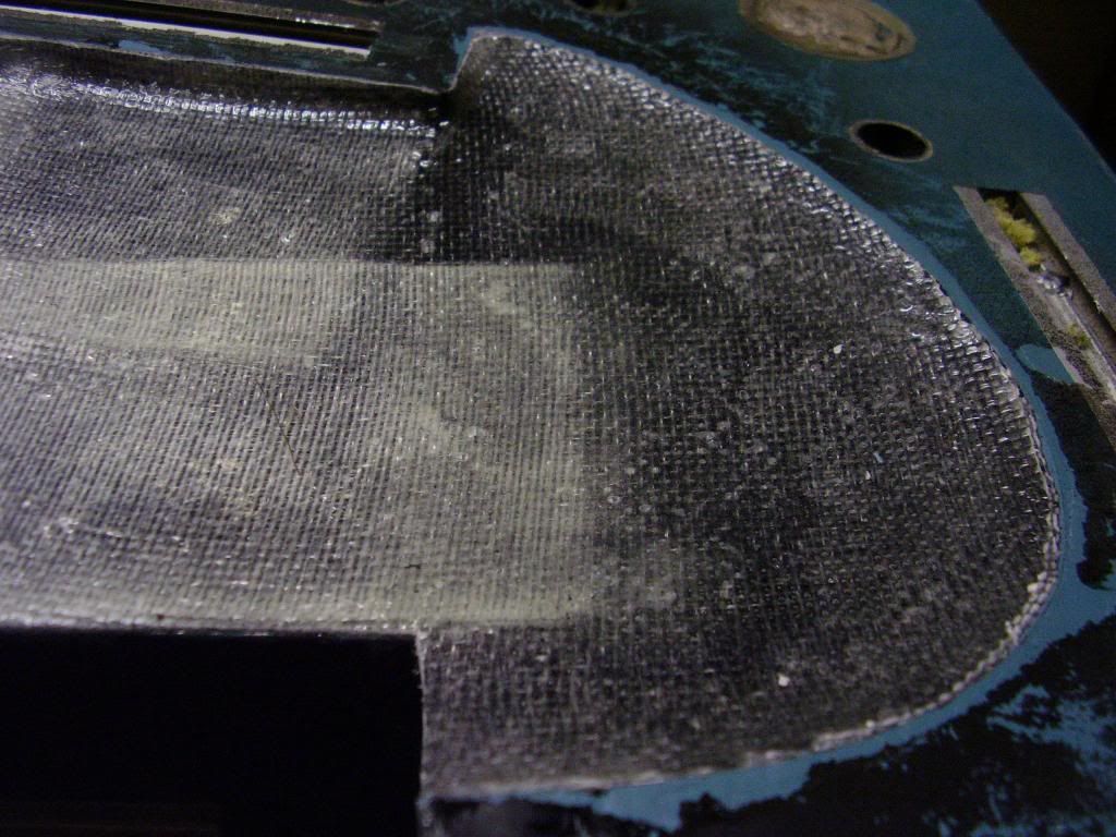
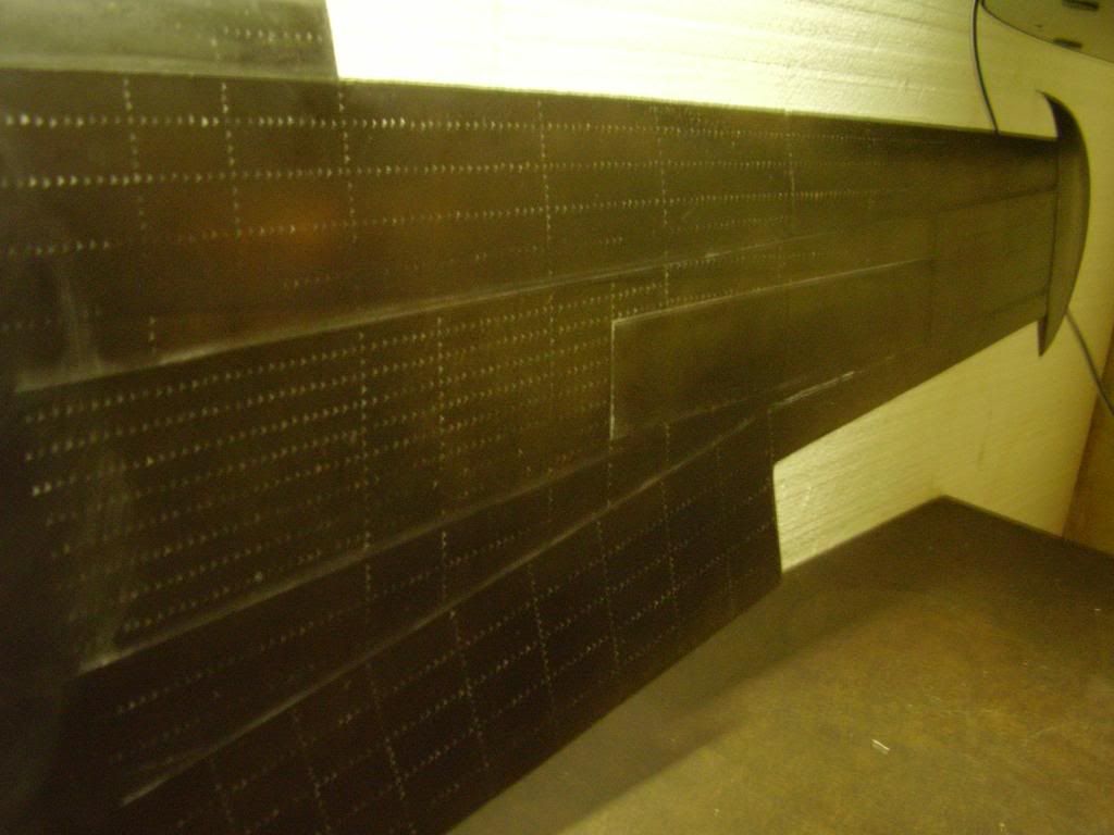
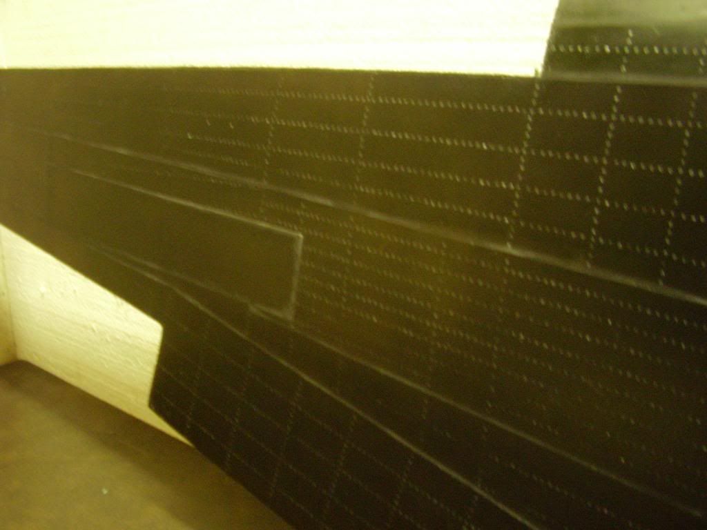
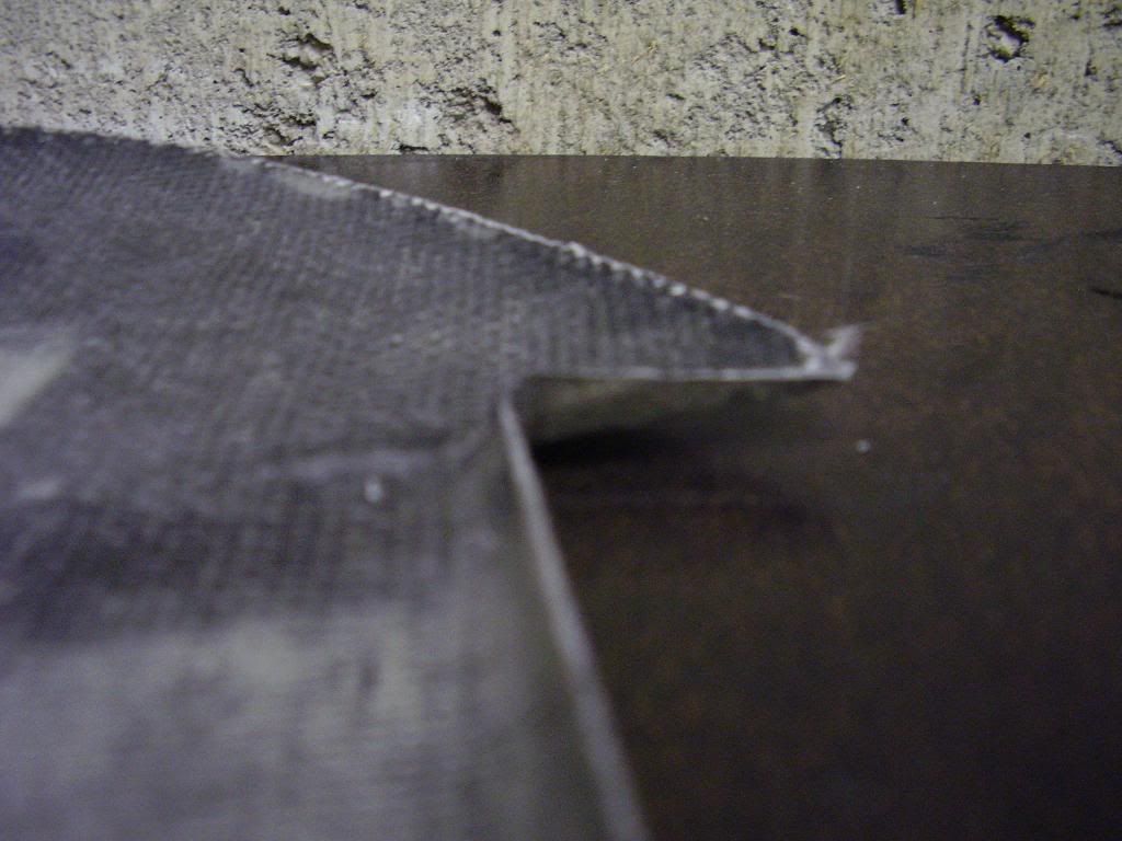
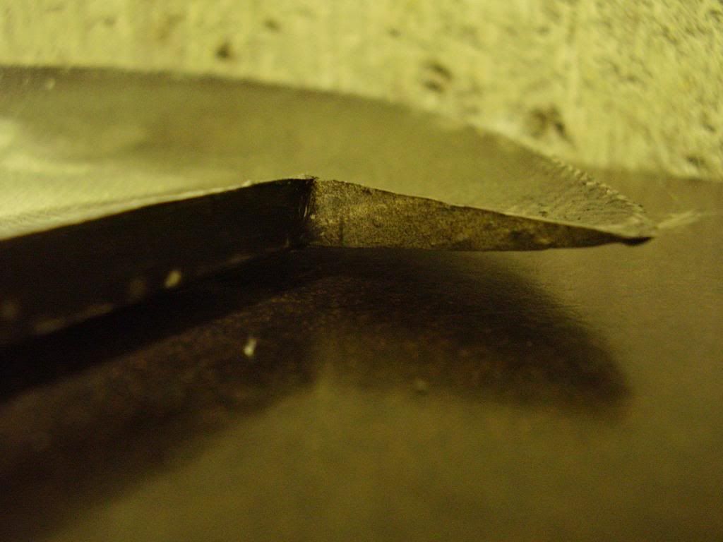
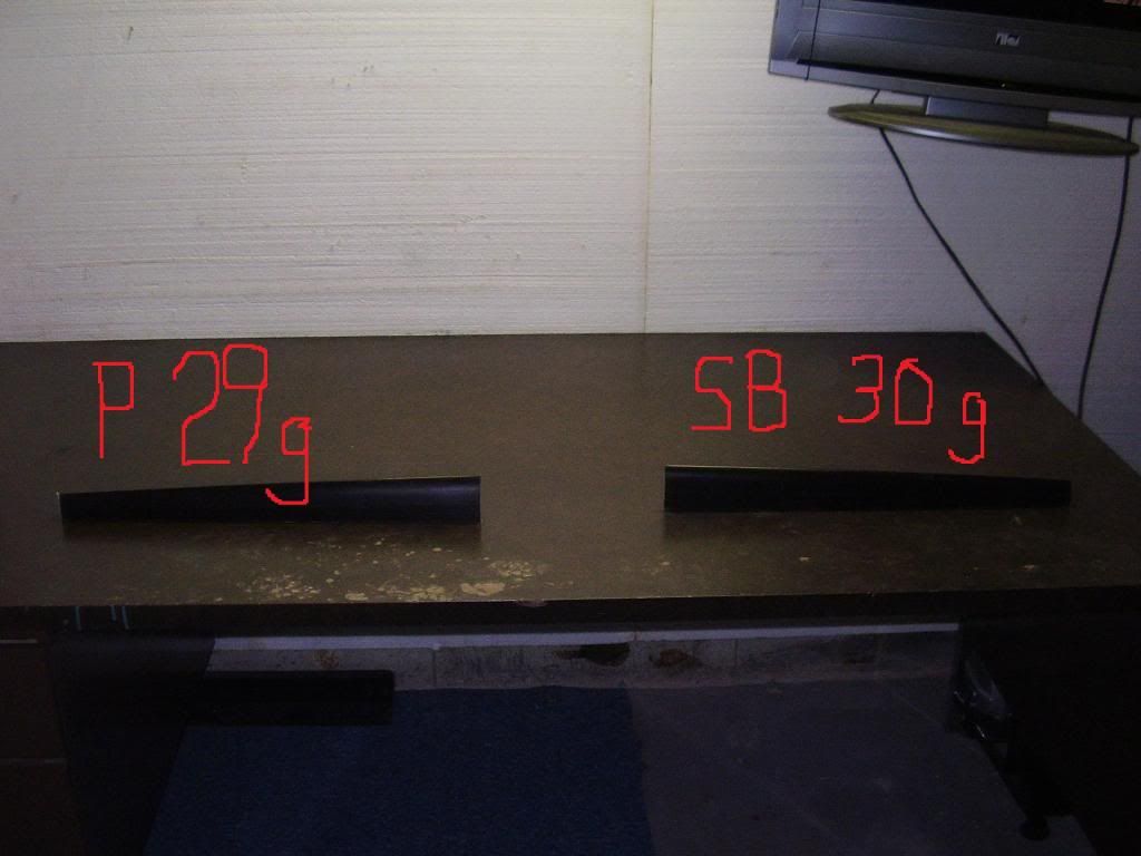
These leading edges should be nice and light.
All they have to do is deflect air over the spar.
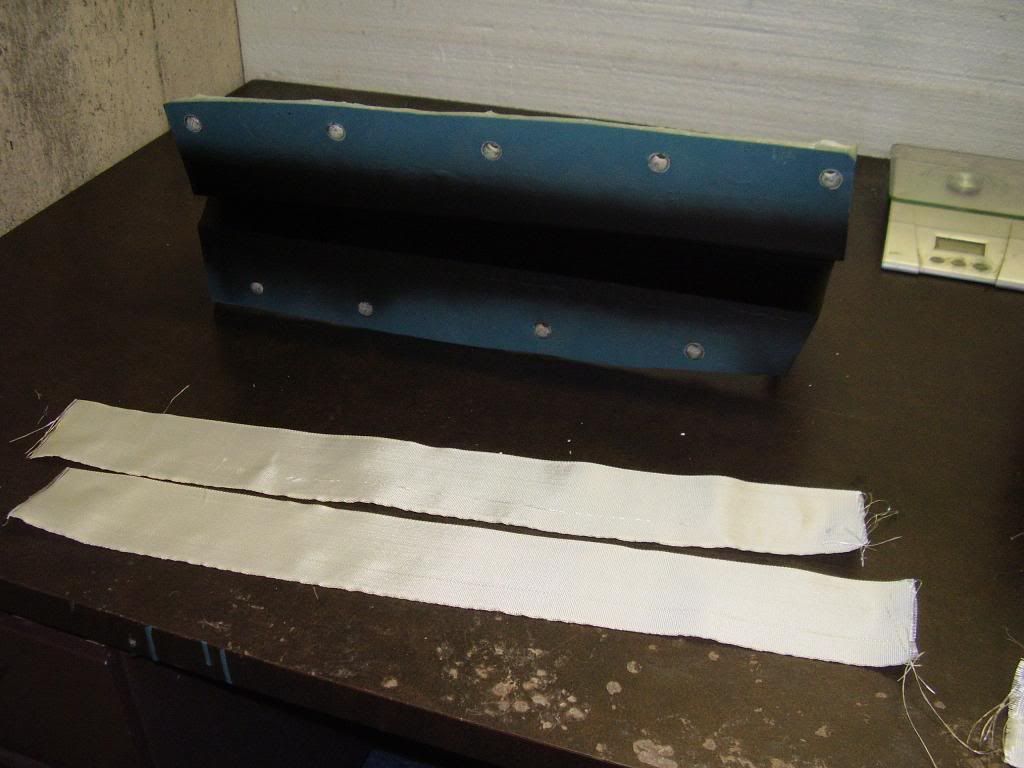
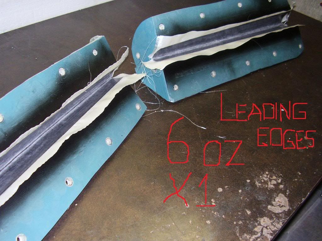
All they have to do is deflect air over the spar.
 05-21-2013, 06:54 AM
#487
Senior Member
Thread Starter
Join Date: Apr 2007
Location: Toronto,
ON, CANADA
Posts: 757
Likes: 0
Received 0 Likes
on
0 Posts
<xml><w:WordDocument><w:View>Normal</w:View><w:Zoom>0</w:Zoom><w oNotOptimizeForBrowser /></w:WordDocument></xml>
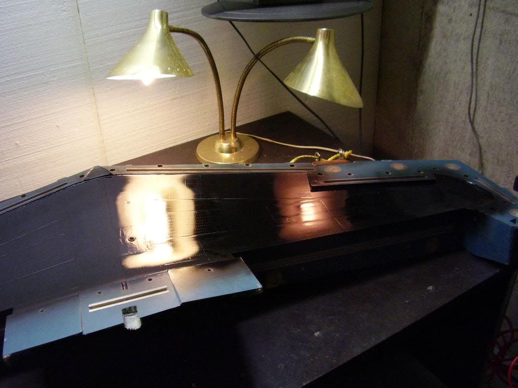
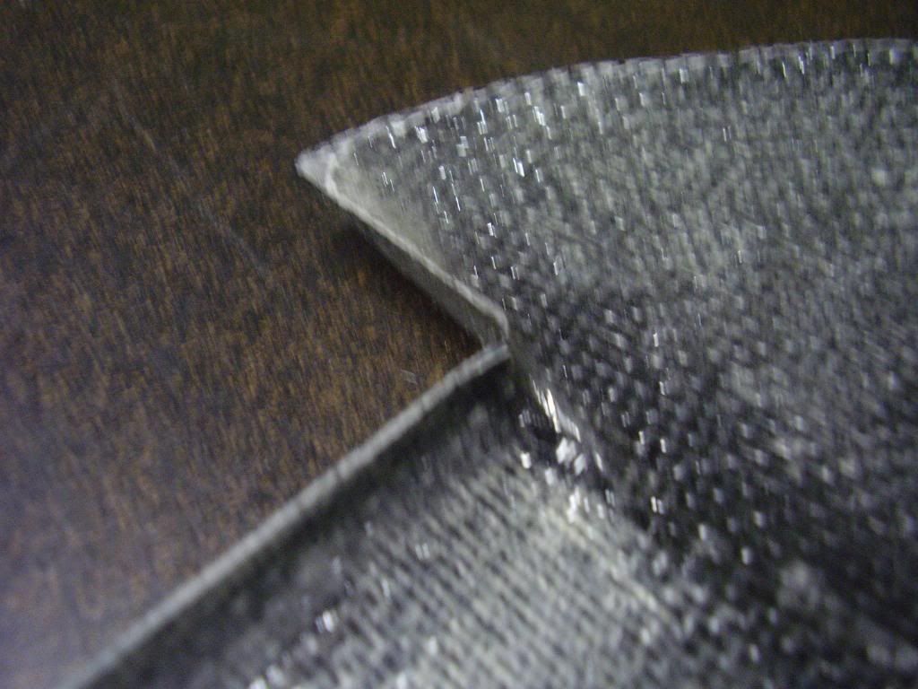
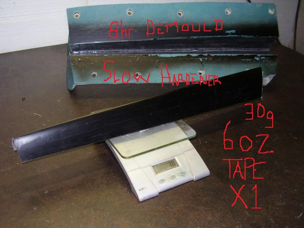
oNotOptimizeForBrowser /></w:WordDocument></xml>So strong they’re scary and so light it makes you look twice when you pick one up…
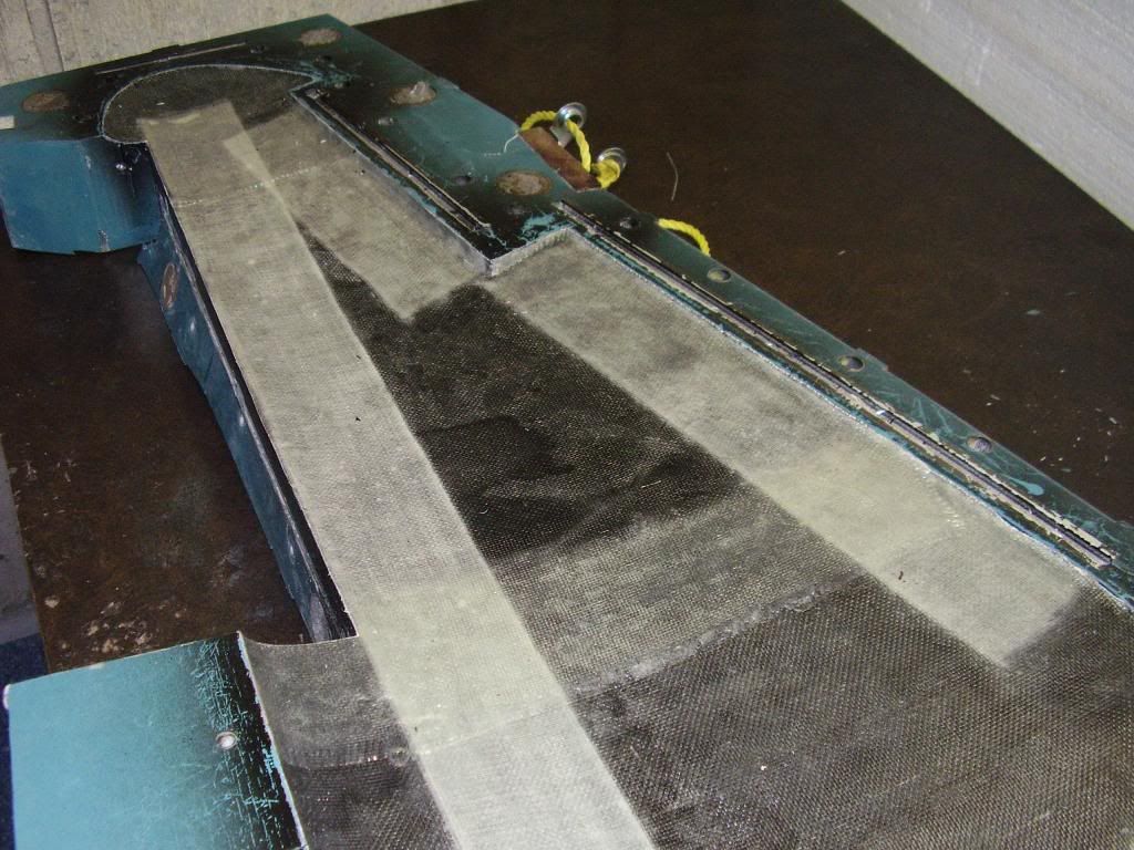
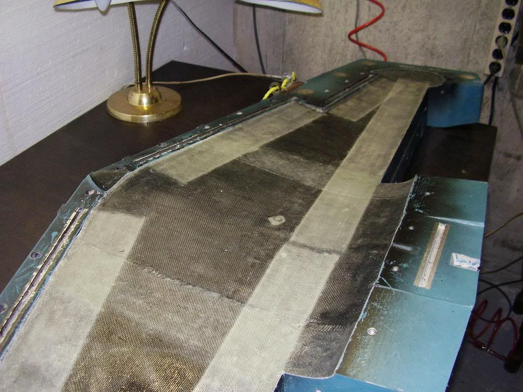
Al/GRP Laminated D-box Leading Edges


 05-24-2013, 01:02 PM
#489
Senior Member
Thread Starter
Join Date: Apr 2007
Location: Toronto,
ON, CANADA
Posts: 757
Likes: 0
Received 0 Likes
on
0 Posts
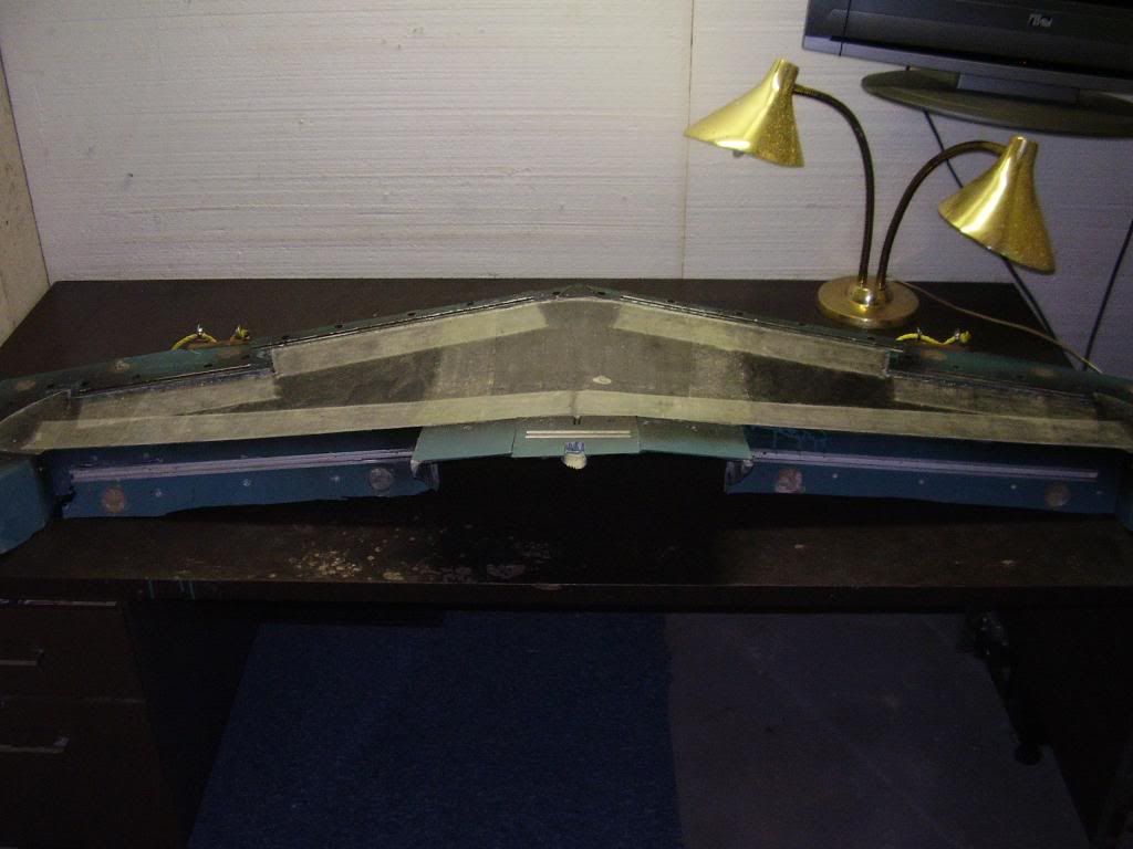
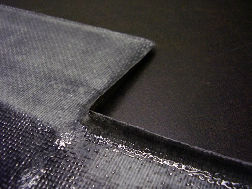
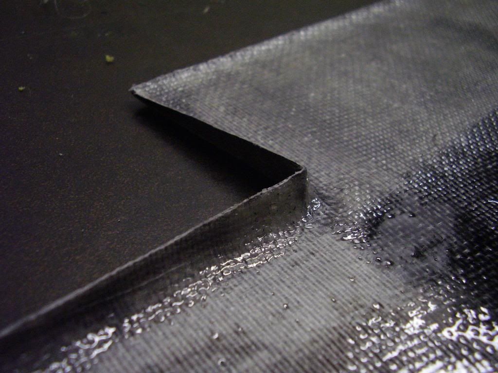
Crude initial hand layup 410 grams or 14.5 Ounces or 0.9 lb
Part looks great. Still stiffening up a bit.
Part looks great. Still stiffening up a bit.


 05-25-2013, 07:14 AM
#490
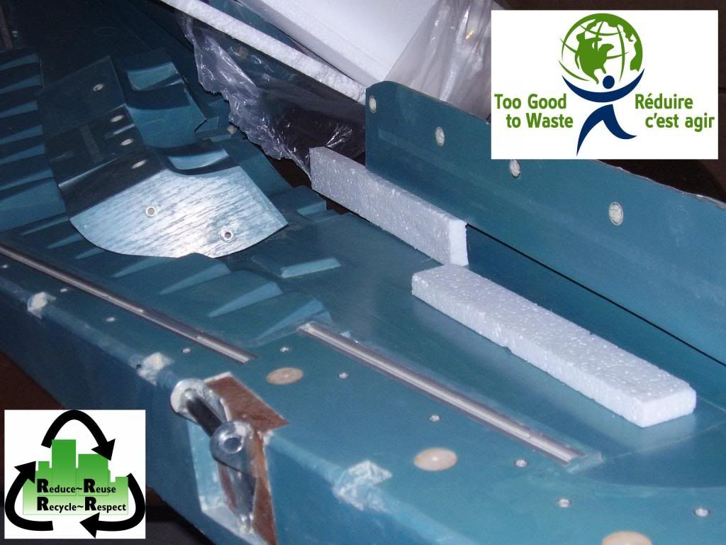
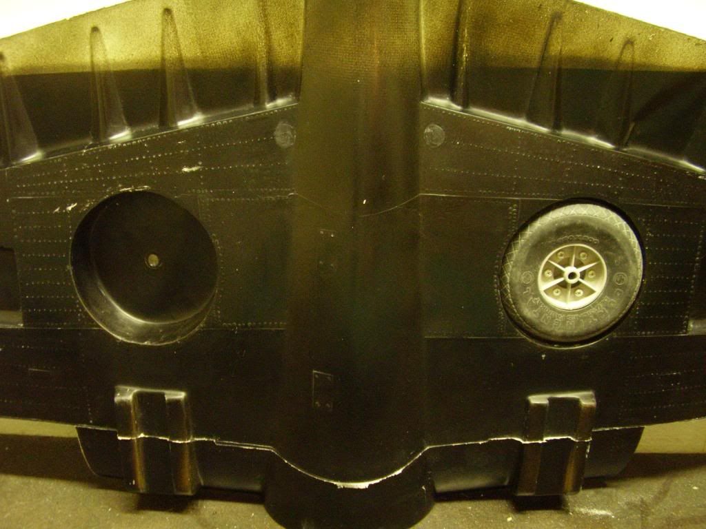
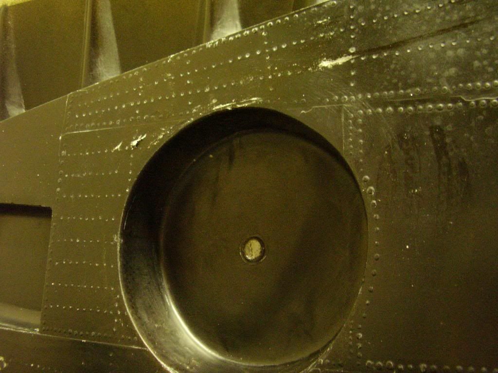
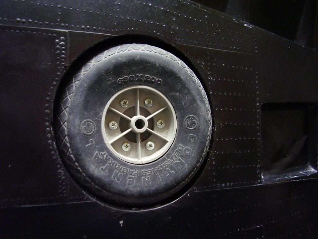
Nice work Slow. I would have given the wheel well more clearance. They tend to hang up on the rotating type. Maybe a smaller tire?? My 2centss.
Keep it light, the P-40 is a nose heavy bird in the RC model configuration. Especially when the gear rotate back.
Keep it under 9lbs and keep up the airspeed when landing. At first ......
Good luck
Steve
Keep it light, the P-40 is a nose heavy bird in the RC model configuration. Especially when the gear rotate back.
Keep it under 9lbs and keep up the airspeed when landing. At first ......
Good luck
Steve
05-25-2013, 07:44 AM
#491
Senior Member
Thread Starter
Join Date: Apr 2007
Location: Toronto,
ON, CANADA
Posts: 757
Likes: 0
Received 0 Likes
on
0 Posts
thanks Steve - that's a 4" wheel for a scale appearance, but the initial plan called for 3" - I've got them around here too
the draft on the well and the radiused wall on the tire may be enough to guide things into place - if not I'll just use 3" like others I've seen
the draft on the well and the radiused wall on the tire may be enough to guide things into place - if not I'll just use 3" like others I've seen
 08-07-2015, 04:50 PM
#493

My Feedback: (1)
hey are you still making parts for the top flite p-40?
I now have almost finished my associates in mechanical engineering and design and currently work as a machinist programming cnc mills, setting up stock and tooling, operating, making plastic injection molds. that kind of thing....
I now have almost finished my associates in mechanical engineering and design and currently work as a machinist programming cnc mills, setting up stock and tooling, operating, making plastic injection molds. that kind of thing....

