


Amp Test Question
 01-03-2015, 02:56 PM
#1
Junior Member
Thread Starter
Join Date: Jan 2015
Posts: 3
Likes: 0
Received 0 Likes
on
0 Posts
I am in need of Amp measurements to establish power needs of motor/drive line combination on a proof of concept electric model. A test was set up that produced baffling results. In a nut shell, the load was huge and the motor was not even on.
The setup included one nimh 1600 battery, an ESC, Electriflight 600 motor and a 20 amp amp gauge wired in series.
With the transmitter on and the throttle off., I proceeded to attach the last of the above circuit. There was an arc and the gauge pegged at 20.
Are there any suggestions on how this happens?
 01-03-2015, 05:17 PM
#2

The first question is: You are sure the meter was 'in line'. Put across the + and - leads the meter would short the battery.
Second question, assuming the meter was indeed in line, was this an instantaneous current and then all was ok.. This would be quite normal as when you connect an ESC the battery 'charges' the ESC's capacitors giving rise to quite a substantial spark (and current) as you make contact.
If it maintained a 20A+ current then I would suggest the ESC is almost certainly broken.
01-04-2015, 07:04 AM
#3
Junior Member
Thread Starter
Join Date: Jan 2015
Posts: 3
Likes: 0
Received 0 Likes
on
0 Posts
The circuit uses "T" connectors. To clean things up, I placed the same connectors on the amp gauge so there is no question regarding the wiring. The 20+ amp draw was constant. I have since tested the circuit without the gauge to find that nothing was damaged and the components work. I am lucky but I still have no solution as to what causes the huge amps. The only active part is the RC receiver and the ESC.
01-04-2015, 08:50 AM
#4
If it works normally without the gauge then surely the gauge itself (or how it is wired up) must be the problem.
It is a 'Watt meter' specifically designed for RC use. Something like this?
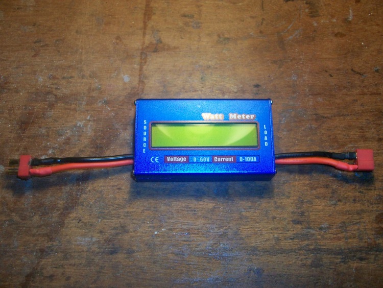
A picture of your gauge and a maybe a diagram of how you wired it up might help.
It is a 'Watt meter' specifically designed for RC use. Something like this?
A picture of your gauge and a maybe a diagram of how you wired it up might help.
01-04-2015, 11:19 AM
#5
Junior Member
Thread Starter
Join Date: Jan 2015
Posts: 3
Likes: 0
Received 0 Likes
on
0 Posts
Your line of questioning helped me. I retraced the circuit to find that one connector on the gauge was backwards. This caused reverse polarity. I am lucky that esc had protection for this. Thanx for your help quorneng.


