


Allure by Bryan Hebert

 03-15-2015, 08:40 PM
#252

Thread Starter

Join Date: Aug 2005
Location: Sydney, AUSTRALIA
Posts: 1,341
Likes: 0
Received 0 Likes
on
0 Posts
We have an event at Wingham the week after the NATS. Perhaps come up for the day?
Cheers,
Jason.
03-16-2015, 12:30 AM
#254
Member
Join Date: Apr 2007
Location: TakapauSHB, NEW ZEALAND
Posts: 67
Likes: 0
Received 0 Likes
on
0 Posts
") 03-16-2015, 06:25 PM
03-16-2015, 06:25 PM
#255
Thread Starter
Join Date: Aug 2005
Location: Sydney, AUSTRALIA
Posts: 1,341
Likes: 0
Received 0 Likes
on
0 Posts
Last night the stab servo trays were glued into position and one BLS153 was mounted. With NMP Dual Axis Ball Ends and CK Aero control horns the linkage needs to be 82mm long. Again, the pivot point is ahead of the hinge line and the horns are the 17mm version.
Cheers,
Jason.
03-18-2015, 07:39 AM
#259
My Feedback: (1)

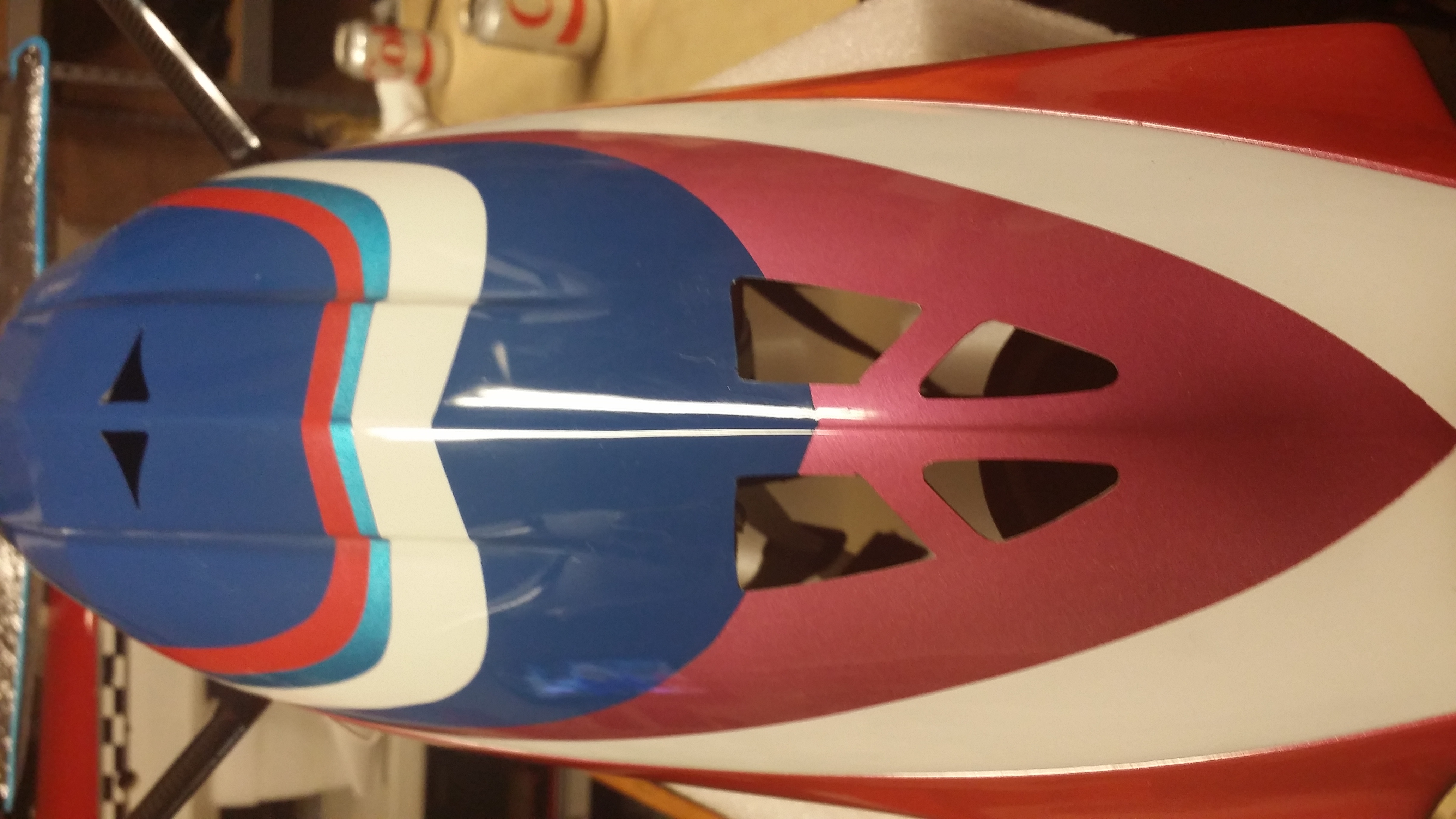
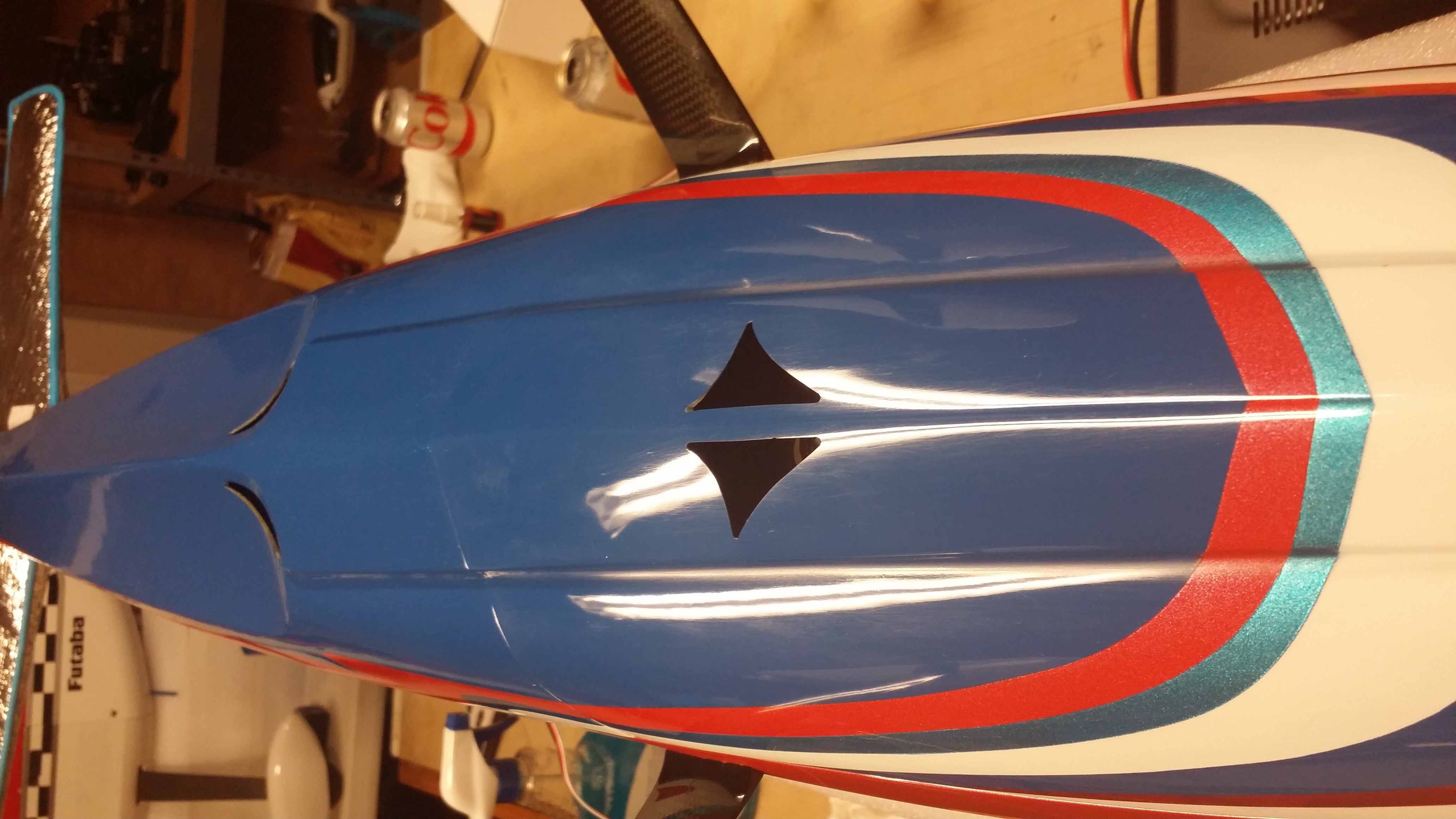
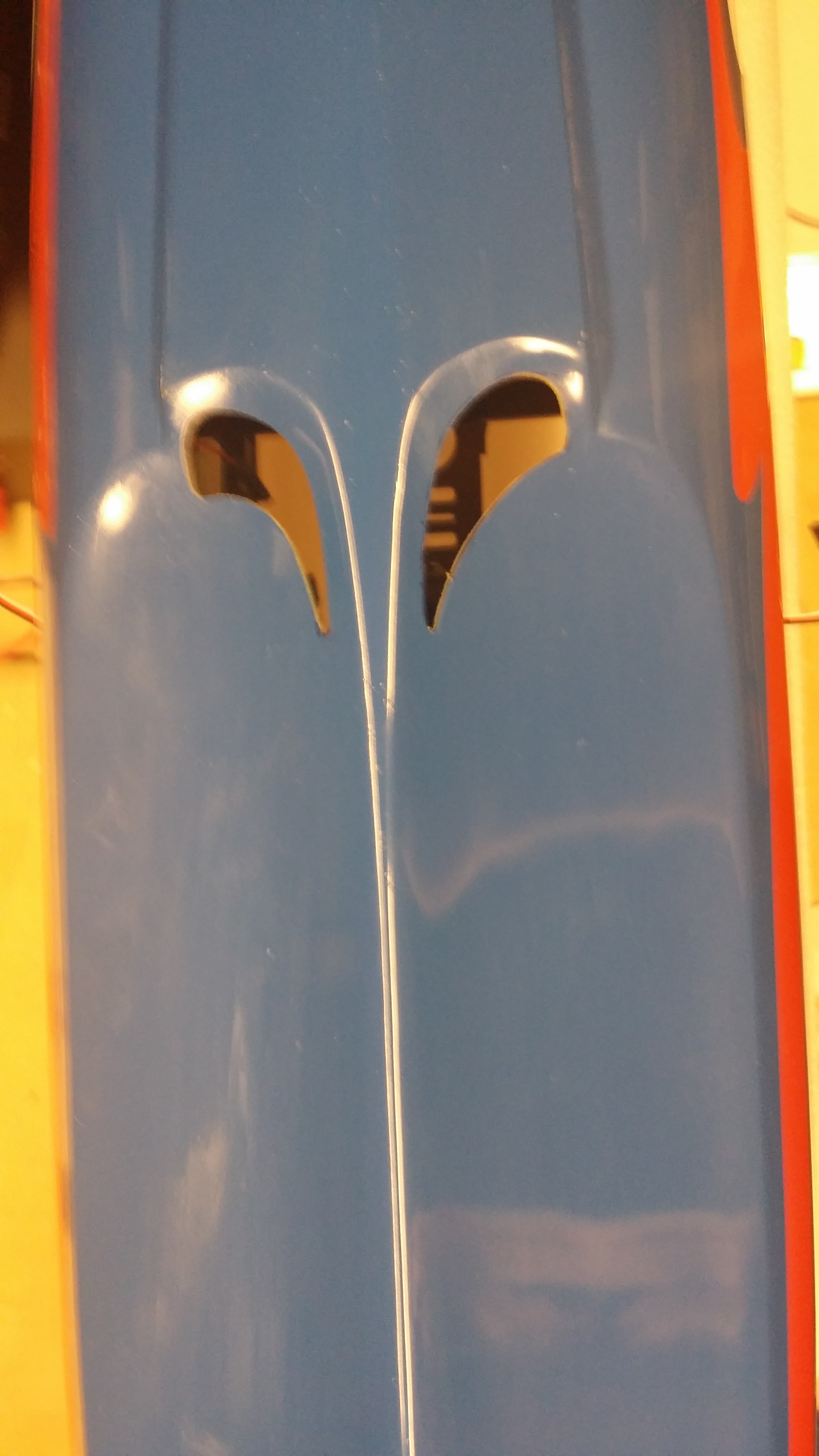
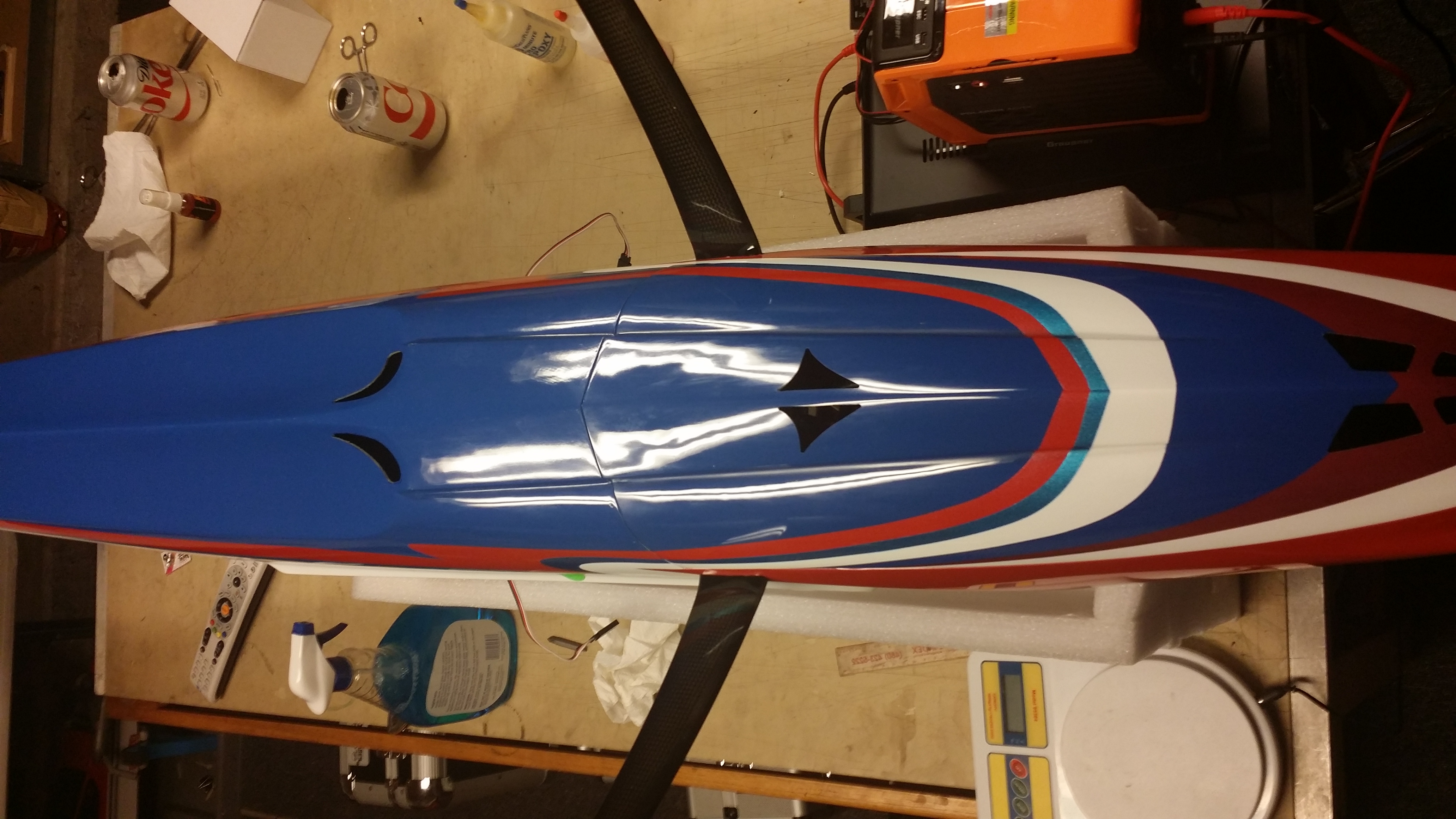
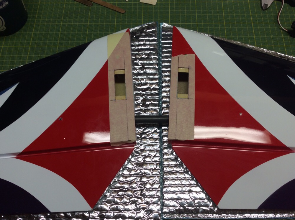
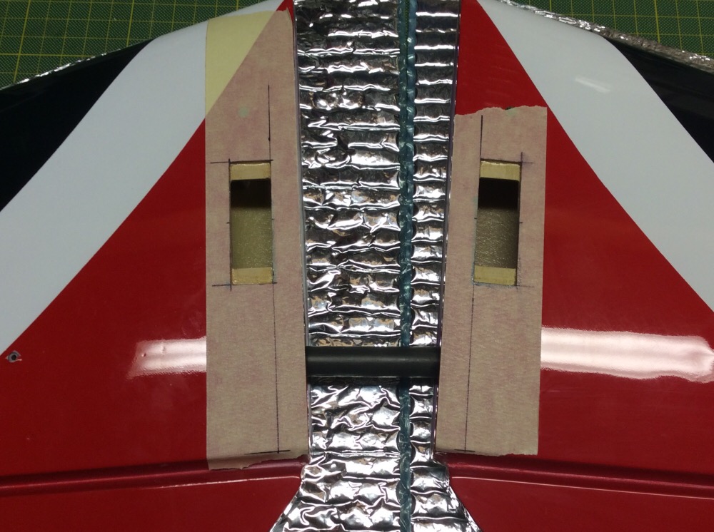
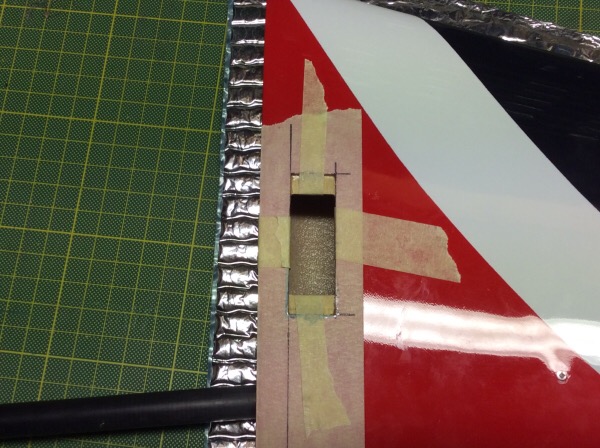
Jason had contacted me yesterday concerning cooling exhaust vents that we placed in the Contra Allure prototype. I have included a few pictures to show the placement of the vents on the bottom of the aircraft. Keep in mind, the Contra prototype has a removable chin cowl where the production Contra Allure does not. This may affect where you decide to place the vents. The most important thing is that your "exhaust" volume is twice that of your "intake". This creates a good airflow. Although I haven't seen a real-life production model yet, I've seen a few pictures and Jason told me that the holes were already there in the cheek cowls for exhaust. The attached pictures are simply of the bottom from the nose looking back. Please excuse the mess on the work table 
 03-18-2015, 12:07 PM
#261

Join Date: Apr 2006
Location: Plano,
TX
Posts: 29
Likes: 0
Received 0 Likes
on
0 Posts
Simply Awesome....there are no other words to describe it. Both Allure paint schemes in posts #228 and #257 are just awesome! Bryan/Brett this is creative genius at its finest...keep up the good work.
03-18-2015, 12:32 PM
#262
Thread Starter
Join Date: Aug 2005
Location: Sydney, AUSTRALIA
Posts: 1,341
Likes: 0
Received 0 Likes
on
0 Posts
Jason had contacted me yesterday concerning cooling exhaust vents that we placed in the Contra Allure prototype. I have included a few pictures to show the placement of the vents on the bottom of the aircraft. Keep in mind, the Contra prototype has a removable chin cowl where the production Contra Allure does not. This may affect where you decide to place the vents. The most important thing is that your "exhaust" volume is twice that of your "intake". This creates a good airflow. Although I haven't seen a real-life production model yet, I've seen a few pictures and Jason told me that the holes were already there in the cheek cowls for exhaust. The attached pictures are simply of the bottom from the nose looking back. Please excuse the mess on the work table
Thanks for posting the pictures mate. Your bench looks spotless compared to my shop at the moment.
I believe these cooling holes or something similar will be done in the factory for future deliveries. Correct me if I'm wrong Bryan.
The stab servo cut-outs will also be done in the factory for future deliveries.
Cheers,
Jason.
03-18-2015, 03:30 PM
#263
My Feedback: (3)
This is right Ewan, would be interesting to stick a .60ci Pattern model next to and Allure or Essence....
Last night the stab servo trays were glued into position and one BLS153 was mounted. With NMP Dual Axis Ball Ends and CK Aero control horns the linkage needs to be 82mm long. Again, the pivot point is ahead of the hinge line and the horns are the 17mm version.
Cheers,
Jason.
Last night the stab servo trays were glued into position and one BLS153 was mounted. With NMP Dual Axis Ball Ends and CK Aero control horns the linkage needs to be 82mm long. Again, the pivot point is ahead of the hinge line and the horns are the 17mm version.
Cheers,
Jason.
I always thought the pivot point was to be placed on the hinge (center) line.
Thank you very much.
03-18-2015, 04:34 PM
#264
Thread Starter
Join Date: Aug 2005
Location: Sydney, AUSTRALIA
Posts: 1,341
Likes: 0
Received 0 Likes
on
0 Posts
Hi ITC,
It’s not a stupid question at all. When I did the aileron horns, I assumed the pivot point needed to be right over the hinge line. I sent a picture of what I had done to Bryan and that’s when I was advised the front edge of the horn needed to be right on the edge of the aileron bevel. Bryan advises that his CK Aero control horns were designed in a control linkage program to have perfect setup for equal travel up and down when mounted on the edge of the aileron.
Cheers,
Jason.
03-18-2015, 11:48 PM
#265
Hi ITC,
It’s not a stupid question at all. When I did the aileron horns, I assumed the pivot point needed to be right over the hinge line. I sent a picture of what I had done to Bryan and that’s when I was advised the front edge of the horn needed to be right on the edge of the aileron bevel. Bryan advises that his CK Aero control horns were designed in a control linkage program to have perfect setup for equal travel up and down when mounted on the edge of the aileron.
Cheers,
Jason.
It’s not a stupid question at all. When I did the aileron horns, I assumed the pivot point needed to be right over the hinge line. I sent a picture of what I had done to Bryan and that’s when I was advised the front edge of the horn needed to be right on the edge of the aileron bevel. Bryan advises that his CK Aero control horns were designed in a control linkage program to have perfect setup for equal travel up and down when mounted on the edge of the aileron.
Cheers,
Jason.
Hi Jason,
Would that not depend on the depth of the bevel - ie ; the distance from 'the edge' to the hinge pivot ??
The control attachment looks very far forward on the elevator above - might be camera angle !?
Relative heights are also in play - eg; a sunken elevator servo horn V a raised one like yours (think tangents).
Brian
PS ; I really like the WC scheme - I think it's great on a lot of levels - a bigger file version of the photos would be good ! The switch in canopy colour also works very well.
Last edited by serious power; 03-19-2015 at 12:41 AM. Reason: Addition
03-19-2015, 04:06 PM
#269
Thread Starter
Join Date: Aug 2005
Location: Sydney, AUSTRALIA
Posts: 1,341
Likes: 0
Received 0 Likes
on
0 Posts
Hi Jason,
Would that not depend on the depth of the bevel - ie ; the distance from 'the edge' to the hinge pivot ??
The control attachment looks very far forward on the elevator above - might be camera angle !?
Relative heights are also in play - eg; a sunken elevator servo horn V a raised one like yours (think tangents).
Brian
PS ; I really like the WC scheme - I think it's great on a lot of levels - a bigger file version of the photos would be good ! The switch in canopy colour also works very well.
There are probably a number of factors that may influence the position of the horns. I'm happy to go with with what Bryan advises though.... The pictures probably exaggerate things a little. This photo is probably better. The pivot point is less than 1/4" forward of the hinge line.
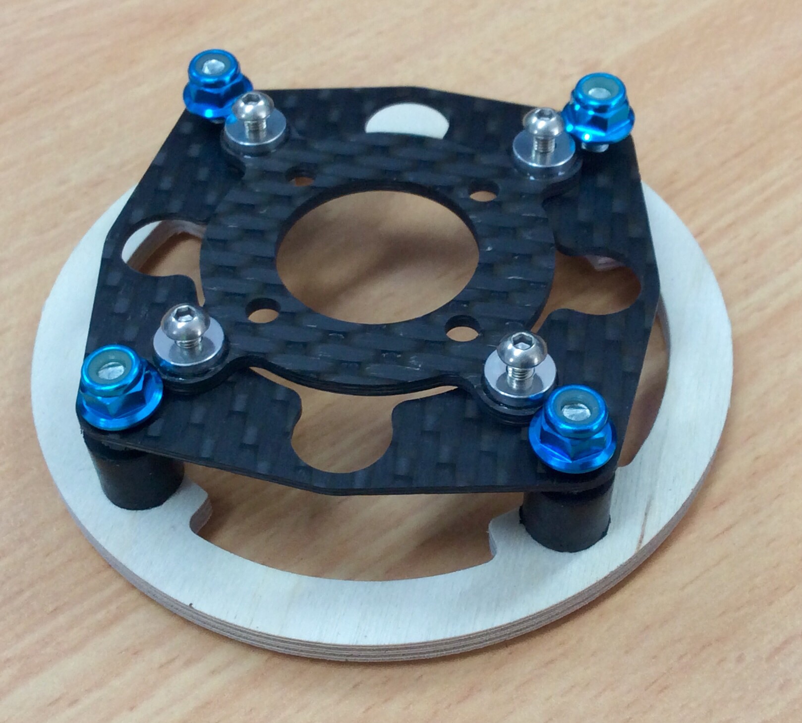
Ralph has finished my CRS mount too. Looks real nice.
Interestingly, Ralph uses a ply firewall to reduce noise.
Cheers,
Jason.
03-19-2015, 06:25 PM
#271
Thread Starter
Join Date: Aug 2005
Location: Sydney, AUSTRALIA
Posts: 1,341
Likes: 0
Received 0 Likes
on
0 Posts
I don't have a better shot of the stab horns ATM. The current picture is taken from behind so it woul not give a true indication of the pivot point relative to the hinge line.
Cheers,
Jason.
03-20-2015, 12:40 AM
#272
Hi Jason,
Ah, ok.
Elevators need different travel up and down anyway - so once you get both exactly the same (pivot V hinge line) you will get it from the radio anyway.
However I would align to the hinge line or for under-slung elevator controls (they nearly all are) perhaps have the control pivot behind the hinge line as you will need more down travel than up.
Exactly the same is of most importance.
Best of luck with it.
Brian
03-20-2015, 01:13 PM
#274
Thread Starter
Join Date: Aug 2005
Location: Sydney, AUSTRALIA
Posts: 1,341
Likes: 0
Received 0 Likes
on
0 Posts
Ralphs mount is adjustable with shims or washers. He is providing some ply spacers with my mount to make it suitable for V1, V2 & V3 Brenner Contra drive systems. Previously, his mount was only available for the Hacker C50 motor but now Neu is available. I agree, the his work does look first class.
Looking forward to the maiden myself.
Cheers,
Jason.
03-26-2015, 11:58 AM
#275
Thread Starter
Join Date: Aug 2005
Location: Sydney, AUSTRALIA
Posts: 1,341
Likes: 0
Received 0 Likes
on
0 Posts
Hi Guys,
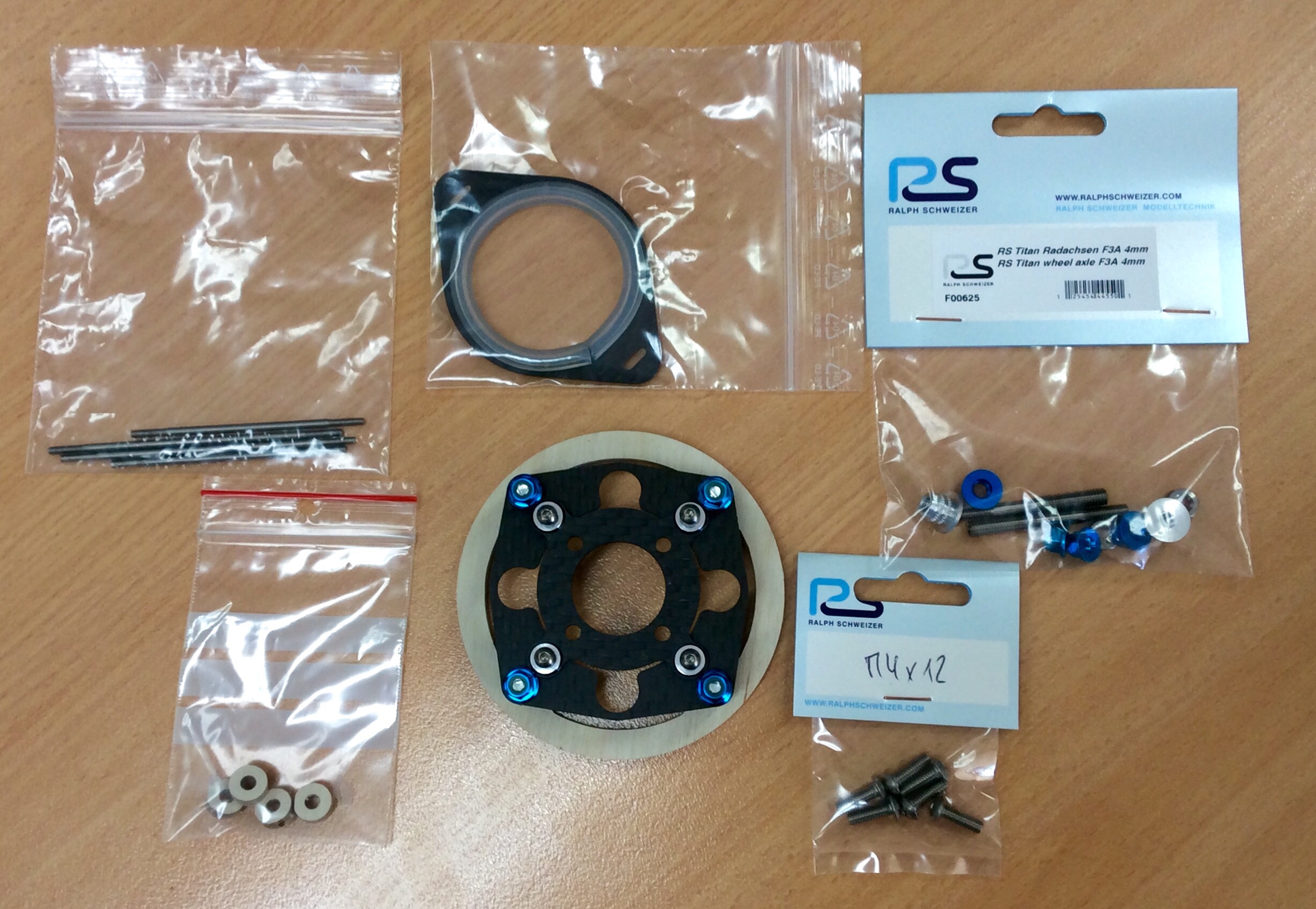
Yesterday the CRS mount, linkages and some other trick items arrived from Ralph Schweizer of Austria. Very nice gear of the highest quality!
Some real progress can be made now...
Cheers,
Jason.
Yesterday the CRS mount, linkages and some other trick items arrived from Ralph Schweizer of Austria. Very nice gear of the highest quality!
Some real progress can be made now...
Cheers,
Jason.