


Great Planes Sequence 1.20 Build Thread
 02-17-2015, 10:35 AM
#26

Thread Starter
My Feedback: (2)

Join Date: May 2002
Location: Around
Posts: 1,432
Likes: 0
Received 0 Likes
on
0 Posts
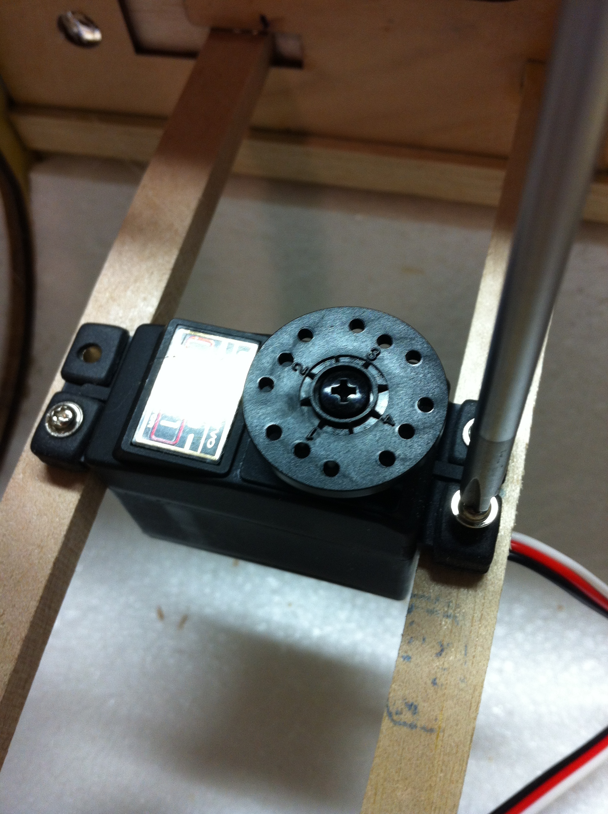
Rudder servo mounting

Measure the servo to know where to position the rail.

After measuring the servo, I marked the rail guides so I knew where to mount the rail.


A generous squeeze of the Medium CA and let it dry.

I marked the rails with the pen drill using a #55/.052 drill bit, but used a cordless drill to get through the hard wood rails.

Once drilled, screw down the servo. Remember to put the brass eyelets in from the bottom of the servo grommets.
Measure the servo to know where to position the rail.
After measuring the servo, I marked the rail guides so I knew where to mount the rail.
A generous squeeze of the Medium CA and let it dry.
I marked the rails with the pen drill using a #55/.052 drill bit, but used a cordless drill to get through the hard wood rails.
Once drilled, screw down the servo. Remember to put the brass eyelets in from the bottom of the servo grommets.
Last edited by JAS; 02-28-2015 at 08:54 AM.
 02-17-2015, 10:38 AM
#27
Thread Starter
My Feedback: (2)
Join Date: May 2002
Location: Around
Posts: 1,432
Likes: 0
Received 0 Likes
on
0 Posts
I was noticing all the cut-outs in the fuselage this morning for different switches and external safety plugs.

As well as the 2 spots for throttle servos for the glow set-ups. They'll make good lightning holes.

And removing the tabs for the elevator servos. Make sure not to cut the servo wires (I didn't do it... this time).

As well as the 2 spots for throttle servos for the glow set-ups. They'll make good lightning holes.
And removing the tabs for the elevator servos. Make sure not to cut the servo wires (I didn't do it... this time).
02-18-2015, 11:28 AM
#28
My Feedback: (21)
Join Date: Aug 2009
Location: Apple River IL
Posts: 951
Likes: 0
Received 0 Likes
on
0 Posts
Was thinking that might be the case JAS, appreciate that, maybe rig something like that up with the extensions I have. I went with carbon pushrods per your pics a few posts back, although I did add a threaded coupler. Reason being is I use a 24 yr old transmitter and am not certain if I could replicate the same elevator throw side to side accurately enough. If I can, I'll change it and not use the threaded coupler. Appreciate the pics, provides good info.
hook
hook
02-18-2015, 05:45 PM
#29

My Feedback: (18)
Join Date: Jan 2003
Location: Florida
Posts: 108
Likes: 0
Received 0 Likes
on
0 Posts
Well I got my Sequence 1.20 the other day. My only comment . I have purchase a lot of ARF's over the past 30+ years and for a $500 plane this had more wrinkles then my 93 year old mother. I spent all day ironing the wrinkles out, but one good thing it came in with no damage or parts missing. I just finished a Bill Hembel Pawnee that the instruction said you might need to re-iron the plane. The plane came in wrinkle free, did not have to touch it at all-one of the best ARF's I have ever built. It's been twenty years since I had a pattern plane. As of late I have been flying warplanes and EDF's jets.. I'll finish this plane as soon as the 1.20 Rimfire comes in and will post the out come on how it fly's.
02-19-2015, 10:03 AM
#30
My Feedback: (21)
Join Date: Aug 2009
Location: Apple River IL
Posts: 951
Likes: 0
Received 0 Likes
on
0 Posts
I picked up two of these rampage, one was a bit more wrinkled than the other but not really too bad. A quick hit with heat gun followed by the covering iron worked nicely.
Heads up on the Rimfire 1.20, check that the prop adapter mounting holes align with mounting holes on the motor can. Of the two that I have, one is off by at least about 1/32". If I rotate it around only three holes will align. On the second one, it lines up better and I can start all four socket head screws. However, I cannot get it to seat (bottom out) on the motor. I'm going to check it with a feeler gauge to see what the gap is. I will not operate the motor in either case. Called service center regarding it and they are looking into. I suspect the prop adapters were misdrilled or the jig that is used is out of tolerance. My two 1.20s were purchased within the last month. Not sure if JAS has seen this or not on his. Just FYI.
mark
02-19-2015, 10:48 AM
#31
My Feedback: (18)
Join Date: Jan 2003
Location: Florida
Posts: 108
Likes: 0
Received 0 Likes
on
0 Posts
Your correct about the holes not matching up. I opted to buy the motor mount wood package for $17 to solve this problem . I also went with a vent spinner due to the motor is now mounted behind a plate and not in the open.
02-19-2015, 05:41 PM
#32
My Feedback: (21)
Join Date: Aug 2009
Location: Apple River IL
Posts: 951
Likes: 0
Received 0 Likes
on
0 Posts
So by using the collet or set screw adapter you won't have that issue, interesting. I do have the wood mount package also, but I was using the GP aluminum mount just to set up the cowl etc. while I assemble the wood mount. From a consumer view point, we shouldn't have to spend more money to accomodate a manufacturing flaw though. I'm still curious about what Hobico services says about it.
Mark
Mark
02-27-2015, 09:44 AM
#33
Thread Starter
My Feedback: (2)
Join Date: May 2002
Location: Around
Posts: 1,432
Likes: 0
Received 0 Likes
on
0 Posts
I checked my motor and the included adapter lines up. I didn't try and screw it on as I'm going with the other mounting system instead.

Although my Sequence came with very few wrinkles, when we had our 'cold spell' last week I noticed a few more showed up. After an hour going over the whole plane with the MonoKote iron (set on 2) the wrinkles were gone. I think the cold dry air dried out the wood and it shrunk, thereby making the covering loose. Good part is once the humidity came back, all the MonoKote was nice and tight.

Although my Sequence came with very few wrinkles, when we had our 'cold spell' last week I noticed a few more showed up. After an hour going over the whole plane with the MonoKote iron (set on 2) the wrinkles were gone. I think the cold dry air dried out the wood and it shrunk, thereby making the covering loose. Good part is once the humidity came back, all the MonoKote was nice and tight.
Last edited by JAS; 02-28-2015 at 08:51 AM.
02-27-2015, 09:51 AM
#34
Thread Starter
My Feedback: (2)
Join Date: May 2002
Location: Around
Posts: 1,432
Likes: 0
Received 0 Likes
on
0 Posts
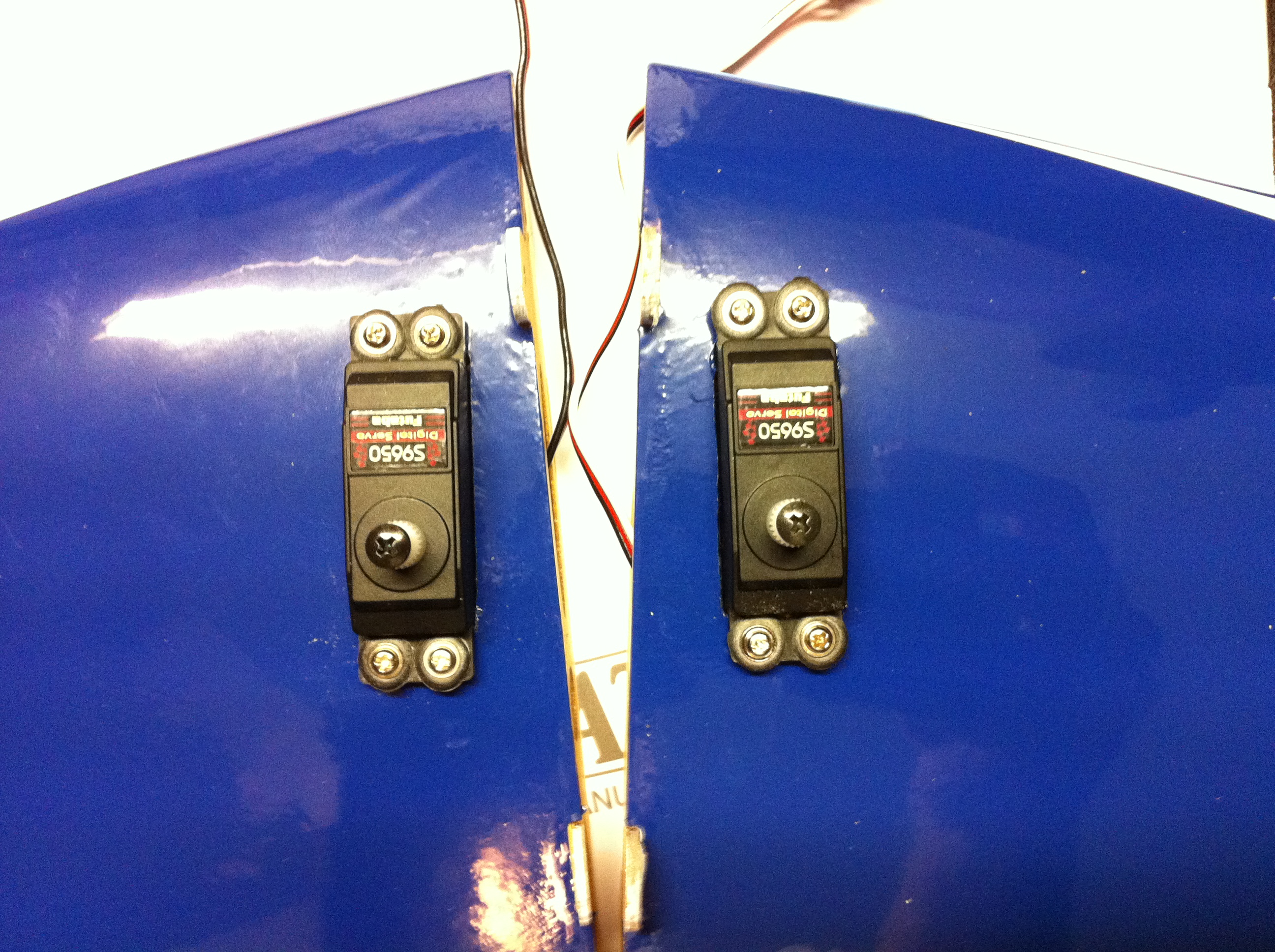
Elevator servo install.
I had one corner that was a bit tight. A quick swipe with the file and it was fixed.

Once in, I used a #55/.052 drill and drilled the 8 servo screw holes.

Screwed them in and...

Done
I had one corner that was a bit tight. A quick swipe with the file and it was fixed.
Once in, I used a #55/.052 drill and drilled the 8 servo screw holes.
Screwed them in and...
Done
Last edited by JAS; 02-28-2015 at 08:53 AM.
02-27-2015, 10:10 AM
#35
Thread Starter
My Feedback: (2)
Join Date: May 2002
Location: Around
Posts: 1,432
Likes: 0
Received 0 Likes
on
0 Posts
Aileron servos. This took a little bit more work, but nothing major.
First thing I did was reverse the covers. This allows for a shorter pushrod.

Then, seeing as there was a wider gap than I am comfortable with for the servo blocks...

I took some scrap 1/8 Lite-Ply and made a filler plate for a block on each cover.

The 9551 servo is a low-profile servo, so the wire was inline with the block. I marked the block to remove some of it.

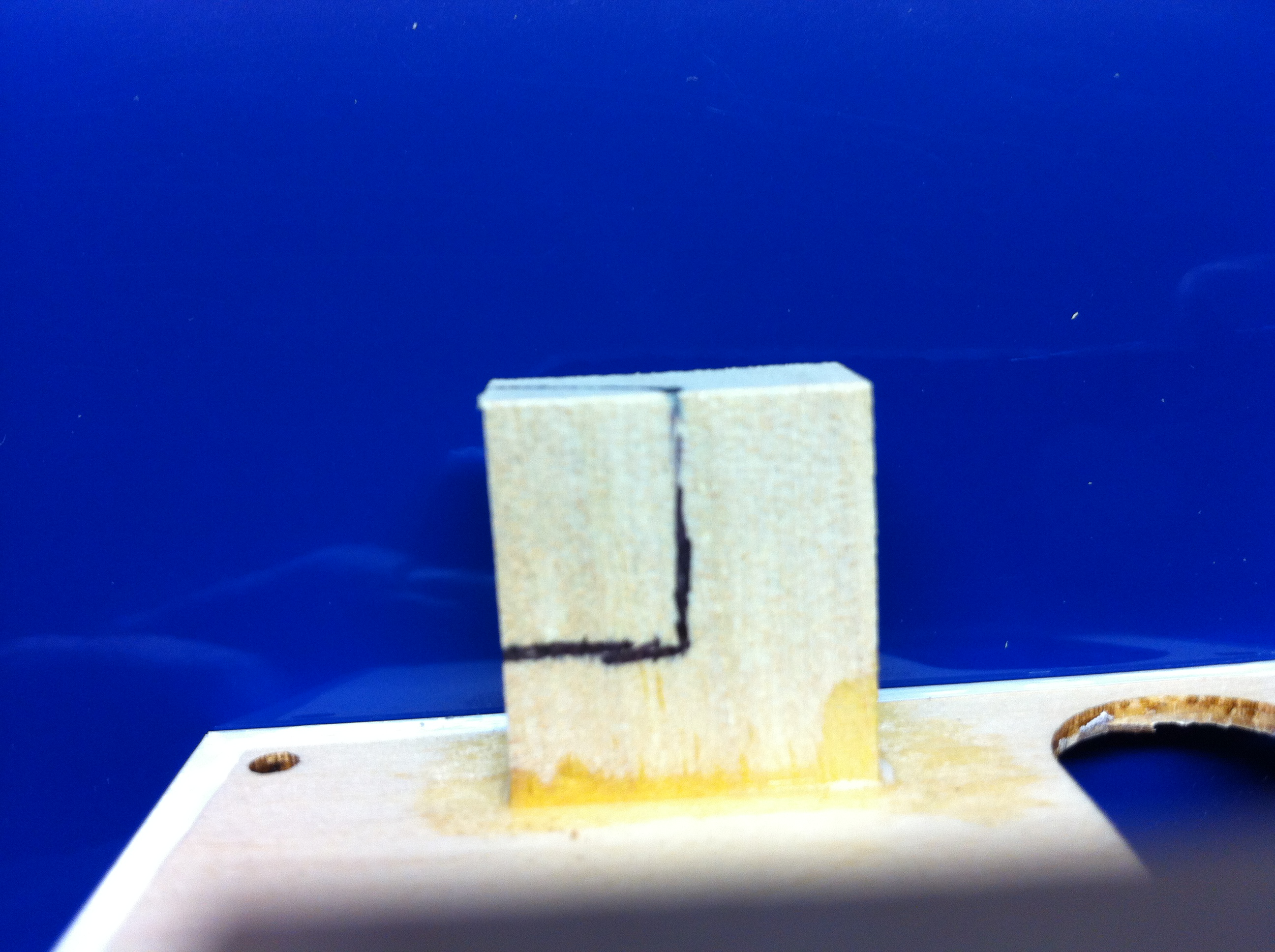
Using a large sanding drum, I removed the material.
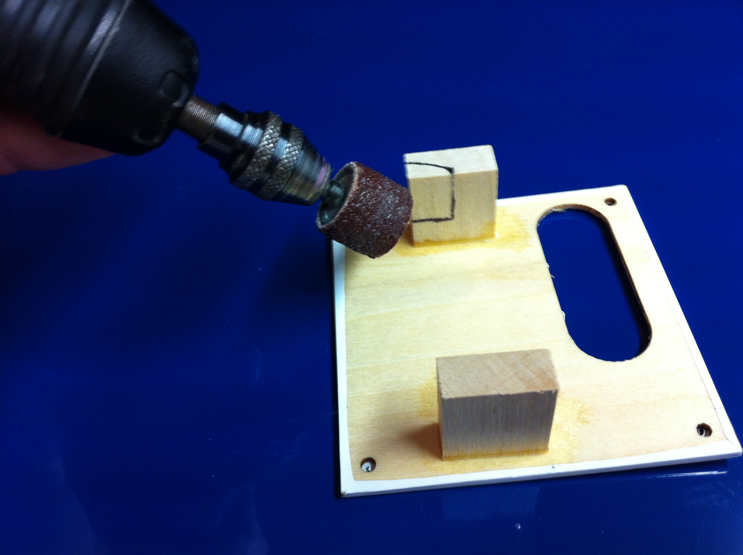

I matched the cutout to the lite-ply and cut it to shape.

Once sanded to fit, I used Medium Zap and a clamp until it dried.

Side note: I have seen this a few times on some planes, even pattern planes. The brass grommets go in from the bottom of the servo so it acts as a stop for the servo screw. If installed from the top it will just dig into the wood until the screw is 'crushed' down to the servo tab.

First thing I did was reverse the covers. This allows for a shorter pushrod.
Then, seeing as there was a wider gap than I am comfortable with for the servo blocks...
I took some scrap 1/8 Lite-Ply and made a filler plate for a block on each cover.
The 9551 servo is a low-profile servo, so the wire was inline with the block. I marked the block to remove some of it.
Using a large sanding drum, I removed the material.
I matched the cutout to the lite-ply and cut it to shape.
Once sanded to fit, I used Medium Zap and a clamp until it dried.
Side note: I have seen this a few times on some planes, even pattern planes. The brass grommets go in from the bottom of the servo so it acts as a stop for the servo screw. If installed from the top it will just dig into the wood until the screw is 'crushed' down to the servo tab.
02-27-2015, 10:24 AM
#36
Thread Starter
My Feedback: (2)
Join Date: May 2002
Location: Around
Posts: 1,432
Likes: 0
Received 0 Likes
on
0 Posts
Next I marked the holes for the servo screws. Again using the #55/.052 drill bit.

And there's always one that's off. Thankfully I didn't drill it when I saw it that far off.

I drilled the ones with the plates at an angle so the screw would go more into the block of wood rather than at the joint of the 2 pieces.

Screwed in.

I used the supplies button head screws and 'pretapped' the hatch plate holes. MAKE SURE to use a machined end (not ball end) .050 wrench. I also put the screw on the wrench before screwing them in (they actually pop on the wrench).

Once all the holes have threads, I use Thin Zap to harden the threads and harden the holes in the cover plates.

Aileron servo leads are next.

I'm not a fan of heatshrinking my leads, so I use masking tape instead. I wrap it around at an angle so the plug can't just come out.


And there's always one that's off. Thankfully I didn't drill it when I saw it that far off.
I drilled the ones with the plates at an angle so the screw would go more into the block of wood rather than at the joint of the 2 pieces.
Screwed in.
I used the supplies button head screws and 'pretapped' the hatch plate holes. MAKE SURE to use a machined end (not ball end) .050 wrench. I also put the screw on the wrench before screwing them in (they actually pop on the wrench).
Once all the holes have threads, I use Thin Zap to harden the threads and harden the holes in the cover plates.
Aileron servo leads are next.
I'm not a fan of heatshrinking my leads, so I use masking tape instead. I wrap it around at an angle so the plug can't just come out.
Last edited by JAS; 02-28-2015 at 08:52 AM.
02-27-2015, 10:32 AM
#37
Thread Starter
My Feedback: (2)
Join Date: May 2002
Location: Around
Posts: 1,432
Likes: 0
Received 0 Likes
on
0 Posts
Control horns are pretty straight forward. Same as the instruction manual.
Since I was using the inner most holes I removed the outer holes. I think this actually saved a gram as well.

I used the horns as the templet and cut (new blade) the covering and removed it so the horn can be glued to the wood.

Scuffed all the horns where they would be inserted into the surfaces.

Same thing on the stabs.

Once the horns and surfaces were ready and everything was test fit, I used Medium Zap and covered the tabs and slid them in. Make sure to carefully clean up and CA that comes up from the horns.

Since I was using the inner most holes I removed the outer holes. I think this actually saved a gram as well.
I used the horns as the templet and cut (new blade) the covering and removed it so the horn can be glued to the wood.
Scuffed all the horns where they would be inserted into the surfaces.
Same thing on the stabs.
Once the horns and surfaces were ready and everything was test fit, I used Medium Zap and covered the tabs and slid them in. Make sure to carefully clean up and CA that comes up from the horns.
02-27-2015, 10:44 AM
#38
Thread Starter
My Feedback: (2)
Join Date: May 2002
Location: Around
Posts: 1,432
Likes: 0
Received 0 Likes
on
0 Posts
Now I aligned the servo arms (radio on). Using the plastic jig I lined up the aileron servo arms.

Then trimmed off the extra arms.

This is how I align my stab servo arms. Slide the stabs on the tube and push them together. With the radio on, rotate the arms until they line up with the ruler from one side to the other. Now you know the servo arms are starting straight to each other. You do not need any sub-trim to do this.

Once you have them aligned, remove the extra arms.


Just for fun I put the links on. Pushrods will be made later.

Yes the elevator pushrods will be at an angle when at neutral. Once the servo moves, the pushrod will become straighter, providing more leverage over a pushrod that starts straight then goes out as the servo rotates. At least that's how it works when I think of it.

Then trimmed off the extra arms.
This is how I align my stab servo arms. Slide the stabs on the tube and push them together. With the radio on, rotate the arms until they line up with the ruler from one side to the other. Now you know the servo arms are starting straight to each other. You do not need any sub-trim to do this.
Once you have them aligned, remove the extra arms.
Just for fun I put the links on. Pushrods will be made later.
Yes the elevator pushrods will be at an angle when at neutral. Once the servo moves, the pushrod will become straighter, providing more leverage over a pushrod that starts straight then goes out as the servo rotates. At least that's how it works when I think of it.
02-27-2015, 10:57 AM
#39
Thread Starter
My Feedback: (2)
Join Date: May 2002
Location: Around
Posts: 1,432
Likes: 0
Received 0 Likes
on
0 Posts
*** THIS IS SOMETHING I DO NOT RECOMMEND DOING AS IT WILL VOID ANY WARRANTY!!!!!
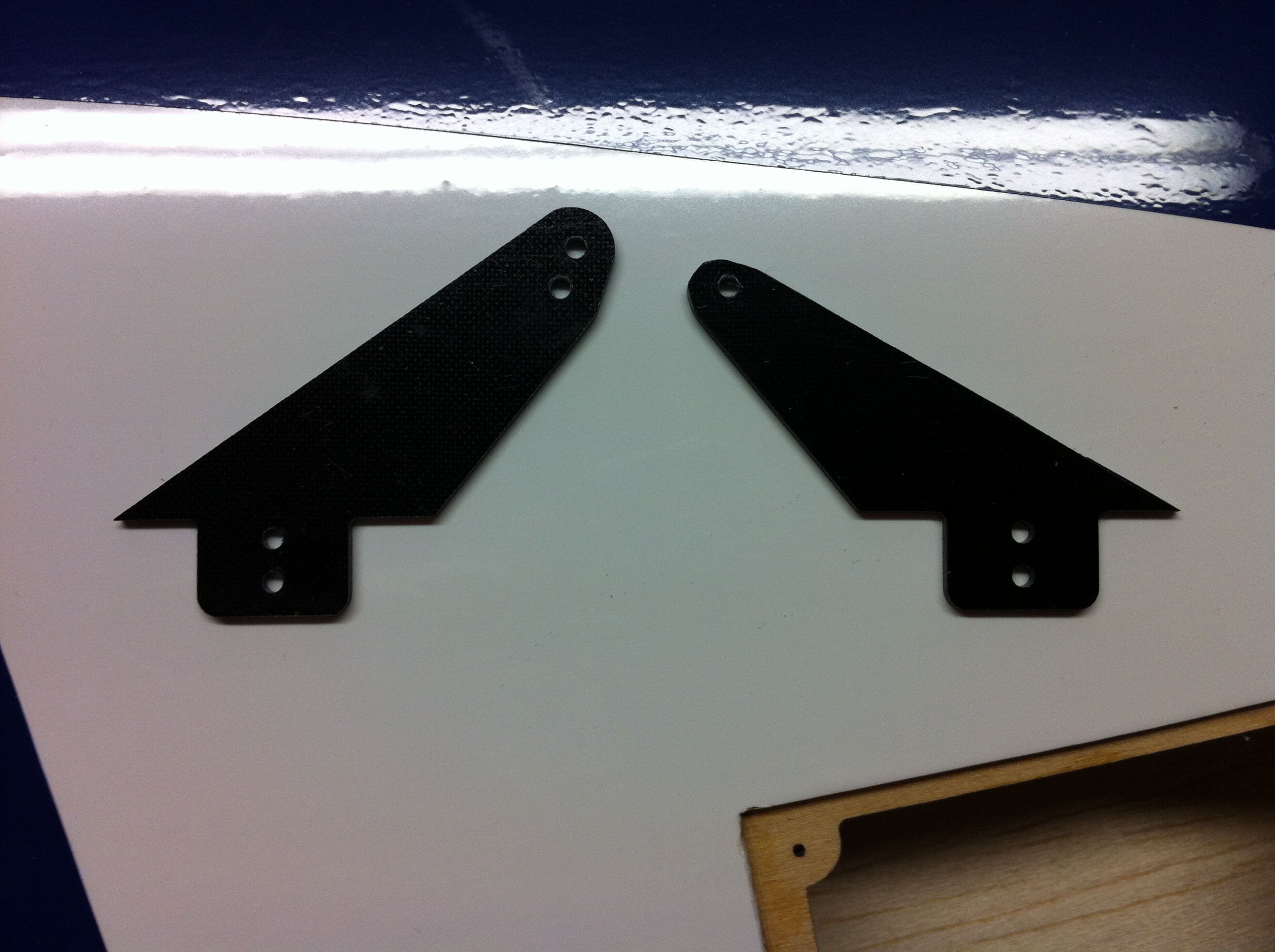
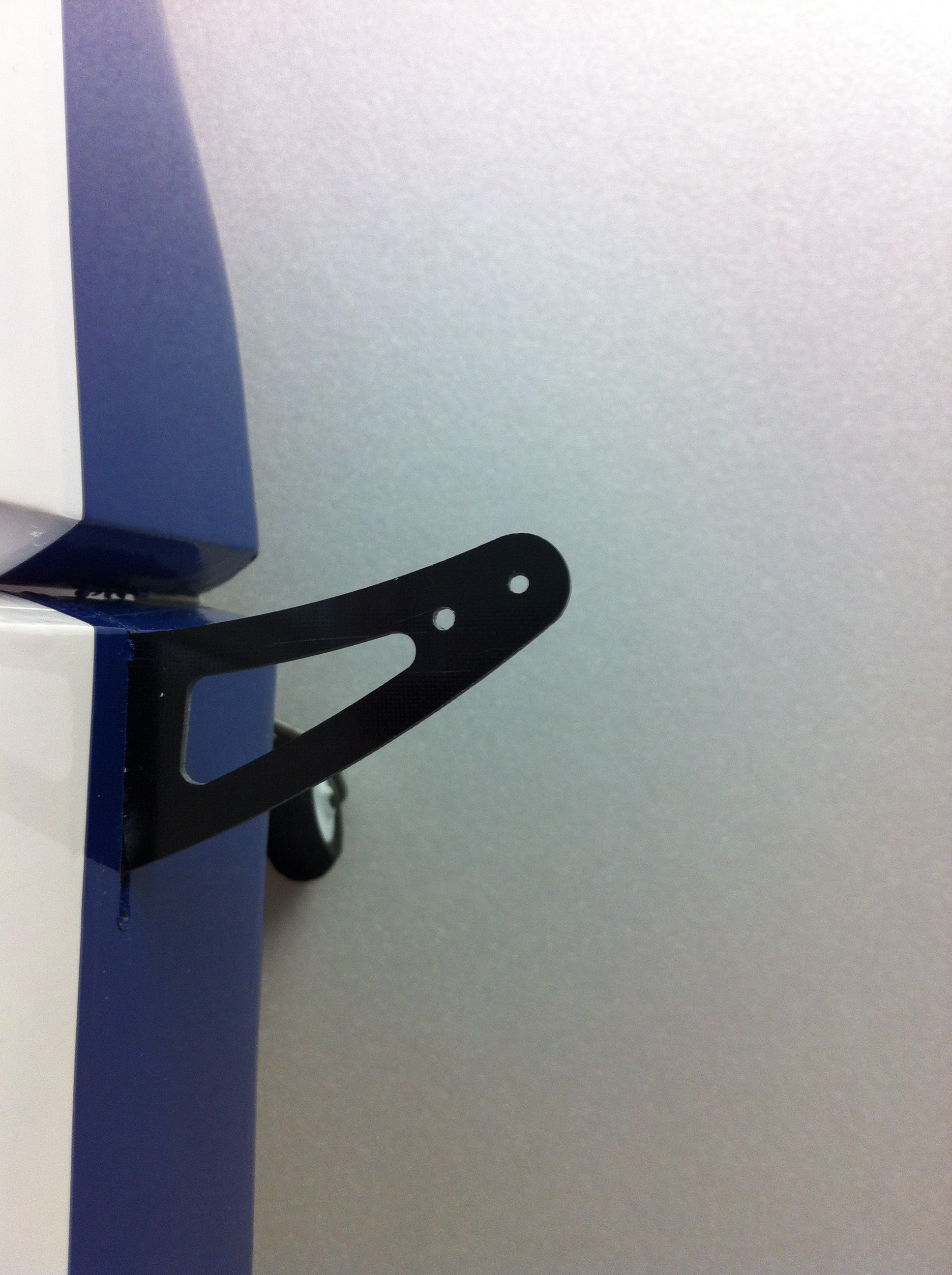
The first thing that jumped out at me when I looked at the fuselage was the broken top cap to the rudder. The second was OMG that rudder horn is huge. Since it was already glued in, I didn't feel like removing it. So thankfully they left enough of the horn not lightened that I could move the hole in a bit. Only bad part is that this would now put my pivot point behind the hingeline. For me, it's not a big deal. As long as my cables are tight at neutral, I'm happy.

First I centered my servo arm. I am not using the recommended metal arm as it weighs 9g. The Du-Bro HD nylon arm I normally use is only 2g.

I marked the current hole and figured out the proper spacing to allow enough material around the new hole.

Once marked, I drilled the new hole using a .82 drill bit.
Then I flipped the tape to the other horn, lining up the stock hole and the LE of the horn to the tap template.

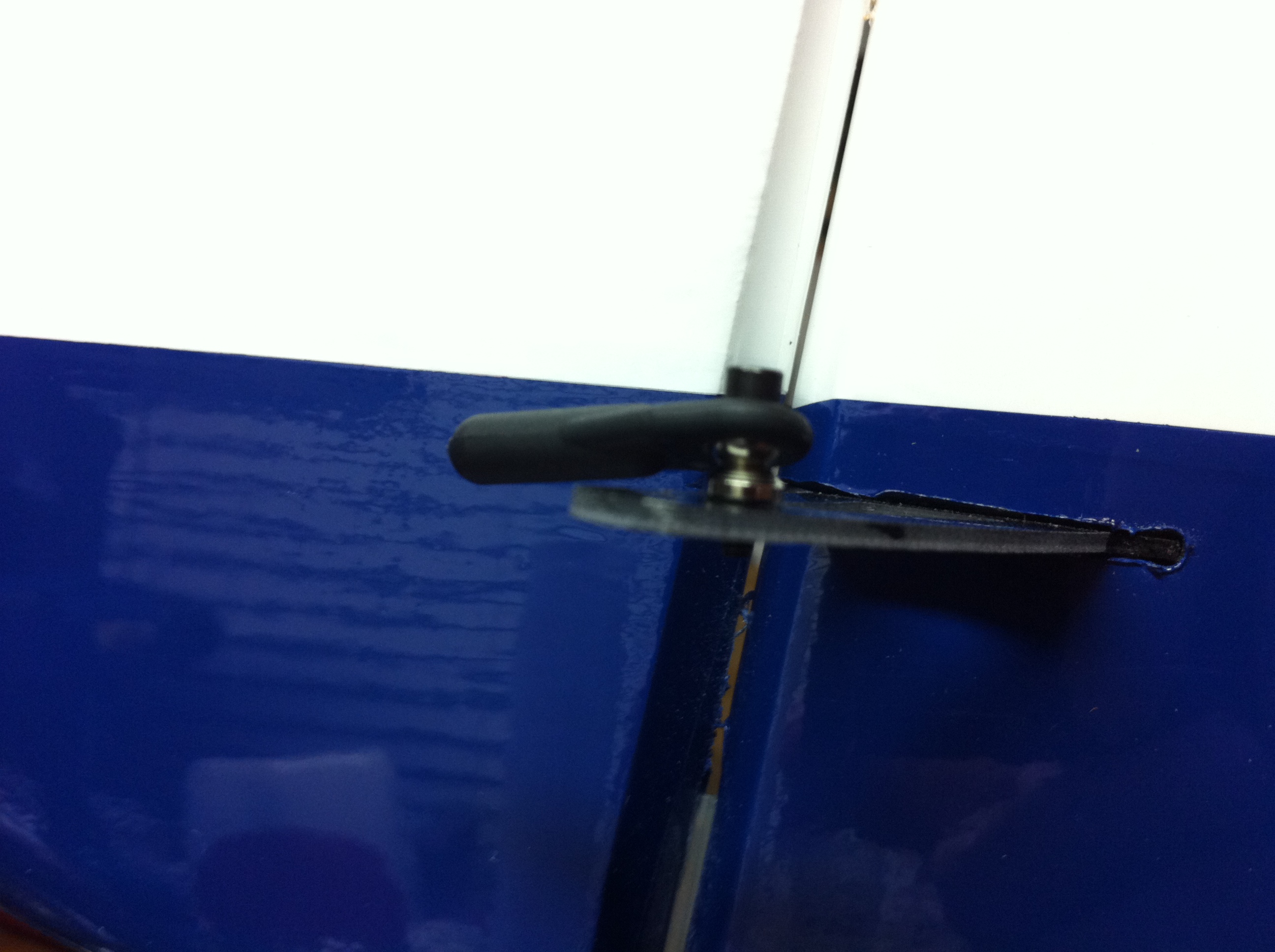
Drilled the second hole and now I have the inner holes. I am not going to remove the extra horn material until after I fly it and see how it works. If it doesn't work, I will use the stock set-up, including the servo arm. (I'll straighten the tailwheel wire out later)
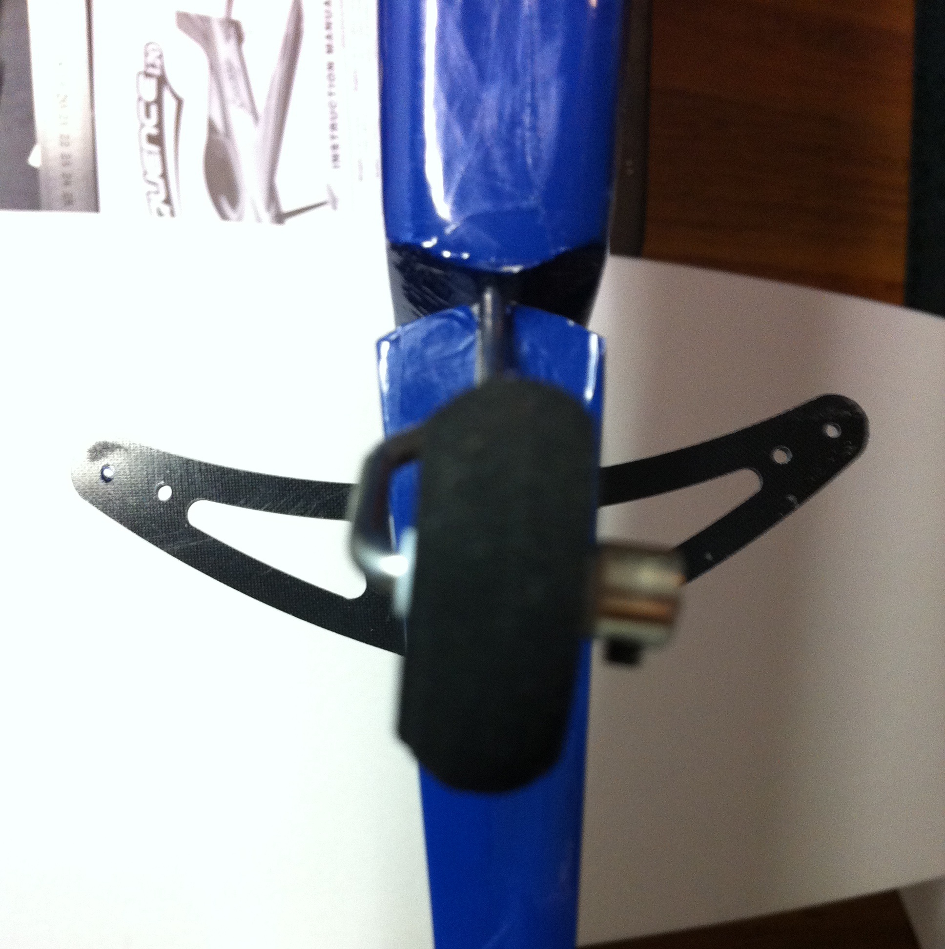
These swivel links will require the standoff's in order to clear the horn.
Using the same .82 drill bit, I drilled out the aileron and elevator horns. (actually did this the step before this)

The first thing that jumped out at me when I looked at the fuselage was the broken top cap to the rudder. The second was OMG that rudder horn is huge. Since it was already glued in, I didn't feel like removing it. So thankfully they left enough of the horn not lightened that I could move the hole in a bit. Only bad part is that this would now put my pivot point behind the hingeline. For me, it's not a big deal. As long as my cables are tight at neutral, I'm happy.
First I centered my servo arm. I am not using the recommended metal arm as it weighs 9g. The Du-Bro HD nylon arm I normally use is only 2g.
I marked the current hole and figured out the proper spacing to allow enough material around the new hole.
Once marked, I drilled the new hole using a .82 drill bit.
Then I flipped the tape to the other horn, lining up the stock hole and the LE of the horn to the tap template.
Drilled the second hole and now I have the inner holes. I am not going to remove the extra horn material until after I fly it and see how it works. If it doesn't work, I will use the stock set-up, including the servo arm. (I'll straighten the tailwheel wire out later)
These swivel links will require the standoff's in order to clear the horn.
Using the same .82 drill bit, I drilled out the aileron and elevator horns. (actually did this the step before this)
Last edited by JAS; 02-27-2015 at 11:19 AM.
02-27-2015, 11:03 AM
#40
Thread Starter
My Feedback: (2)
Join Date: May 2002
Location: Around
Posts: 1,432
Likes: 0
Received 0 Likes
on
0 Posts
Since the weather this weekend isn't supposed to be good, I'll hopefully finish this up and be ready to test fly next week (before FL Jets).
I'll be removing all the lightning/air holes this way. Probably going to add/enlarge others as well.

Not glued, just snapped together. Have to drill the firewall and front mount first.
I'll be removing all the lightning/air holes this way. Probably going to add/enlarge others as well.
Not glued, just snapped together. Have to drill the firewall and front mount first.
02-28-2015, 09:14 AM
#41
Thread Starter
My Feedback: (2)
Join Date: May 2002
Location: Around
Posts: 1,432
Likes: 0
Received 0 Likes
on
0 Posts
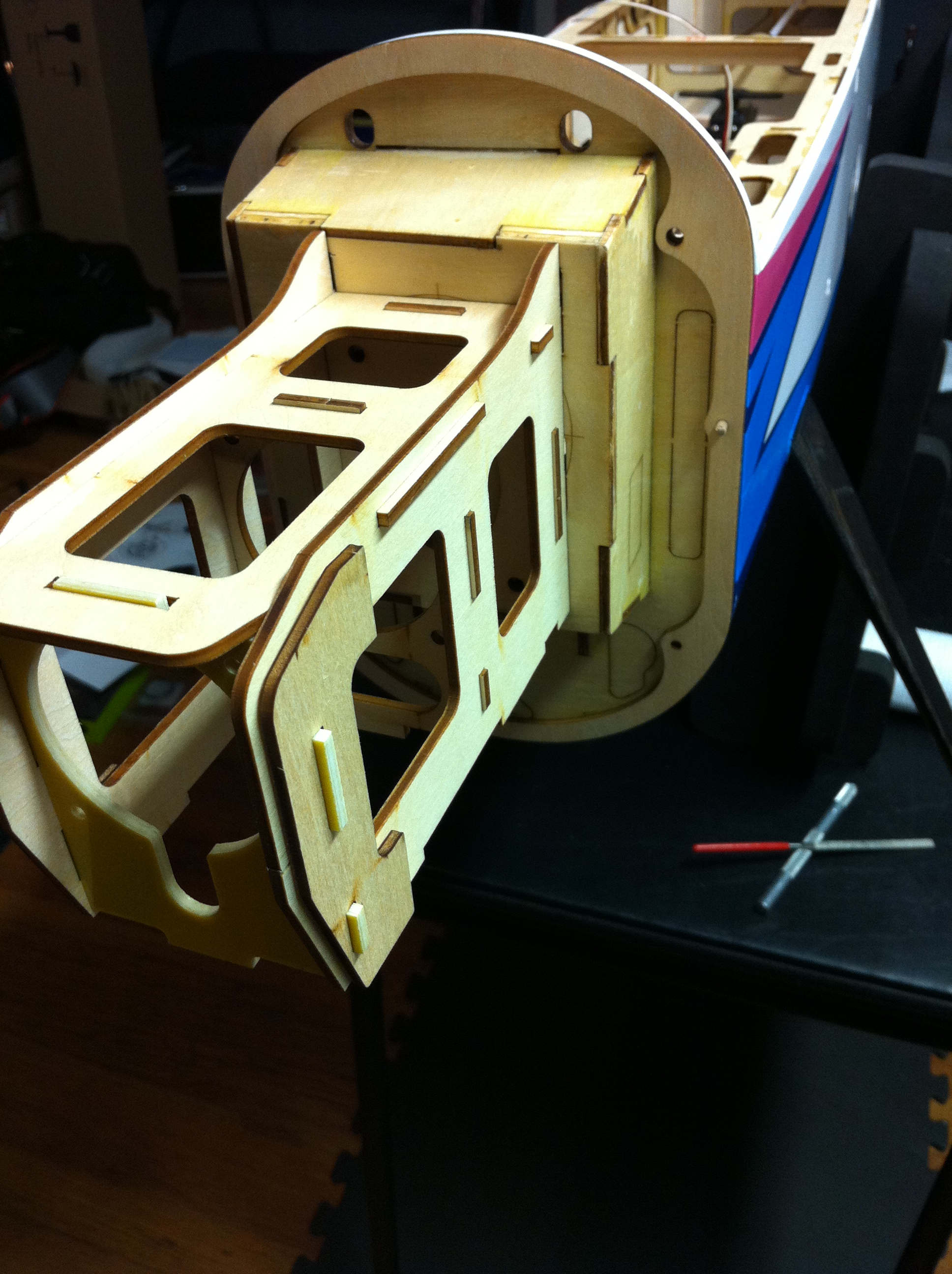
Motor install using the front mount method. This requires the wood motor mount box, which has to be purchased separately. I can see both sides to having to buy this and it being included in the kit. But working at Shulman Aviation, I see first hand that not everyone uses the 'factory set-up' so not including it makes sense to me.
First thing I did was remove the safety collar. A 2mm machine wrench is perfect for this so you don't round out the set screw head. I also found my collar to be stuck and needed a pair of pliers to rotate it free (some thread lock was between the shaft and collar).

Here are the parts, minus the screws, that I would have had to use for a rear mounting set-up.

Here's the part used for this front mounting method. Almost an ounce lighter. I weighed the wood kit and I think it was 126g, but I don't have a metal mount to compare to, but I'm guessing the wood box is lighter. I haven't weighed the re-cut box with carbon parts, but it is lighter.

I used a center punch to mark my centers to drill the 4 mounting holes.
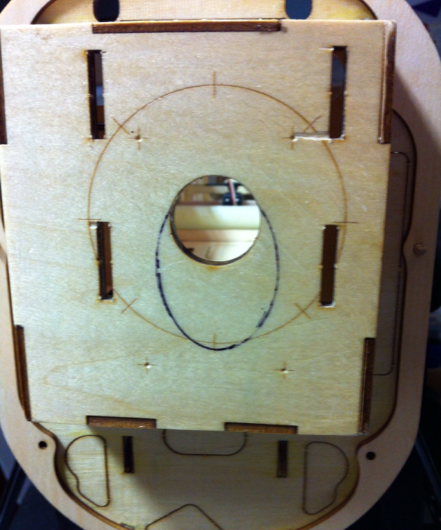
Since I'm looking to save weight everywhere, and work when I can, I noticed that the stock 8/32 blind-nuts were pretty big. I think I would have had to trim some of the flanges so they wouldn't interfere with the mount sliding in the firewall, so I opted for the smaller, lighter Du-Bro 8/32 blind-nuts. This saved 4g if I remember correctly.

Using a .221 drill bit, I drilled the 4 holes. If you're using the stock blind-nuts, use a .202 drill bit.

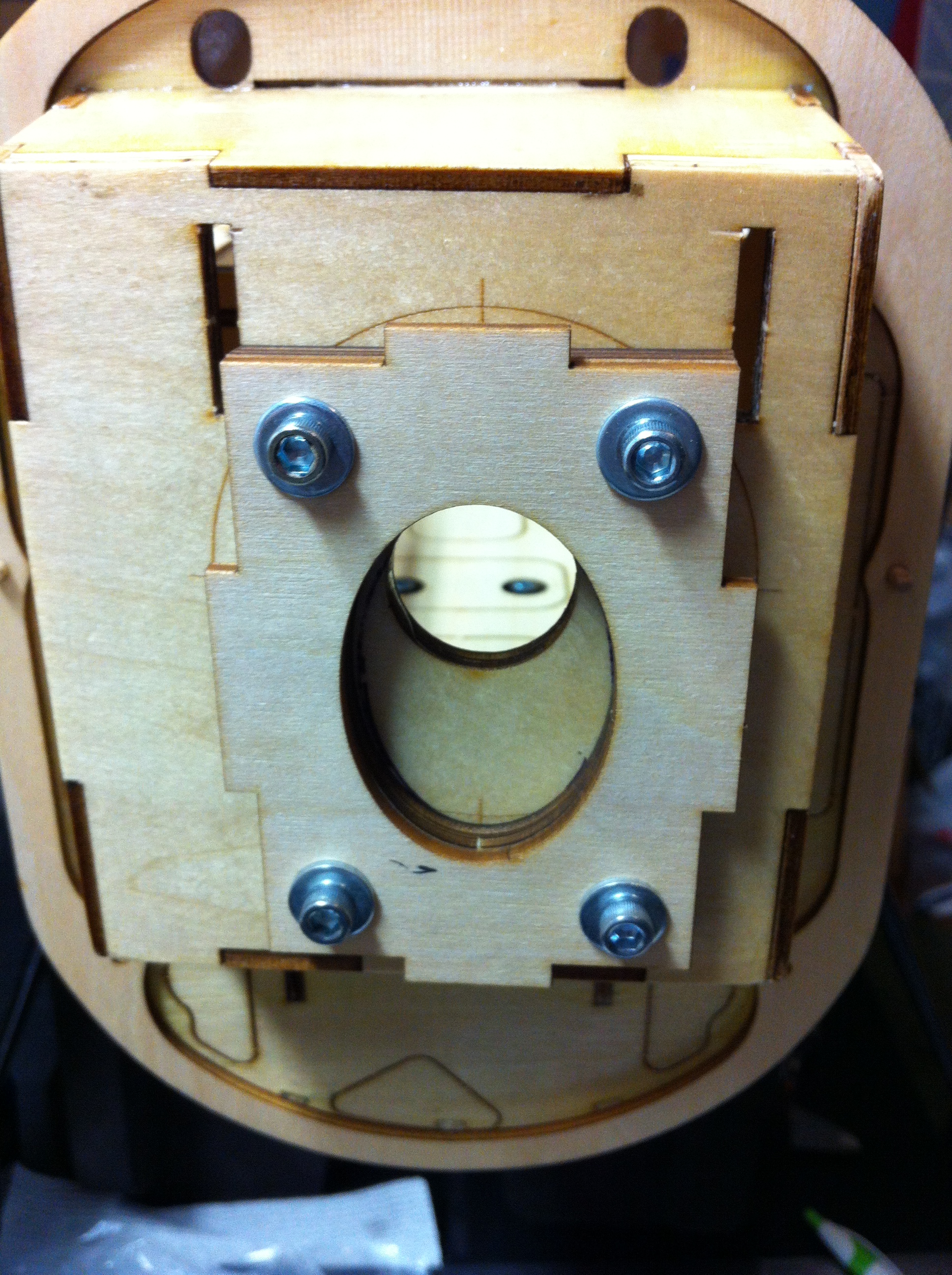
Then with the supplied 8/32 screws and flat washers, I pulled the blind-nuts into the firewall.

Double checked it with the plywood rear mounts to make sure everything lined up well, and it did.

First thing I did was remove the safety collar. A 2mm machine wrench is perfect for this so you don't round out the set screw head. I also found my collar to be stuck and needed a pair of pliers to rotate it free (some thread lock was between the shaft and collar).
Here are the parts, minus the screws, that I would have had to use for a rear mounting set-up.
Here's the part used for this front mounting method. Almost an ounce lighter. I weighed the wood kit and I think it was 126g, but I don't have a metal mount to compare to, but I'm guessing the wood box is lighter. I haven't weighed the re-cut box with carbon parts, but it is lighter.
I used a center punch to mark my centers to drill the 4 mounting holes.
Since I'm looking to save weight everywhere, and work when I can, I noticed that the stock 8/32 blind-nuts were pretty big. I think I would have had to trim some of the flanges so they wouldn't interfere with the mount sliding in the firewall, so I opted for the smaller, lighter Du-Bro 8/32 blind-nuts. This saved 4g if I remember correctly.
Using a .221 drill bit, I drilled the 4 holes. If you're using the stock blind-nuts, use a .202 drill bit.
Then with the supplied 8/32 screws and flat washers, I pulled the blind-nuts into the firewall.
Double checked it with the plywood rear mounts to make sure everything lined up well, and it did.
Last edited by JAS; 03-02-2015 at 11:33 AM.
02-28-2015, 10:10 AM
#42
Thread Starter
My Feedback: (2)
Join Date: May 2002
Location: Around
Posts: 1,432
Likes: 0
Received 0 Likes
on
0 Posts
*** The mount that I mocked up a couple of posts ago is the stock, Tower mount. The mount that I am using is basically the same, but has carbon plates instead of the fiberglass plates. Thanks Tim.
I glued the 3 rear mounting plates together and bolted them to the firewall as a clamp. If I had to do over, I would have just put the 4- 8/32 screws in to align it and used clamps.
Then I glued the rear mount to the top and one side (right in this case).

Then I glued in a side piece of 2" tristock. Dry fit this first and make sure the rear bolts/washers will clear the corners.

Then I glued in the middle former.

Make sure that you have the double for the front (without tabs) glued to the front Fiberglass piece, then install it.

Glue in the top 1" Tristock before putting on the other side of the box. Then glue on the other side of the box.

I didn't get to the bottom last night, but I did put the motor on just for fun to see it with the cowling on.


Should have the motor and cowl done tonight, then pushrods and wheels/pants.
I glued the 3 rear mounting plates together and bolted them to the firewall as a clamp. If I had to do over, I would have just put the 4- 8/32 screws in to align it and used clamps.
Then I glued the rear mount to the top and one side (right in this case).
Then I glued in a side piece of 2" tristock. Dry fit this first and make sure the rear bolts/washers will clear the corners.
Then I glued in the middle former.
Make sure that you have the double for the front (without tabs) glued to the front Fiberglass piece, then install it.
Glue in the top 1" Tristock before putting on the other side of the box. Then glue on the other side of the box.
I didn't get to the bottom last night, but I did put the motor on just for fun to see it with the cowling on.
Should have the motor and cowl done tonight, then pushrods and wheels/pants.
03-01-2015, 06:02 AM
#43
My Feedback: (21)
Join Date: Aug 2009
Location: Apple River IL
Posts: 951
Likes: 0
Received 0 Likes
on
0 Posts
Great tips and pics JAS. I'll try to post a pic of the collet/motor misalignment later (but I'm out of town until 3/23). I'm going to use the wood box (thanks Tim) and front mount the 1.20 also so I guess it's a moot point unless I used this setup in another plane. Ordered and received the other collet needed for the front mount already too. I did the pushrods per your method and they came very well, really like that method so I plan to use it on my classic pattern planes as well. Appreciate the pics and tips here JAS.
Mark
Mark
Last edited by hook57; 03-01-2015 at 06:08 AM.
03-01-2015, 07:59 PM
#44
My Feedback: (18)
Join Date: Jan 2003
Location: Florida
Posts: 108
Likes: 0
Received 0 Likes
on
0 Posts
Using the plastic jig, factory supplied , in the manual it states-use the plastic servo arm gauge to find the servo arms that will align with the gauge as shown. (This will allow the servo arm to be perpendicular to the pushrods.)
To me it looks like they are having you use Aileron differential, and just not telling you.
To me it looks like they are having you use Aileron differential, and just not telling you.
Last edited by rampage-1; 03-01-2015 at 08:02 PM.
03-02-2015, 11:06 AM
#45
Senior Member

In reference to the weights of the optional wood motor mount and collet prop adapter vs. the aluminum motor mount, X-mount for the motor, collar and bolt-on adapter; I just weighed a Great Planes Brushless Mount for Large Motors (GPMG1260) I snagged out of our back storage room and it weighs 126g [4.4 oz.]. If, as Jason says the wood mount weighs 96g, that's a difference of 30g [about an ounce].
FYI...
Tim
P.S. I plan to use a Castle Creations Edge Lite 100 ESC on my Sequence 1.20. I can't see anything wrong with using that, can any of you guys? Not sure if I'll use a separate 2S LiFe receiver pack (unregulated), or just to with the BEC in the ESC for Rx power. Will some of you pattern experts offer your opinions/suggestions on these two options. Obviously, foregoing an Rx pack will reduce weight, but if the ESC smokes that's bad! But what are the chances of smoking that ESC in my setup (stock Rimfire 1.20 on 6S).
Thanks.
Tim
03-02-2015, 11:47 AM
#46
Thread Starter
My Feedback: (2)
Join Date: May 2002
Location: Around
Posts: 1,432
Likes: 0
Received 0 Likes
on
0 Posts
Mark,
Glad to hear that the linkages worked out for you. I don't know how the CA will hold up under fuel, so you might want to use JB Weld instead (assuming your Classic is glow powered).
Ramp,
It could also be what they found during testing was that this setting made the plane roll straight. I will do a test with some wire and see if the stock set-up gives any differential. I usually fly with 1-2mm more up than down anyway, so if it turns out close to that I'll leave it and adjust in the radio if needed.
Tim,
I weighed the stock mount when I got home Sunday and found it at 126g also. I will reweigh the new mount before bolting it in. As for using the ESC BEC, I think on a plane of this size, you should run a separate battery and switch. This is a lot of plane to hope that the BEC holds up. I know it's extra weight, but it's also (for me at least) a piece of mind to have a separate Rx battery, and a small (730ish mah) lipo and regulator (or LiFe without a regulator) doesn't weigh too much.
It's not looking good to have it flying before FL Jets, so It'll probably be next week before it's flown. I did notice that my cowling frame (for the 'hidden' screws) is about a 64th more narrow than my fuselage, so I will have to build it out a bit to clear the fuse. Not a biggie, just unforeseen. I debated about just screwing the cowl to the fuse the easy way... but it's a pattern plane, so I'll do it 'right'
03-03-2015, 10:31 AM
#47
My Feedback: (21)
Join Date: Aug 2009
Location: Apple River IL
Posts: 951
Likes: 0
Received 0 Likes
on
0 Posts
Good point re the glow fuel on the classics JAS, I'll watch that, maybe test it first. The cowl ring on mine was a tad oversized, I sanded it to be flush and it fits quite nicely now. However, no way could I line up the trim colors on both sides, might put some silver/gold stripes there to minimize it.
Thanks for the weight info Tim. I think I prefer the front mounting with the wood motor box so I'll be setting mine up that way.
Mark
Thanks for the weight info Tim. I think I prefer the front mounting with the wood motor box so I'll be setting mine up that way.
Mark
03-04-2015, 12:20 PM
#48
Senior Member
Tim,
...As for using the ESC BEC, I think on a plane of this size, you should run a separate battery and switch. This is a lot of plane to hope that the BEC holds up. I know it's extra weight, but it's also (for me at least) a piece of mind to have a separate Rx battery, and a small (730ish mah) lipo and regulator (or LiFe without a regulator) doesn't weigh too much.
Thanks for your recommendation to use a separate Rx pack rather than rely upon the BEC in the ESC for powering the radio. I fully understand the reasons why. But I wonder about this...what about a separate Castle Creations BEC/regulator off the 6S motor battery for powering the Rx and servos? Sure, one more thing to possibly fail (should the BEC conk out).
I'm just picking your brain to find out what is the consensus (if there even is one) among Pattern guys.
Thanks again for your opinions (or anybody else who wants to offer theirs!).

Tim
03-05-2015, 08:53 AM
#49

A lot of us run separate receiver packs with a regulator. Obviously you get the ability to control the plane if the power battery or connections fail. You also get consistent potential (voltage) at every servo for every flight - there is no trail off of servo speed or servo power. I remember how much I enjoyed my first few flights with a regulator.
Some guys have gone to different lithium battery technology and/or HV servos to eliminate the failure point of the regulator. There you lose the voltage consistency but I really don't know what the drop off looks like for a LiFe battery or something like that - maybe it's not so bad.
Others have run regulators off the Ground and #2 cell balance wires from the motor battery. I think this is often done in tandem with a small reserve battery as the balance leads are known to fail, at least on the less expensive imported batteries.
It seems like BEC would give you consistent servo power, but really I don't know what the regulated power looks like. It should be at least somewhat consistent, but it could also fluctuate based on demand and remaining capacity.
There is no right or wrong answer, you do what makes you comfortable. I run two small batteries and two small regulators in the plane(s) I care the most about. I had 1 battery and reg in my 1.20 but would have liked 2, that plane is gone and the replacement is almost certainly going to have 2 packs. I have a little 15e Bonanza that I might eventually put together. I planned on running BEC but when the time comes I expect I'll reconsider that decision.
I don't know how much safety you get of having 1 external pack with a reg vs using BEC power - either way, it only takes one bad connection to lose power. It seems like the receiver packs are less likely to have issues but that's not based on any data, other than typical power demand. I guess it seems easier to run a power pack down below serviceable limits (I guess that is changing with telemetry), but its also easy to squeeze one too many flights out of an Rx pack if it is small. My packs (480mah) are enough for a normal day of flying. Probably not enough for an all-day event at a quiet field, but that has been rare since college where I could blow of class and go burn fuel.
Here is a pic of my 'heavy' reg and battery on the scale (44.5g):
Last edited by Jetdesign; 03-05-2015 at 09:04 AM.
04-03-2015, 07:13 AM
#50
Senior Member
Getting close to finishing my Sequence 1.20.
But I ordered a carbon tail tube and wing tube from Graph Tech a while ago. I inquired about the order with an email via their contact information on their site, but no reply. I also telephoned them, but a message says the number is disconnected. Anybody deal with Graph Tech much and heard anything?
Thanks.
Tim
Edit: Cool. One of my orders showed up with my CF tail tube. Hopefully the other with the wing tube won't be far behind.
Edit again!: 'Nother package showed up at my doorstep today...the large wing tube I ordered from Graph Tech! Fits PERFECT too, just need to cut it down. Kinda annoying not to be able to be able to contact the company, but they did come through with my tubes! It's all good!
Last edited by krproton; 04-06-2015 at 04:42 PM.