


Amadeus


 07-25-2016, 08:14 PM
#128

Thread Starter
I've glued the stiffener into one half using scraps of balsa cynoed in to hold it in position while the epoxy microballoon mix (5.5gm) goes off. Normally I would be considering lightening it but the latest Allures have stopped lightening them. Maybe to eliminate extra cross ribs or for extra stiffness. I have never used a rear fuselage stiffener so I thought I would take their lead and see how it pans out. Will probably do another fuselage now I have worked out a system for them.

07-27-2016, 06:20 PM
#129
Senior Member
Rodney,
I have been posting in only one thread in the electric column and have not paid a lot of attention elsewhere. Glad I stopped here to read a little of your thread. Nice work and good luck with the flying.
I have been posting in only one thread in the electric column and have not paid a lot of attention elsewhere. Glad I stopped here to read a little of your thread. Nice work and good luck with the flying.
07-27-2016, 06:49 PM
#130
Thread Starter
Finally got one out of the mold. Very happy with the weight, however there are a few blemishes and a few things I would like to do differently. So I think I will do another one.


07-27-2016, 08:20 PM
#131
Senior Member
You may want to add some more glass around the wing TE and 6" aft. Also, a bit more around the stab LE.
I had one buckle just aft of the wing TE. Just not enough reinforcement.
Weight wise you have plenty of room for the extra 20 grams.
I had one buckle just aft of the wing TE. Just not enough reinforcement.
Weight wise you have plenty of room for the extra 20 grams.
07-28-2016, 12:50 AM
#132
Thread Starter
Sounds like you know what you are talking about. Did you take into account the 6mm Depron stiffener I put in? I've never used one and it has adding a lot of strength. I will be adding carbon around the wing and stab tubes.
07-28-2016, 02:04 AM
#133
Hi Rodney,
You may want to do another but that is some start - very good weight.
The brace across the rear half will do a lot to retain integrity. It keeps every thing in place which will help avoid compression failures.
Matt, Did yours delaminate or just break - or was it too crash damaged to know ?
Brian
You may want to do another but that is some start - very good weight.
The brace across the rear half will do a lot to retain integrity. It keeps every thing in place which will help avoid compression failures.
Matt, Did yours delaminate or just break - or was it too crash damaged to know ?
Brian
Last edited by serious power; 07-28-2016 at 02:09 AM.
07-28-2016, 02:58 AM
#134
Hi Rodney,
Just noticed something now, sorry !
Have you had to join the Rohacell core ?
I would taper/splice or use a finger (zig-zag/saw tooth) joint so as to avoid stress focusing !
Brian
Just noticed something now, sorry !
Have you had to join the Rohacell core ?
I would taper/splice or use a finger (zig-zag/saw tooth) joint so as to avoid stress focusing !
Brian
Last edited by serious power; 07-28-2016 at 05:07 AM.
07-28-2016, 08:06 AM
#135
Senior Member
Hi Rodney,
You may want to do another but that is some start - very good weight.
The brace across the rear half will do a lot to retain integrity. It keeps every thing in place which will help avoid compression failures.
Matt, Did yours delaminate or just break - or was it too crash damaged to know ?
Brian
You may want to do another but that is some start - very good weight.
The brace across the rear half will do a lot to retain integrity. It keeps every thing in place which will help avoid compression failures.
Matt, Did yours delaminate or just break - or was it too crash damaged to know ?
Brian
I didn't think to take a good look aft of the pipe tunnel. I saw the foam crutch in the rear section and thought all was okay. In retrospect, the foam was not glassed and offered marginal strength. A built up crutch from balsa sticks probably would have proved stronger and could have been lighter.
The snaps and wind appeared to cause the fuse buckle at the wing TE. The crutch started about 4" to the rear of this area and just wasn't there to support things. Anyway I managed to quasi control the model into 2 foot tall soy beans but the resulting hard landing finished the fuse off. Post mortem revealed rather scant glass on the inside which was at most 1 ounce cloth. Had I realized, I would have added one more layer of 1.5 ounce in this weak area.
Hence the suggestion to Rodney to beef up the area aft of the wing TE. One layer of 25 gram glass may not be enough. The Griffin fuse was pretty large and I can't tell if Rodney's fuse is of similar size.
I know the Griffins suffered from bad wings early on but that problem was fixed. My fuse appears to have been the only one to have suffered this fate. Just unlucky I guess. But as I said elsewhere, little emotional attachment here. If it was my lay up, it would not have been built that way.
I discussed the experience with Bryan Hebert along with the landing gear mods. The factory was apparently thrilled with the gear mods.....easy to implement saving a bunch of weight. We'll see when these will show up in Bryan's offerings.
07-28-2016, 09:07 AM
#137
Senior Member
The total weight of the mount in the fuse is about 20 grams. My complete, rtf weight of the gear is just under 5 ounces with spats. So about 5 1/2 ounces installed and rtf.
I make struts and spats sets in my own molds. Aligned in the mold, these are highly engineered units that are exceedingly strong since I fly from rough grass airfield. Not any spat will do. So factory execution will wait to be seen since attention to detail is critical....
Last edited by MTK; 07-28-2016 at 09:23 AM.
07-28-2016, 10:13 AM
#138
Thread Starter
Rod
07-28-2016, 11:34 AM
#139
Hi,
From one of Matts threads ;
http://www.rcuniverse.com/forum/rc-p...new-2x2-5.html
He may have moved on from this but I think this is great. The Wistmodel system involves a moulding that fits into the fuz,, that the gear then slots into.
Brian
From one of Matts threads ;
http://www.rcuniverse.com/forum/rc-p...new-2x2-5.html
He may have moved on from this but I think this is great. The Wistmodel system involves a moulding that fits into the fuz,, that the gear then slots into.
Brian
Last edited by serious power; 07-28-2016 at 12:16 PM. Reason: typo
07-28-2016, 12:02 PM
#140
Senior Member
Hi,
From one of Matts threads ;
http://www.rcuniverse.com/forum/rc-p...new-2x2-5.html
He may have moved on from this but I think this is great. The Wistmodel system involves a melding that fits into the fuz,, that the gear then slots into.
Brian
From one of Matts threads ;
http://www.rcuniverse.com/forum/rc-p...new-2x2-5.html
He may have moved on from this but I think this is great. The Wistmodel system involves a melding that fits into the fuz,, that the gear then slots into.
Brian
Rodney, the gear struts are rather slender and thin by most standards. They are shock absorbing to reduce load transfer to the fuse. These are designed such that they are neutral....no front or back to them. The tangs insert into sockets self aligning. A single 4-40 screw holds each in place.
A 21/2" square carbon cloth is epoxied on bias in the fuse sides. The carbon and aircraft plywood sockets are installed into the carbon cloth, through each side of the fuse, with some laminating epoxy filled with micro balloons and carbon chop. The struts are then put into their final location, bolted in place and the epoxy is then cured with everything aligned.
Highly recommend this mounting method with the shock absorbing struts. It has proven itself super reliable over the past 4 or 5 airplanes and at least 1500 flights. With your skill, it should t be that tuff to figure out the details, but if you get stuck, shoot me off a pm.
spat treatment is another subject we can discuss if you like. It is different, lighter and more secure than anything flying today in pattern.
Last edited by MTK; 07-28-2016 at 12:06 PM.
07-28-2016, 12:33 PM
#141
Thread Starter
Hi,
From one of Matts threads ;
http://www.rcuniverse.com/forum/rc-p...new-2x2-5.html
He may have moved on from this but I think this is great. The Wistmodel system involves a moulding that fits into the fuz,, that the gear then slots into.
Brian
From one of Matts threads ;
http://www.rcuniverse.com/forum/rc-p...new-2x2-5.html
He may have moved on from this but I think this is great. The Wistmodel system involves a moulding that fits into the fuz,, that the gear then slots into.
Brian
Thanks for that Brian. I had got halfway through Matt's 40 pages of posts and still hadn't found it. Course I was waylayed quite a few times. I too have found soft gear mounts to be beneficial to airframe longevity so I always rubber mount them. I really like his system but would make it softer still. Maybe just a short length of cycle inner tube around the leg as it passes through the fuselage wall.
Rod
07-28-2016, 01:02 PM
#142
Rodney,

That's exactly what I'm doing with mine.
Will get back to it in a couple of months - trying to finish up a house renovation as we speak.
Matt has a lot of stuff well worked out.
These materials, Rohacell etc, are expensive when it comes to trial lay-ups. We used to make up 100mm x 100mm test pieces.
A former or A frame set into the rear of the canopy opening may be worth a thought also.
Brian
07-28-2016, 01:04 PM
#143
Thread Starter
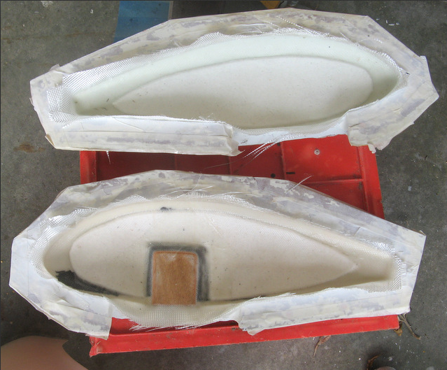
Well Matt I am very interested to hear what you have to say regarding spats. This is how I make my legs and will be easy to adapt to your style of leg. The mold is cut from blue foam with my cnc foam cutter then lined with mylar then dams inserted to shape the legs. 13 layers uni 3 layers bias cloth 78gm.


07-28-2016, 01:40 PM
#144
Thread Starter
Matt here are a few shots of my Slick 360 (DA200) spats. The idea is to have 2 inserts to mold recesses for the legs. This means I can mold left and right spats out of one mold.
 Making inserts.
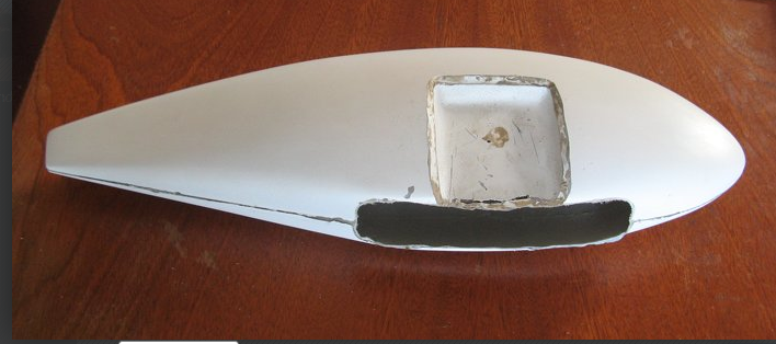

Not sure yet if this will work on my little F3A spat molds.
Not sure yet if this will work on my little F3A spat molds.
07-28-2016, 01:50 PM
#145
Thread Starter
Brian yes the Rohacell is expensive. We get from Clarisonic in Thailand so there is freight too. I am thinking of making a fuselage with extruded polystyrene instead. I can cut sheets of it really nicely with the CNC cutter to any thickness. I have some .2oz carbon tissue which I would use inside the 50gm glass to harden the surface.
07-28-2016, 02:40 PM
#146
Senior Member
I usually use two layers of 2 ounce cloth for the smaller. Then add carbon cloth to both sides of the spat in the axle area. Then I add the steel nuts to both sides that the axle screw goes through and secure it with some glass and carbon chop.
My molds have alignment tubes at the nut areas such that the 8-32 screw pulls the nuts into perfect alignment.
Once the spat halves have joined, I add carbon roving around the wheel hole. The spattypically weighs 12-13 grams after all of the reinforcements and nut install. The spat and strut are epoxied together with high strength flex epoxy.
The axle is of course an 8-32 bolt about 11/2" long. The steel secures both sides of the spat
Ill take a photo of a complete strut and post.
07-28-2016, 03:00 PM
#147
Hi,
Some material weights that may be of interest.
Nothing new here but we forget or forget to compare.
Contest grade balsa ; 80Kg/m\3. I would estimate the balsa used in those RR models in the other thread is at around 120Kg/m\3 and some a bit heavier maybe at 135Kg/m\3
Airex in Todds lay up ; 80Kg/m\3 He used C70.75 I can't find Herex per say. The C70 is available at 40, 48,60 & 80Kg, but getting it in thin sheets (<5mm) seems to be a problem at the lower densities.
Nomex ; 24, 29, 40, 48, 64, & 80Kg/m\3 etc It is available at a range of cell sizes both std and over-expanded (more flexable)
Rohacell ; 32, 52 & 75Kg/m\3
http://www.airexbaltekbanova.com/air...-pvc-foam.html
Link to data sheet down the page
http://www.cacomposites.com/nomex-ho...fkUaApXh8P8HAQ
http://www.rohacell.com/sites/lists/...perties-EN.pdf
Brian
Last edited by serious power; 07-28-2016 at 03:03 PM.
07-28-2016, 03:50 PM
#148
Thread Starter
Hi Matt would like to see some pics thank you. Another option I am thinking about is using my 3D printer to make spats (and spinners). I'm currently upgrading my printer so I can use some of the more exotic materials that are coming out.
Brian thanks for those specs. Standard extruded poly is 32Kg/M3 and I also have some 38Kg/M3. This cuts really smoothly and due to the radiant heat cutting method leaves a bit of a hard surface. I have been using 52Kg/M3 Rohacell so it will have better impact/dent resistance. Hence thinking about carbon tissue.
Rod
07-29-2016, 11:20 AM
#149
Senior Member
I'm having a heck of time posting from the phone....one more time

Well used spat mold....I need to build another. Shows the axle bolt areas
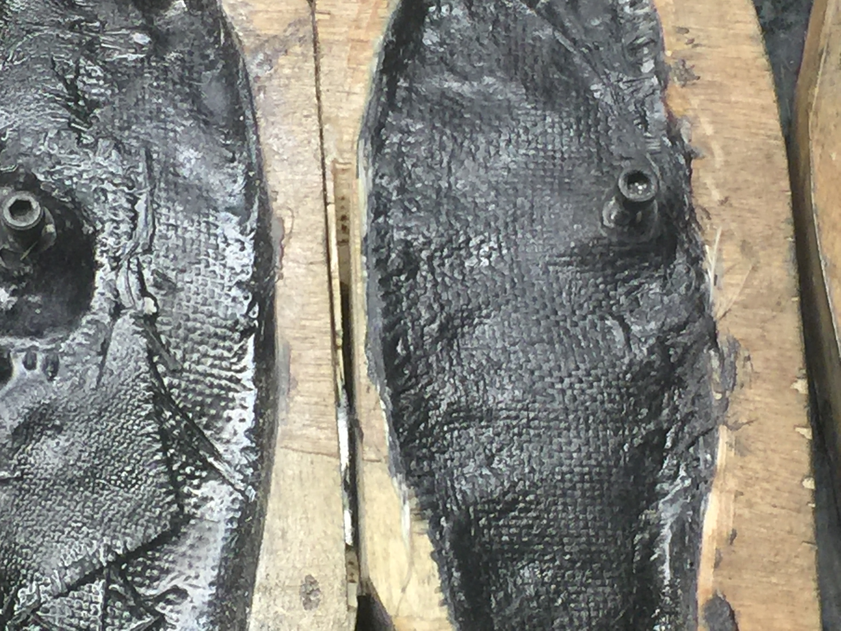
Outside view of mold showing the alignment tubes
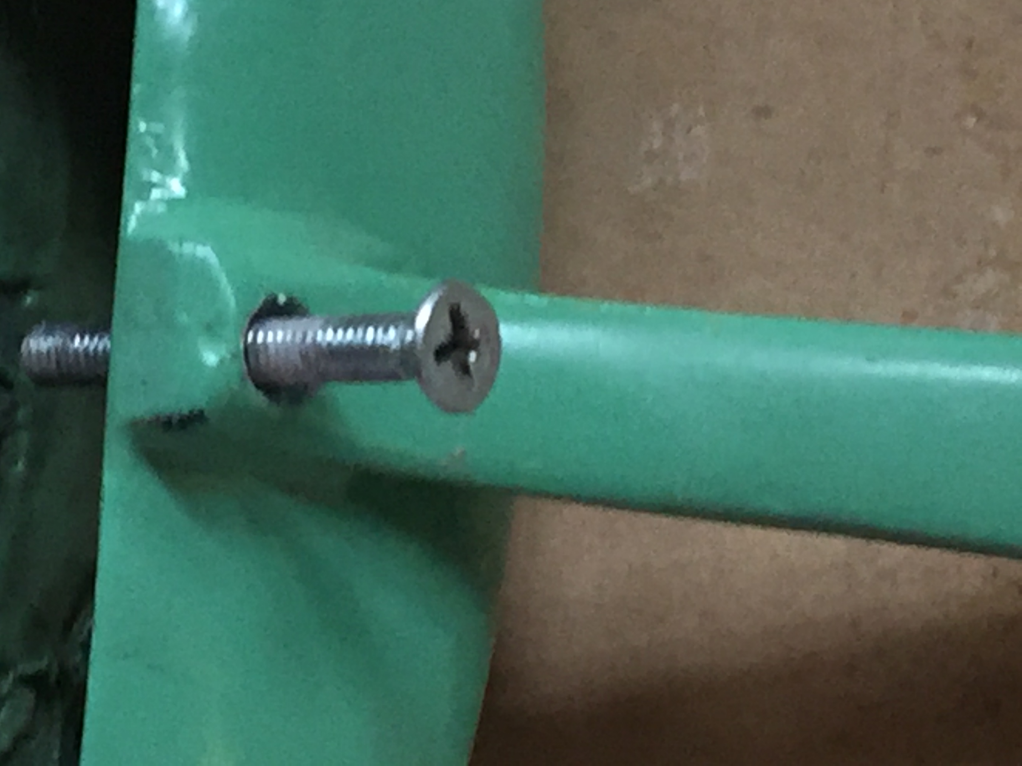
Struts and spats epoxied together. The spat has carbon cloth inside. Very strong and secure. Flat head 8-32 "axle screw" countersunk into strut

And extends to the far side of the spat, securing the outside

Self explanatory?


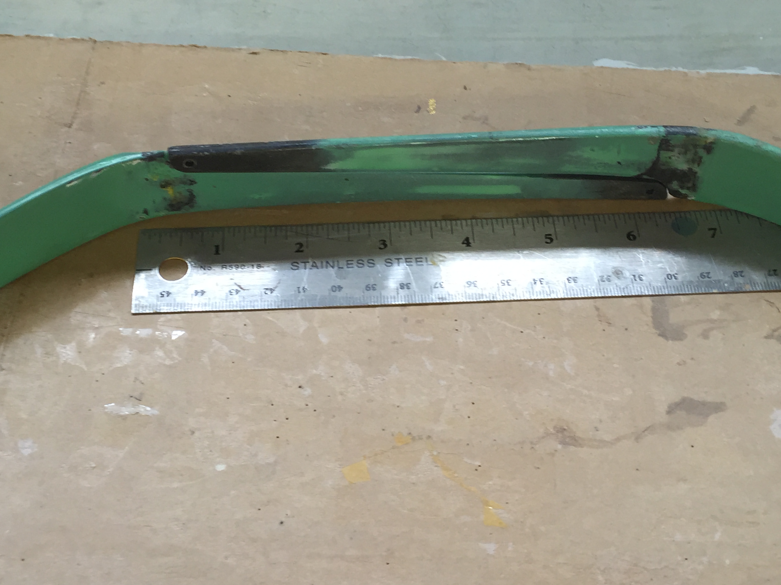
Tang length out of the mold is 7.5". It is tailored to fit any fuse width from about 8.5" to as narrow as about 4". Tangs are thinner than the rest of the strut for flex and shock absorption.
Tangs designed to fit into one another. They are fitted into sockets (not shown), which are fitted into the fuse sides. There is no orientation with this style, but could be made differently if orientation or rearward slant is wanted.
The complete gear set (strut and spat) typically weighs around 105 grams. Wheels and axles weigh whatever they weigh.
Well used spat mold....I need to build another. Shows the axle bolt areas
Outside view of mold showing the alignment tubes
Struts and spats epoxied together. The spat has carbon cloth inside. Very strong and secure. Flat head 8-32 "axle screw" countersunk into strut
And extends to the far side of the spat, securing the outside
Self explanatory?
Tang length out of the mold is 7.5". It is tailored to fit any fuse width from about 8.5" to as narrow as about 4". Tangs are thinner than the rest of the strut for flex and shock absorption.
Tangs designed to fit into one another. They are fitted into sockets (not shown), which are fitted into the fuse sides. There is no orientation with this style, but could be made differently if orientation or rearward slant is wanted.
The complete gear set (strut and spat) typically weighs around 105 grams. Wheels and axles weigh whatever they weigh.
Last edited by MTK; 07-29-2016 at 11:37 AM.