


BJ Craft Etude
 02-14-2017, 08:04 PM
#101

Remove the motor mount.
Bring the motor in from behind and install the spinner backplate, cutoff prop and spinner.
Put some medium CA glue on the metal tabs of the motor mount.
Bring up the wood motor mount from behind and while holding the spinner aligned to the front of the fuselage....press the wood motor mount in place.
After the glue kicks, remove the spinner, prop and backplate and slide the wood Motor mount and motor out the back.
Mark the motor mount holes in the wood motor mount.
Pop off the motor from the wood motor mount.
Drill holes.
Put it all back together again with Hysol.
Most guys have been using this method for many years and it works very well.
 02-14-2017, 08:15 PM
#102
Member

Join Date: Mar 2016
Location: Mesa Arizona
Posts: 33
Likes: 0
Received 0 Likes
on
0 Posts
I bolted my motor to the firewall before gluing the firewall to the fuselage. To get proper spacing and proper position, I tacked (with thin CA) four 1/2" x 3" x 2mm cf strips to the back of the spinner back plate. I then position the firewall in the fuse, put the spinner back plate on, a cutoff prop (for spacing), then the prop nut, then spinner dome. I then scuff the fuse walls with 220 grit sandpaper and clean the area with denatured alcohol. I then use painter's tape or small bungee cords to secure the spinner back plate against the front of the fuse. I then tack 4 spots of 5 min epoxy on the fuse-firewall. After that sets up, double check for perfect alignment and spacing. If all is well, I gun a generous fillet of Hysol on both sides of the firewall. Wait 24 hours and that chore is behind you.
02-15-2017, 02:29 AM
#103

What Dave says but before you install the spinner backplate, tack three 1/32" spacers 120 deg apart to the back of the backplate, so that when you hold it against the front of the fuselage there will be a small gap. If you don't do this when you finally install the motor, the backplate will touch the front of the fuselage.
Malcolm
Malcolm
 02-15-2017, 04:42 AM
#104
What Dave says but before you install the spinner backplate, tack three 1/32" spacers 120 deg apart to the back of the backplate, so that when you hold it against the front of the fuselage there will be a small gap. If you don't do this when you finally install the motor, the backplate will touch the front of the fuselage.
Malcolm
Malcolm
02-15-2017, 06:09 AM
#105
My Feedback: (8)
My original thought was to bolt the motor from the rear of the firewall directly to the motor without using the 4 point motor mount, but that does not appear to be the consensus.
Dave, i like your idea, makes the most sense. I might end up trimming the nose more than I originally anticipated to allow access to the four motor bolts. Rear mounting seemed easier on paper but I can't find a way around it.
Thanks for the help fella's
Dave, i like your idea, makes the most sense. I might end up trimming the nose more than I originally anticipated to allow access to the four motor bolts. Rear mounting seemed easier on paper but I can't find a way around it.
Thanks for the help fella's
02-15-2017, 06:22 AM
#106
My original thought was to bolt the motor from the rear of the firewall directly to the motor without using the 4 point motor mount, but that does not appear to be the consensus.
Dave, i like your idea, makes the most sense. I might end up trimming the nose more than I originally anticipated to allow access to the four motor bolts. Rear mounting seemed easier on paper but I can't find a way around it.
Thanks for the help fella's
Dave, i like your idea, makes the most sense. I might end up trimming the nose more than I originally anticipated to allow access to the four motor bolts. Rear mounting seemed easier on paper but I can't find a way around it.
Thanks for the help fella's
02-27-2017, 08:12 PM
#107
My Feedback: (8)
Here's my update.
I liken this to making a cake, you need a lot of different ingredients for it to come our right. I took a advice from the helpers here and went forward.
The firewall is installed and I can't make it any better, second time around helps too. After setting the firewall and tacking it in with some ca, using a 2 mm spacer behind the spinner backplate I realized this was TOO much of a gap. Tore it out and used a 1.1 mm spacer, much better. 32Ford set me straight here!
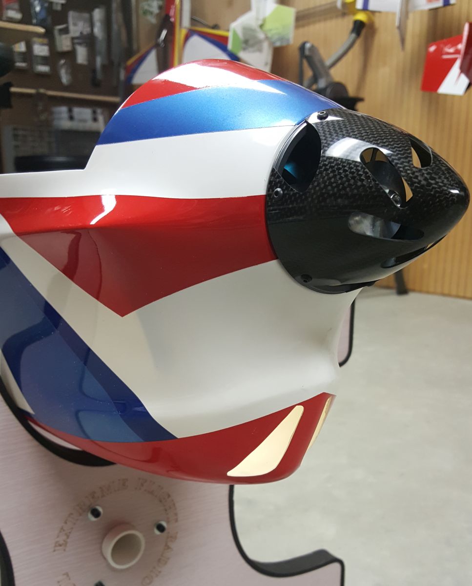
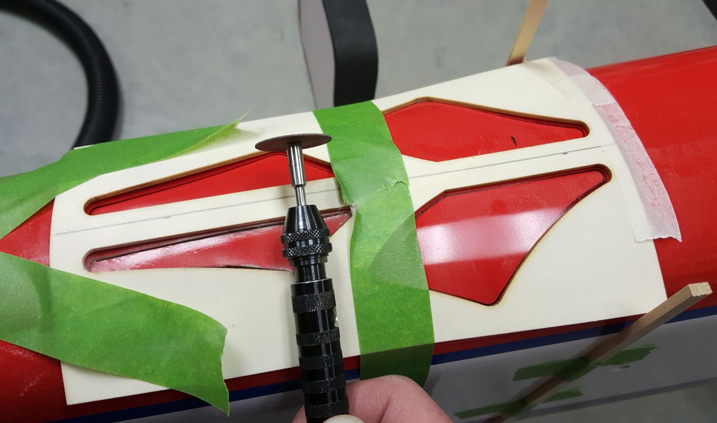
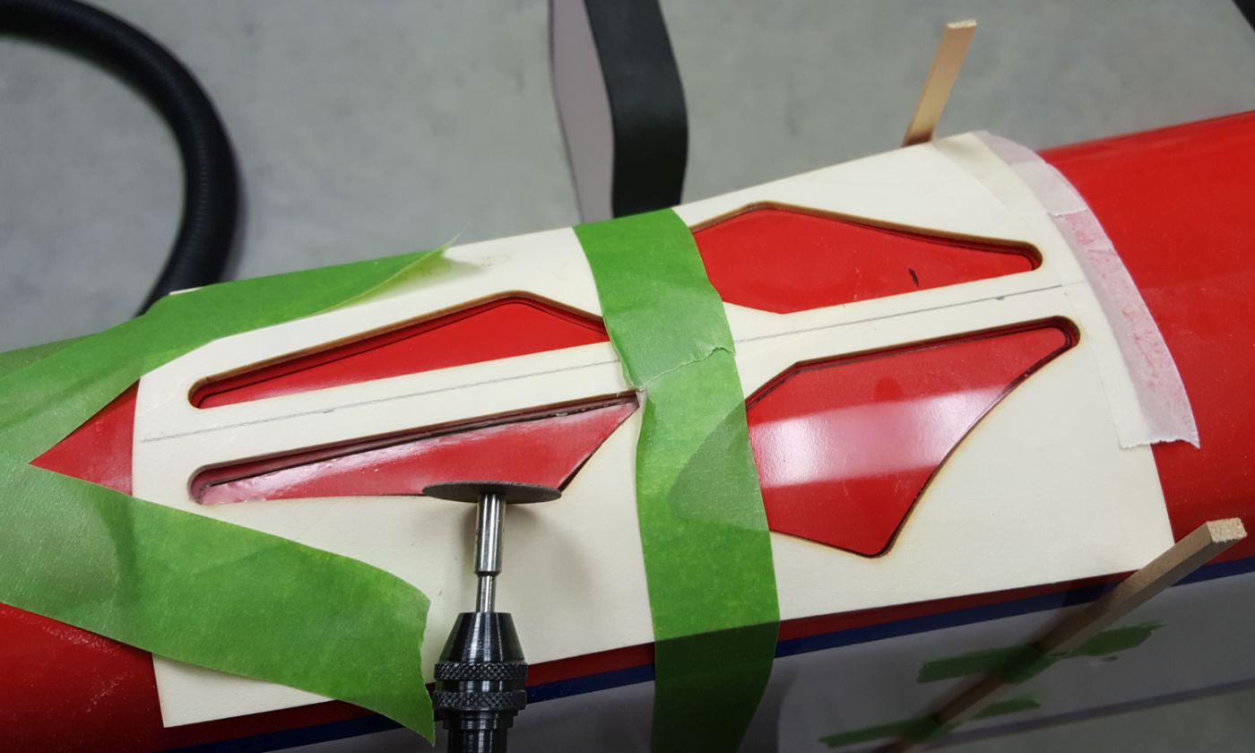
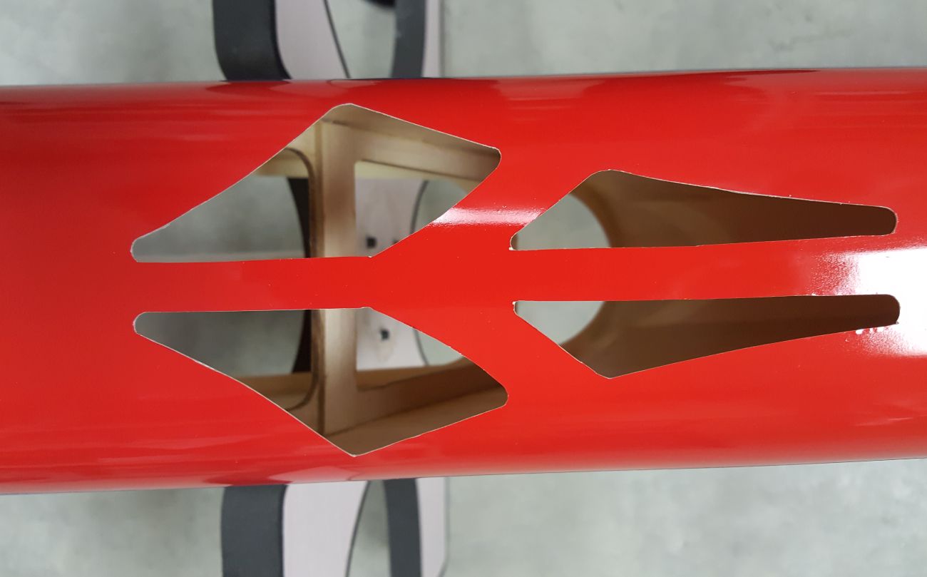
On to the cooling vents.
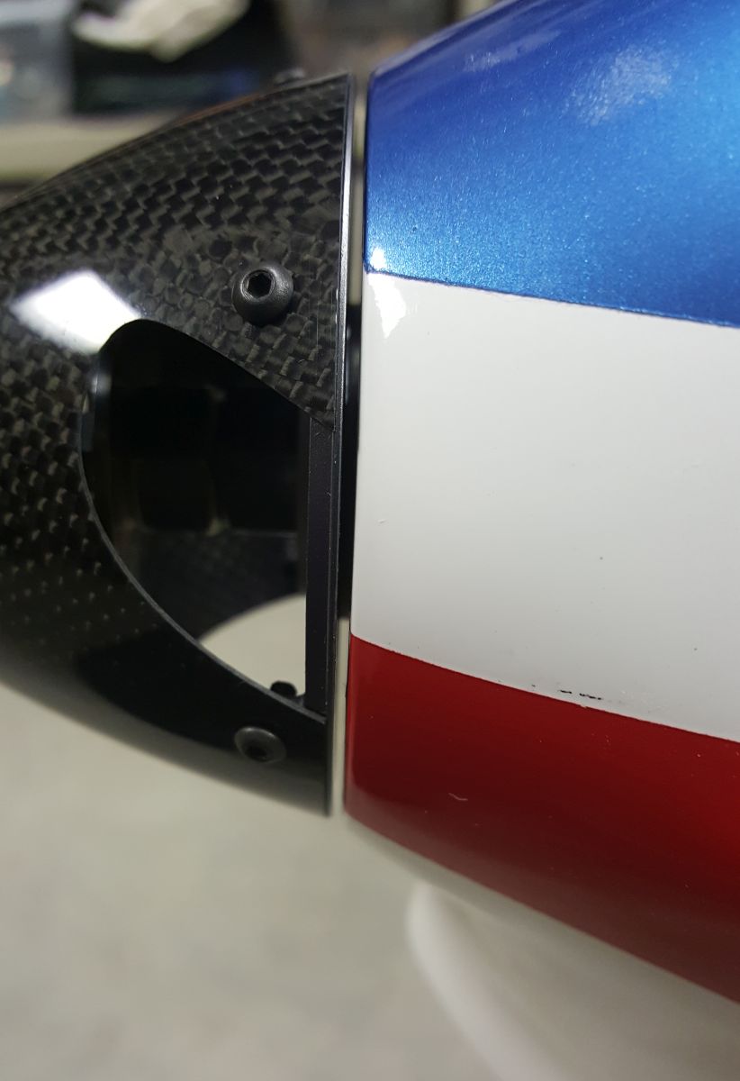
Not much to report other than trying to find the center-line of the nose ring. I layed out the tape lines on fuse where I would trace the template with a marker pen. Used a Dremel with a cut-off wheel to do the rough cut, filed and hand sanded the rest.
No matter how much time I spent on the layout It still didn't come out as symmetrical as I would have liked. It's close but needs some TLC.
I liken this to making a cake, you need a lot of different ingredients for it to come our right. I took a advice from the helpers here and went forward.
The firewall is installed and I can't make it any better, second time around helps too. After setting the firewall and tacking it in with some ca, using a 2 mm spacer behind the spinner backplate I realized this was TOO much of a gap. Tore it out and used a 1.1 mm spacer, much better. 32Ford set me straight here!
On to the cooling vents.
Not much to report other than trying to find the center-line of the nose ring. I layed out the tape lines on fuse where I would trace the template with a marker pen. Used a Dremel with a cut-off wheel to do the rough cut, filed and hand sanded the rest.
No matter how much time I spent on the layout It still didn't come out as symmetrical as I would have liked. It's close but needs some TLC.
02-28-2017, 05:28 AM
#108
Member
Join Date: Mar 2016
Location: Mesa Arizona
Posts: 33
Likes: 0
Received 0 Likes
on
0 Posts
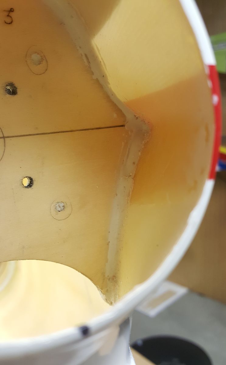
Looks very good. I must have used 1.0mm cf strips for my spinner backplate spacing as my clearance is much less than your 2mm picture. I would sure go back and make sure that the Hysol filet is around the entirety of the firewall-fuse contact area. Your picture doesn't appear to have a filet across the top of the structure. The vent holes on the nose look fine to do the job. Be careful cutting the ones on the bottom of the fuse aft of the canopy compartment. That area of the fuse is really thin, egg shell thin at most. I reinforced mine structurally after cutting the vent hole pattern.
02-28-2017, 05:44 AM
#109
My Feedback: (8)
Yes, I knew you would pick out the LACK of adhesive used. This was the first application to secure the firewall. I did apply an entire bead on both side of the firewall, pictures forthcoming in the next round. The difficult part was trying to apply epoxy behind the firewall where it meet the top deck of the fuselage, pretty tight fit.
The spacing on the spinner was after my second attempt, I'm not showing the first round, it was ugly.
I used the same motor on my Caelus and noticed after a number of flight the prop shaft moves fore and aft, hence my 1 mm gap.
The spacing on the spinner was after my second attempt, I'm not showing the first round, it was ugly.
I used the same motor on my Caelus and noticed after a number of flight the prop shaft moves fore and aft, hence my 1 mm gap.
Last edited by mgosson; 02-28-2017 at 05:47 AM.
02-28-2017, 06:18 AM
#110

It may be a good idea to add a piece of carbon fiber plate (0.75mm) of the size of the motor on the back of the firewall (like the front one). This can help prevent the washers being pushed into the firewall and secure the motor better.
On my front-mounted Pletty, I added one piece from the front for the same purpose.
On my front-mounted Pletty, I added one piece from the front for the same purpose.
02-28-2017, 10:07 AM
#112

My Feedback: (2)

Join Date: Jan 2002
Location: Ossining,
NY
Posts: 630
Likes: 0
Received 0 Likes
on
0 Posts
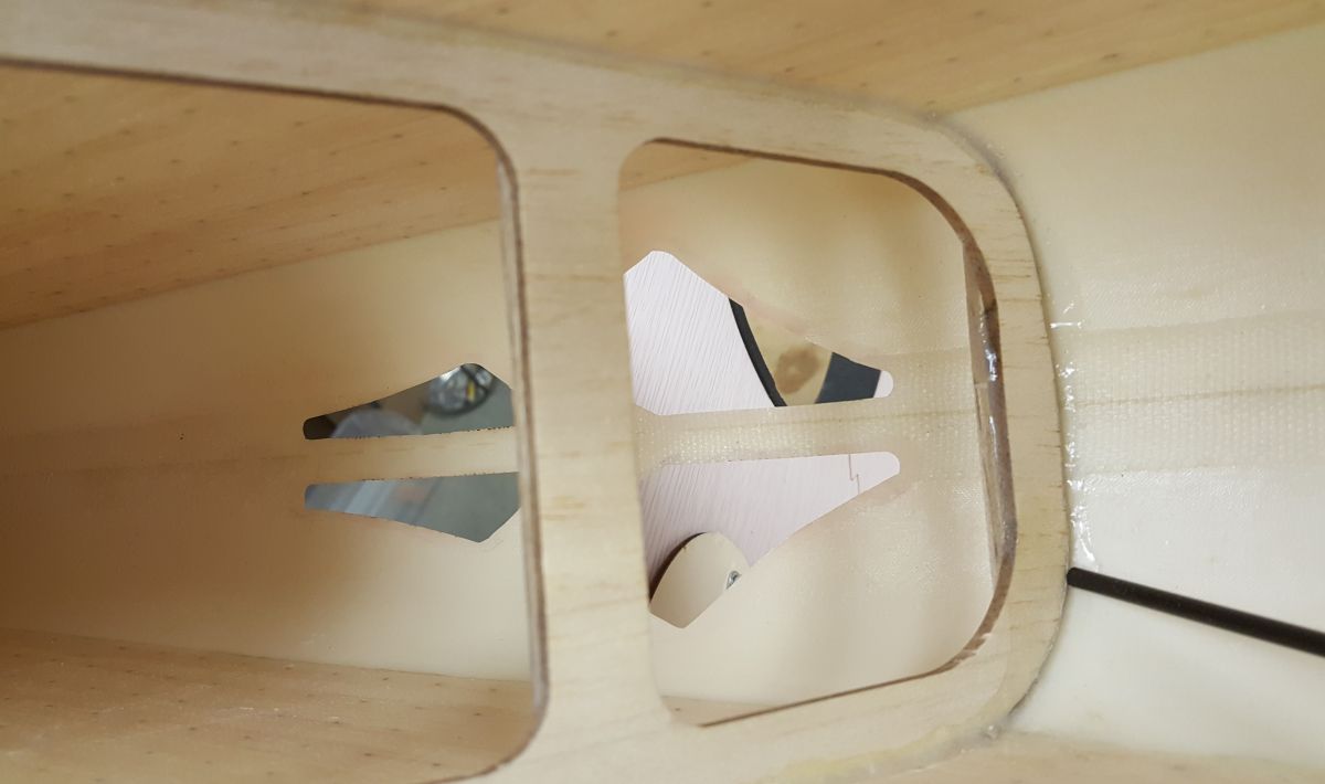
Nice work Mike! A mirror and a flashlight in the fuse can work well to let you see into the dark corners. Don't let the paint fool you either because it is never as symmetrical as you think.
03-01-2017, 02:44 PM
#119
03-01-2017, 07:43 PM
#120
My Feedback: (8)
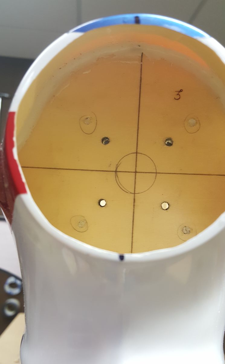
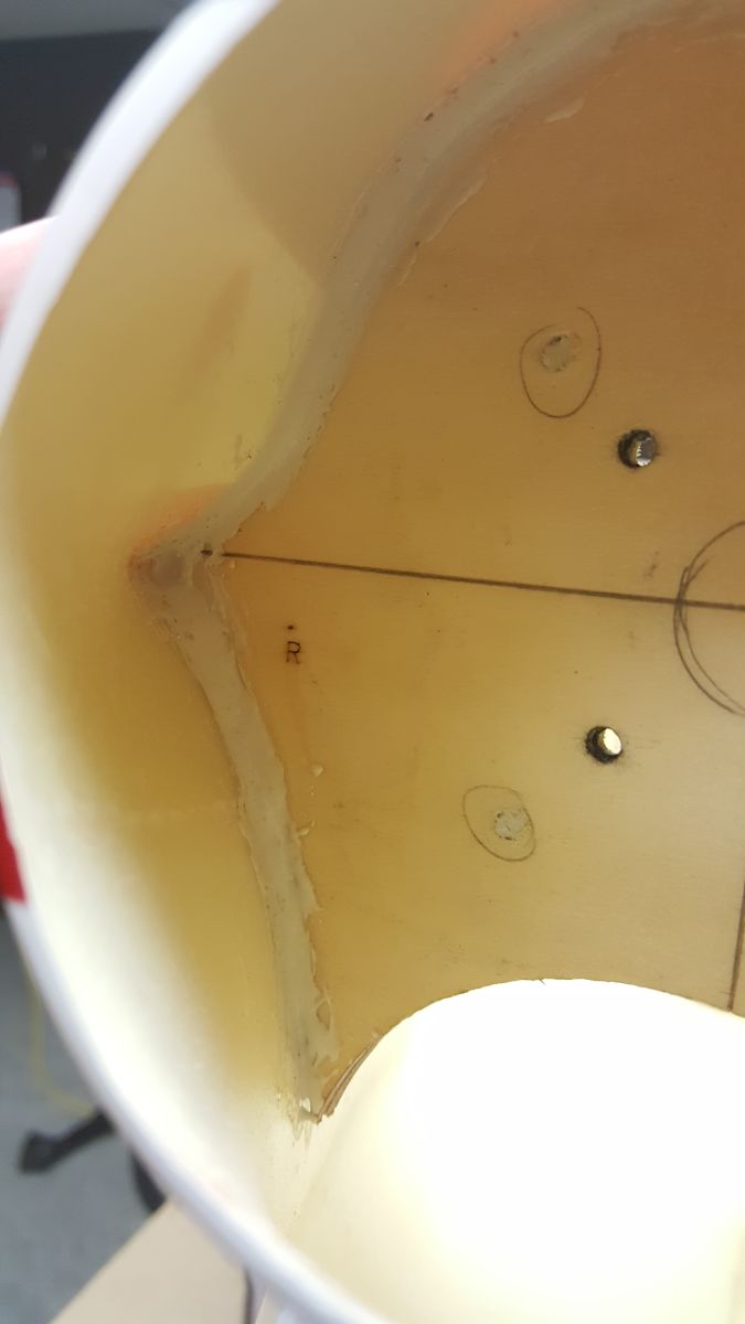
The firewall is now completed.
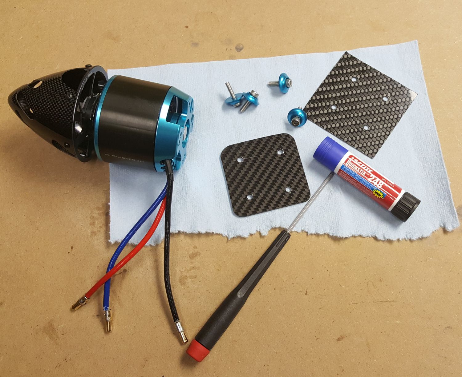
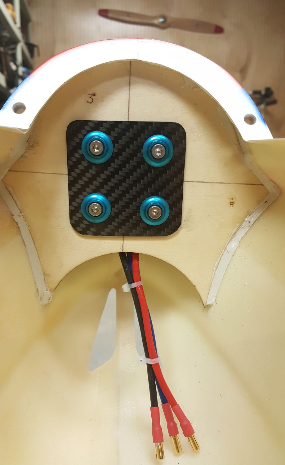
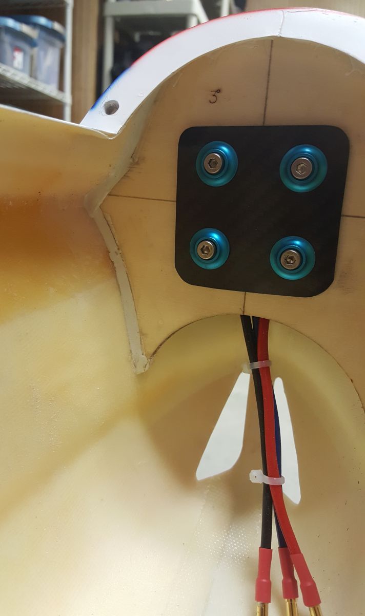
Soldered 4 mm Castle bullet connectors to the Himax 6330-210 motor leads, added heat shrink tubing. Connected to a 70 mm Falcon three blade spinner.
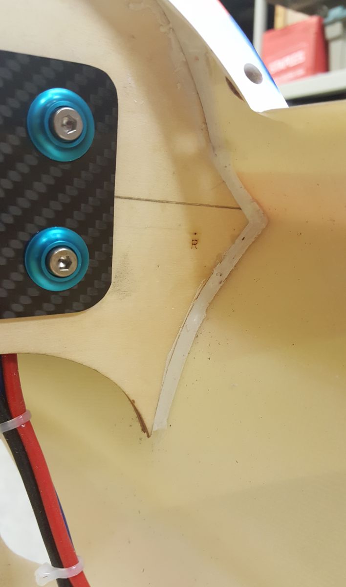
I used Hysol 1C (that's what I had while waiting for the HP 60 to arrive). The adhesive sets up in 25 minutes, dries white and easy to work with. Applied an adequate amount on both sides of the firewall. To keep the lines of epoxy straight I placed masking tape to the fuse and the firewall to replace an ugly mess. Spread the epoxy, worked into the gaps and removed the tape.
I placed a 1 mm carbon fiber sheet sandwiched between the motor and firewall with a 2 mm plate on the rear of the firewall. This helps spread the load when you wrench down on the motor mounting bolts, IMO, and prevents the oversize washers from crushing the wood. Applied loctite thread locking paste (blue) to the motor bolts and called it a day.
This is as good as I get.
Next step, cut the cooling vents on the underside of the fuselage.

Soldered 4 mm Castle bullet connectors to the Himax 6330-210 motor leads, added heat shrink tubing. Connected to a 70 mm Falcon three blade spinner.
I used Hysol 1C (that's what I had while waiting for the HP 60 to arrive). The adhesive sets up in 25 minutes, dries white and easy to work with. Applied an adequate amount on both sides of the firewall. To keep the lines of epoxy straight I placed masking tape to the fuse and the firewall to replace an ugly mess. Spread the epoxy, worked into the gaps and removed the tape.
I placed a 1 mm carbon fiber sheet sandwiched between the motor and firewall with a 2 mm plate on the rear of the firewall. This helps spread the load when you wrench down on the motor mounting bolts, IMO, and prevents the oversize washers from crushing the wood. Applied loctite thread locking paste (blue) to the motor bolts and called it a day.
This is as good as I get.
Next step, cut the cooling vents on the underside of the fuselage.
Last edited by mgosson; 03-02-2017 at 06:46 AM.
03-02-2017, 08:10 PM
#121
My Feedback: (8)
The saga continues.
This had to be one of the easiest jobs I've completed on the plane so far. It really does help when you spend about an hour digging through various sites and photos. Much time could be saved if you supplied some sort of building manual. I hope someone here can benefit from my photo postings.
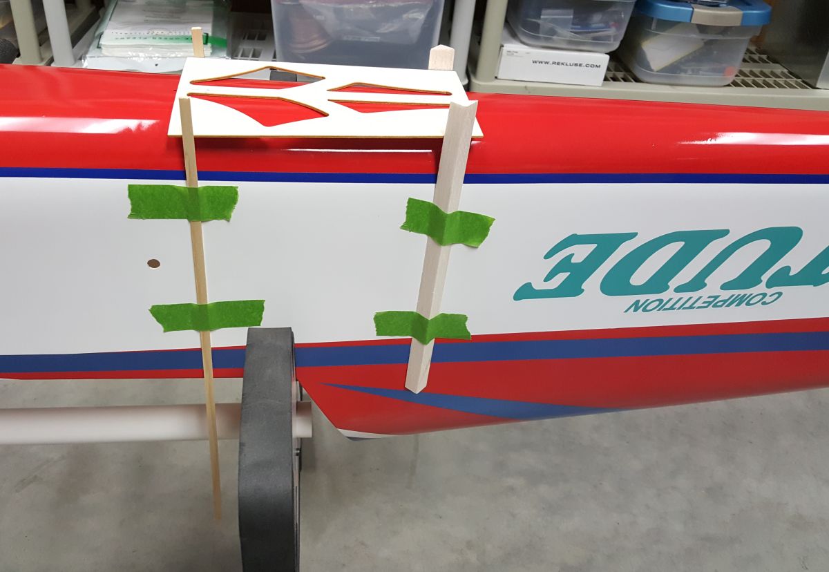
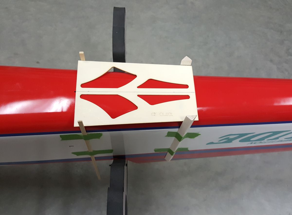
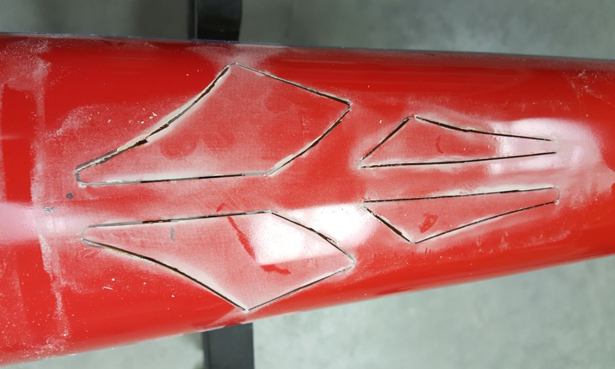
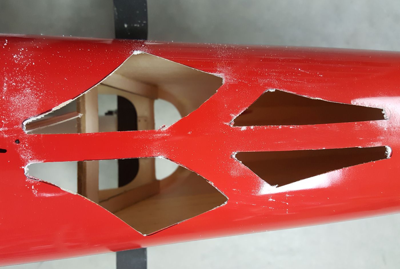
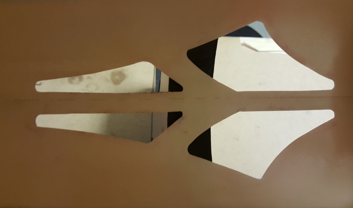
The trick was knowing exactly where to place the supplied wood template on the fuselage. After looking at a few photos it became clear it needed to be placed behind the former aft of the trailing edge of the wing.
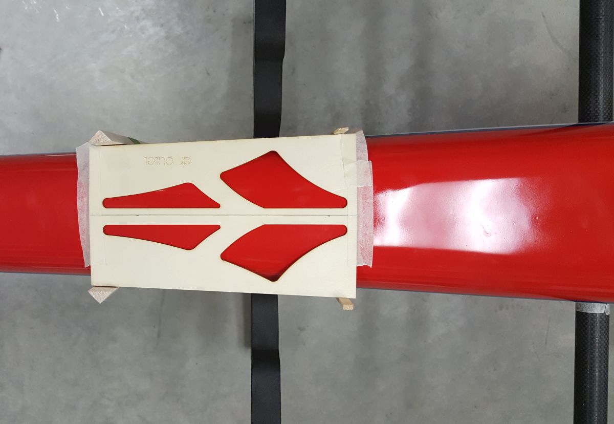
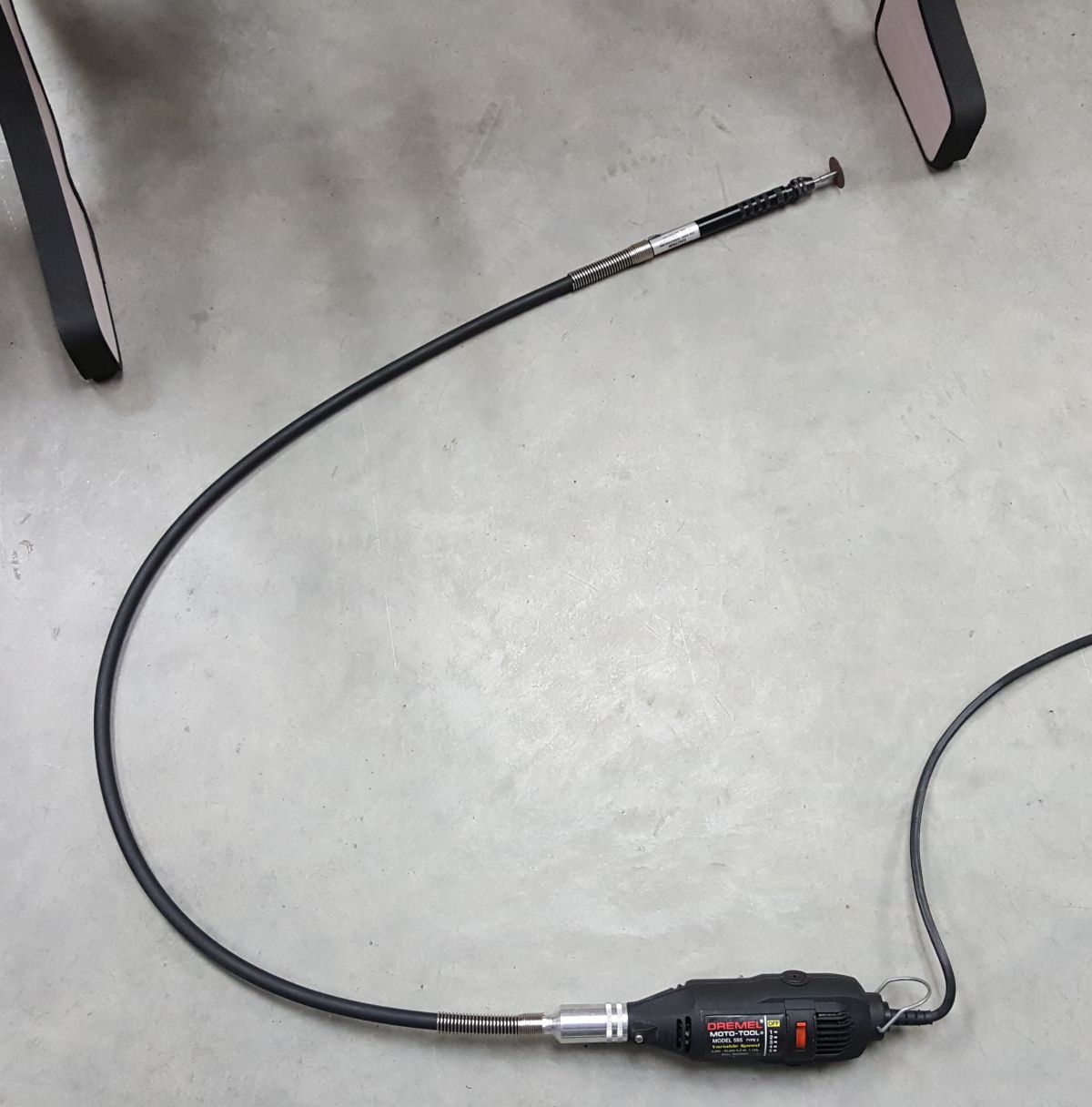
I taped 4 balsa pieces to the fuselage and placed the light ply template between the balsa stock. It lined up pretty close. Took a few more measurements and taped the template to the fuselage. Proceeded to mark the fuse with a marking pen to make the lines more pronounced. Took my Dremel with the snake extension and a cut-off wheel, the snake cable is one handy gizmo to have. Put the Dremel to work and cut inside the template where I could and finished cutting the fine edges with a micro cutter bit. Placed the fine grind stone on the snake and rounded the corners. Removed the template and finish sanded all the edges to clean it up.
This had to be one of the easiest jobs I've completed on the plane so far. It really does help when you spend about an hour digging through various sites and photos. Much time could be saved if you supplied some sort of building manual. I hope someone here can benefit from my photo postings.
The trick was knowing exactly where to place the supplied wood template on the fuselage. After looking at a few photos it became clear it needed to be placed behind the former aft of the trailing edge of the wing.
I taped 4 balsa pieces to the fuselage and placed the light ply template between the balsa stock. It lined up pretty close. Took a few more measurements and taped the template to the fuselage. Proceeded to mark the fuse with a marking pen to make the lines more pronounced. Took my Dremel with the snake extension and a cut-off wheel, the snake cable is one handy gizmo to have. Put the Dremel to work and cut inside the template where I could and finished cutting the fine edges with a micro cutter bit. Placed the fine grind stone on the snake and rounded the corners. Removed the template and finish sanded all the edges to clean it up.
03-02-2017, 08:27 PM
#122
Looks good....that's the same way I did it.
You can put some thin CA on your finger and run it around on the inside of the cuts to keep the paint from chipping away as it ages.
You can put some thin CA on your finger and run it around on the inside of the cuts to keep the paint from chipping away as it ages.
03-14-2017, 06:08 PM
#125
My Feedback: (8)
On to phase ????
It's time to install the wing adjusters. I ordered a set of wing adjusters from F3A, the style best suited for the BJ Craft birds and decided to mount them in the leading edge, no specific reason to mount them there, just looked easier. Installed the oem set in the rear.
In the past I've typically used the canopy line to gain a reference point and I could not have more mistaken. The zero line is taken from the stab tubes and set the wing incidence to the stab tubes.
I must have spent 2 hours measuring and couldn't figure it out. If it were not for the help of 32Ford I would still be scratching my head. I called him on the phone and within 15 minutes he set me straight, he really bailed me out.
Much of this could be avoided if BJ Craft supplied some sort of building manual, the Caelus I built last year is really a cut above when it comes to instructions.
Here's a rundown of the photo build.
Thanks 32Ford I owe you!
Last edited by mgosson; 03-15-2017 at 05:46 AM.