


Oxai Galactika unboxing, assembly, setup, maiden etc.
 04-26-2016, 05:06 PM
#1
Hi,
Here start, as I promised in another thread, my Oxai Galactika unboxing, assembly, setup, maiden and further trimming, flights etc.
The plane is already flown so it will be a recap for me about the previous stages. I will try to give as valuable info about this plane for You as I can.
For those that do not know, Galactika (with a last in name) is the latest (2015) version of current F3A World Champion (8 times winner) Christophe Paysant-Le Roux (CPLR) design. The previous version was Galactik. I will discuss some of the difference (I know of) between them later in this thread.
So I will devide this thread in these main parts:
1. Unboxing.
2. Assembly.
3. Setup.
4. Maiden.
5. Trimming process.
6. Flighttraining (mainly for P-17 Schedule)
7. Competition flying (that I will participate in)
I hope You will make comments as I make posts.
If You have a Galactik or Galactika please add comments, photos etc of Your plane here also if You want, so we can gather as much info about the planes here.
It is sad that Oxai has descided to stop production of their F3A planes at June 2016.
So maybe this thread about Oxai Galactika will be the only one on Galactika here at RCU (or elsewhere?).
Maybe someone ask, why would anyone buy an Oxai plane when it has such high price tag (yes, it has)?
For me it is once in a lifetime purchase of such expensive F3A model. I was actually wating for Sebart to release for purchase the new PrometheuS monoplane but since it has not been released yet I could not wait any longer and then I decided I wanted an Oxai Galactika for the excellent build quality, finish and known good flight characteristics (it is after all the 2015 WC model).
Since it will be made no more Galactika, at least not by Oxai, I will have to take extra care of my model and I plan to use it at least 3 seasons before I retire it (if it will survive that long).
I bought my Galactika here in Europe from F3A Lorenz in Germany (I live in Sweden myself).
The pricetag was 4195 Euro (US$ 4727) plus shipping 90 Euro ($101).
My Galactika arrived to me door Feb 17 2016. I had to be home from work that day since I had to receive the box and inspect it for any external box damage at arrival. The box that arrived was large, as expected, and the plane was very well packed inside the box. The dealer had it out of the box and inspected it before it was shipped to me. After I received the box it was time for unboxing.
1. Unboxing.
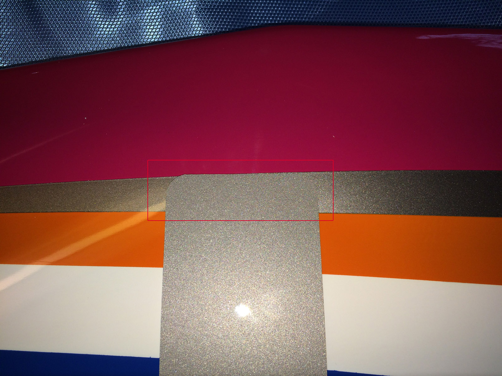
It was with great excitment I started to unbox my Galactika. Part after part was taken out of the box and inspected. All seemed to be undamaged at first. But when I took the Oxai original blue fabric transport cover off the fuselage I discovered a rather severe crack on top of fuselage, about 90 millimeter (3.54 inch) long. The crack was through outer glass fibre, the laminate and also inner glass fibre layer.
I contacted the dealer and sent photos of the damage. After some e-mail conversation we settled for a fair price reduction for the transport damage. It is a mystery to me how the damage could happen in the box since it was maybe one feet up to ceiling of the box from the damage on the fuselage, and it was no damage at all on the box the model was shipped in. I have some photos below of the unboxing and inspection of the model.
After the unboxing I layed out the parts and took some photos. see below. I took some measurments of wing, stab, T-canard and rudder also, see photos of that below.
Maybe some of You, that have never seen an Oxai model ask how good quality is it on such model as Galactika?
For me I can compare with Sebart models (my last was a MythoS Pro), they have without doubt good build quality and good quality on painting and plastic film covering (wing+stab) in my opinion. But my Oxai Galactika is considerably better build quality (what can be seen) and finish (the whole plane is painted and clear coated) is amazing. It is like a new car paint job if I would compare to semething else. It is so good finish that I think most people wold say "Wow!". Personally I have never seen any better finish on a F3A plane then this, especially when You can inspect the paint job in detail.
The surface on my Galactika is rather fragile I have discovered, so one have to be extra careful while handling the plane at transport, in/out of the house to/from car and on the work bench. The nice light blue original Oxai transport cover for the whole model is really needed.
Fuselage is composite with thin glass fibre outer layer, then a little thicker material almost like depron and last an inner thin glass fibre layer. It is also reinforcements with carbon fibre in fuselage nose and lower part of fuselage back to air vent outlet. Wing, stab and all control surfaces are built up balsa structure, covered with some thin "paper" (maybe Esaki tissue). Whole model is of course beautifully spray painted and everything is finished with clear coat.
The model has all control surfaces hinged from the factory, and they are very good aligned, also they allow rather large throws.
Rudder and elevators has straight trailing edges, so it is not curved out (like it is on Sebart MythoS Pro for example).
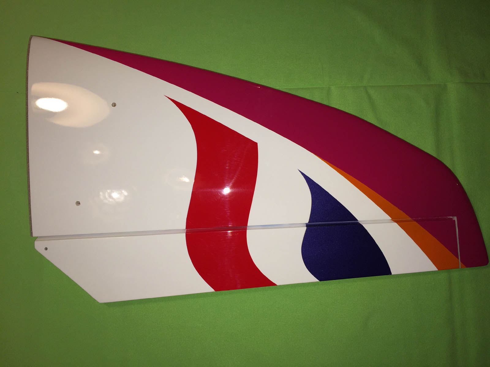
The rudder is large but the elevators are rather small. Ailerons are rather large. Se photos below with measurements.
I have not taken any measurments on the fuselage but I can do that on request.
Photos below: 1-14 unboxing and fuselage transport damage, 15-31 wing, stab, T-canard etc (post #2).
This complete part 1. Unboxing.
Up next will be part 2. Assembly. (starting that part maybe tomorrow)
regards,
Bo

The huge box with Galactika arrived Feb 17 2016 to me.

Very well packed inside the transportation box.
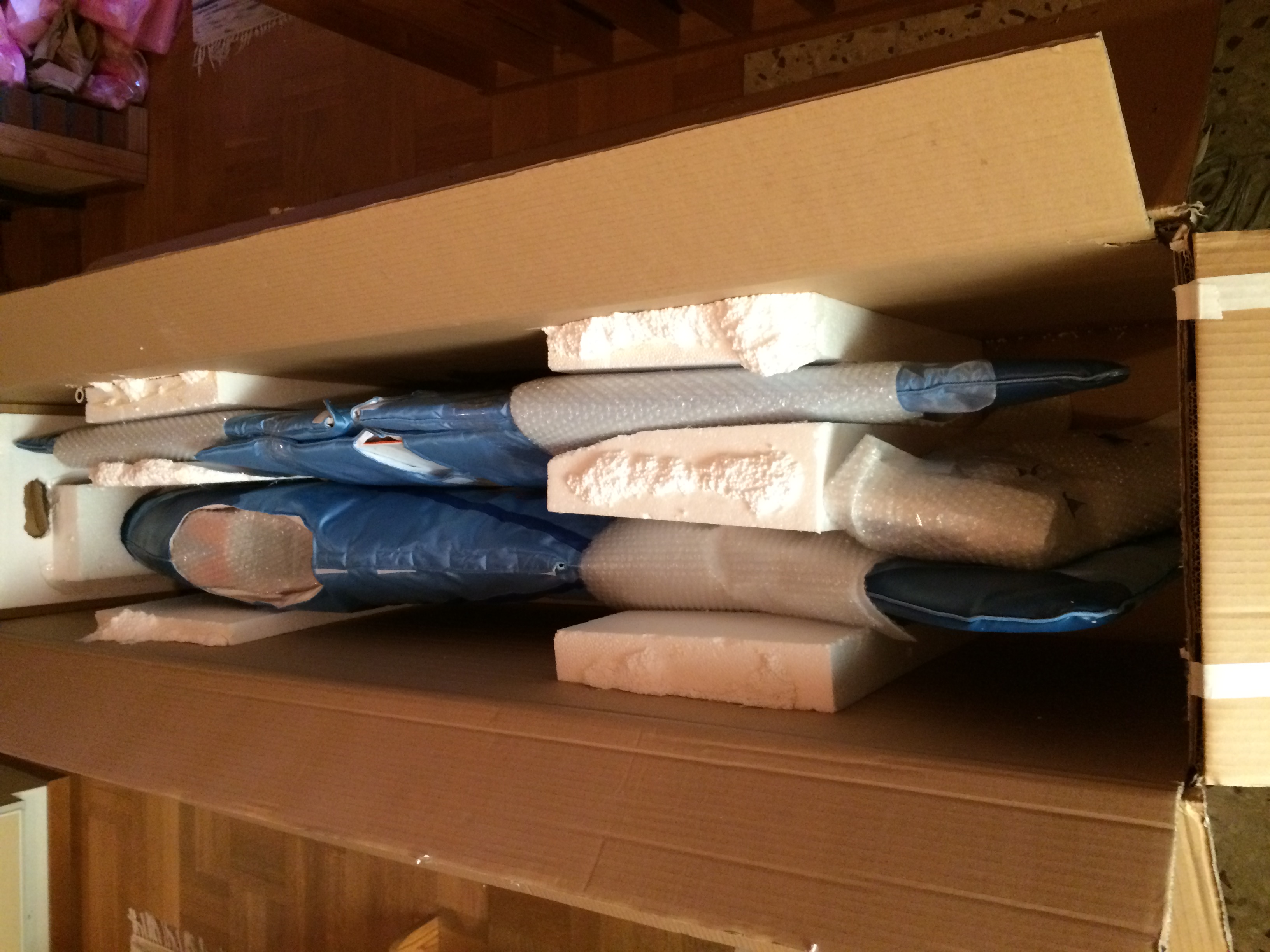
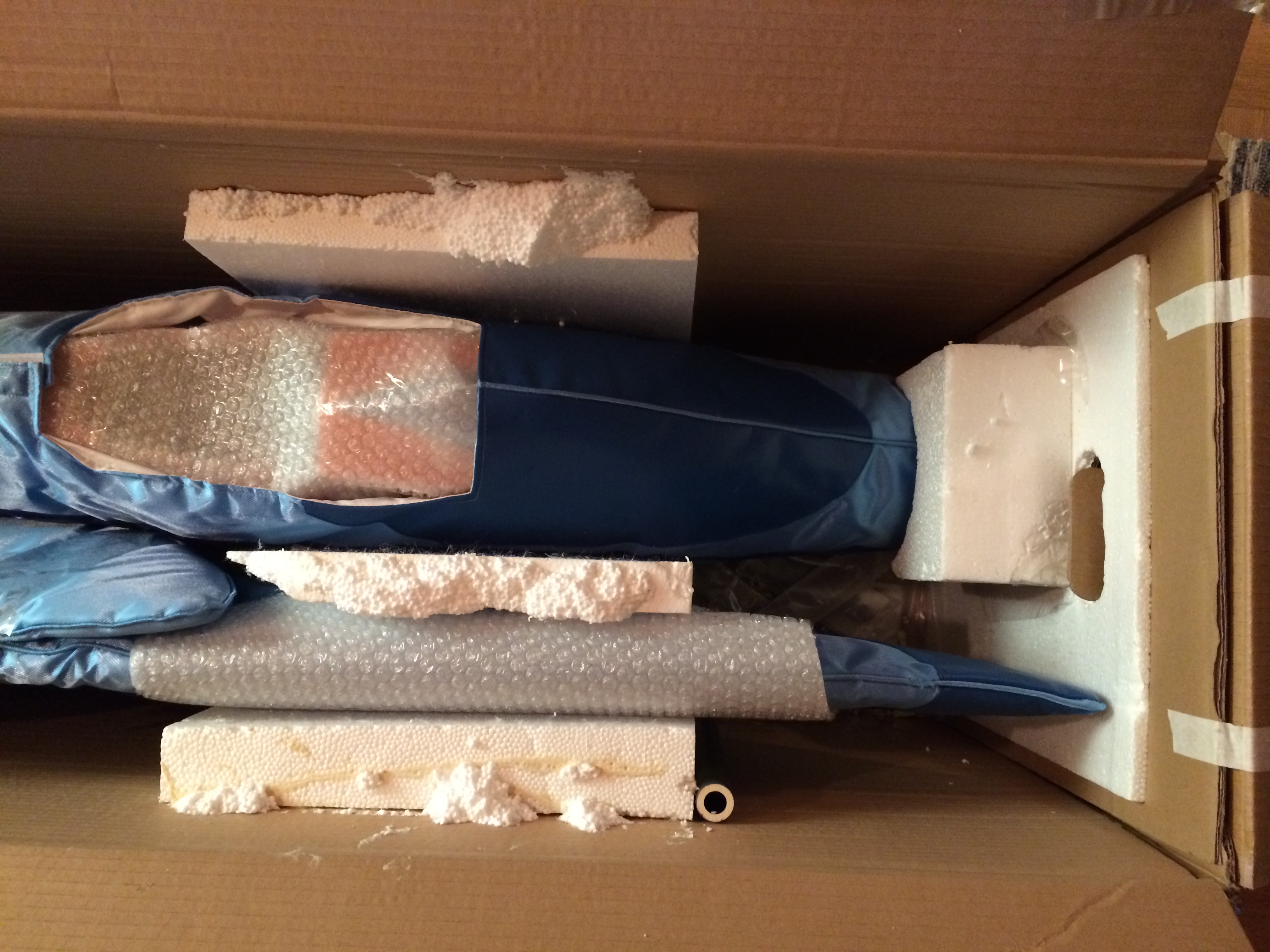

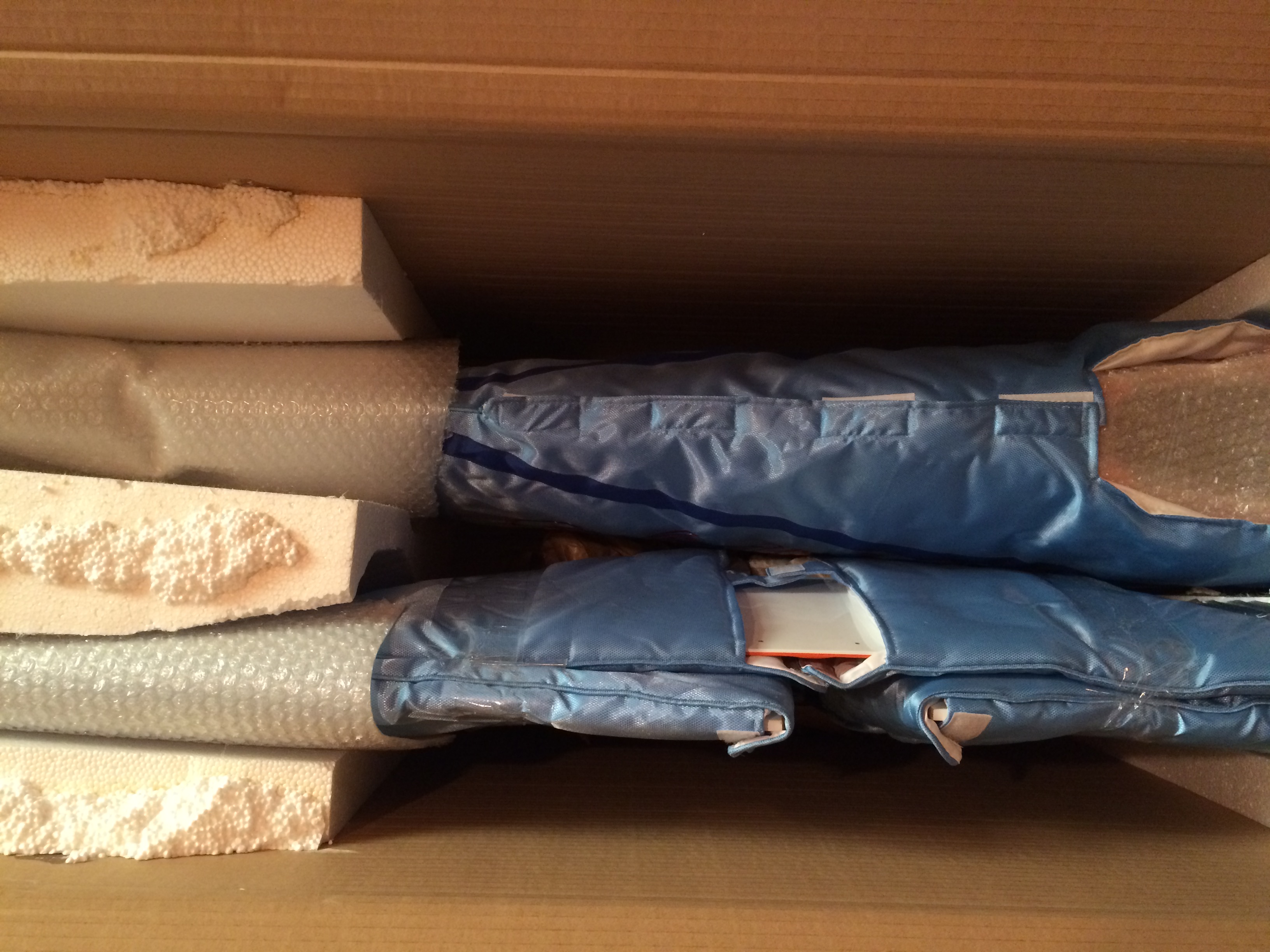

All the padding inside the box taken out.


Galactika is out of the box and inspection begin, and when fuselage is taken out of the Oxai blue fuselage cover a crack is found.


The crack on top of fuselage.
Here start, as I promised in another thread, my Oxai Galactika unboxing, assembly, setup, maiden and further trimming, flights etc.
The plane is already flown so it will be a recap for me about the previous stages. I will try to give as valuable info about this plane for You as I can.
For those that do not know, Galactika (with a last in name) is the latest (2015) version of current F3A World Champion (8 times winner) Christophe Paysant-Le Roux (CPLR) design. The previous version was Galactik. I will discuss some of the difference (I know of) between them later in this thread.
So I will devide this thread in these main parts:
1. Unboxing.
2. Assembly.
3. Setup.
4. Maiden.
5. Trimming process.
6. Flighttraining (mainly for P-17 Schedule)
7. Competition flying (that I will participate in)
I hope You will make comments as I make posts.
If You have a Galactik or Galactika please add comments, photos etc of Your plane here also if You want, so we can gather as much info about the planes here.
It is sad that Oxai has descided to stop production of their F3A planes at June 2016.
So maybe this thread about Oxai Galactika will be the only one on Galactika here at RCU (or elsewhere?).
Maybe someone ask, why would anyone buy an Oxai plane when it has such high price tag (yes, it has)?
For me it is once in a lifetime purchase of such expensive F3A model. I was actually wating for Sebart to release for purchase the new PrometheuS monoplane but since it has not been released yet I could not wait any longer and then I decided I wanted an Oxai Galactika for the excellent build quality, finish and known good flight characteristics (it is after all the 2015 WC model).
Since it will be made no more Galactika, at least not by Oxai, I will have to take extra care of my model and I plan to use it at least 3 seasons before I retire it (if it will survive that long).
I bought my Galactika here in Europe from F3A Lorenz in Germany (I live in Sweden myself).
The pricetag was 4195 Euro (US$ 4727) plus shipping 90 Euro ($101).
My Galactika arrived to me door Feb 17 2016. I had to be home from work that day since I had to receive the box and inspect it for any external box damage at arrival. The box that arrived was large, as expected, and the plane was very well packed inside the box. The dealer had it out of the box and inspected it before it was shipped to me. After I received the box it was time for unboxing.
1. Unboxing.
It was with great excitment I started to unbox my Galactika. Part after part was taken out of the box and inspected. All seemed to be undamaged at first. But when I took the Oxai original blue fabric transport cover off the fuselage I discovered a rather severe crack on top of fuselage, about 90 millimeter (3.54 inch) long. The crack was through outer glass fibre, the laminate and also inner glass fibre layer.
I contacted the dealer and sent photos of the damage. After some e-mail conversation we settled for a fair price reduction for the transport damage. It is a mystery to me how the damage could happen in the box since it was maybe one feet up to ceiling of the box from the damage on the fuselage, and it was no damage at all on the box the model was shipped in. I have some photos below of the unboxing and inspection of the model.
After the unboxing I layed out the parts and took some photos. see below. I took some measurments of wing, stab, T-canard and rudder also, see photos of that below.
Maybe some of You, that have never seen an Oxai model ask how good quality is it on such model as Galactika?
For me I can compare with Sebart models (my last was a MythoS Pro), they have without doubt good build quality and good quality on painting and plastic film covering (wing+stab) in my opinion. But my Oxai Galactika is considerably better build quality (what can be seen) and finish (the whole plane is painted and clear coated) is amazing. It is like a new car paint job if I would compare to semething else. It is so good finish that I think most people wold say "Wow!". Personally I have never seen any better finish on a F3A plane then this, especially when You can inspect the paint job in detail.
The surface on my Galactika is rather fragile I have discovered, so one have to be extra careful while handling the plane at transport, in/out of the house to/from car and on the work bench. The nice light blue original Oxai transport cover for the whole model is really needed.
Fuselage is composite with thin glass fibre outer layer, then a little thicker material almost like depron and last an inner thin glass fibre layer. It is also reinforcements with carbon fibre in fuselage nose and lower part of fuselage back to air vent outlet. Wing, stab and all control surfaces are built up balsa structure, covered with some thin "paper" (maybe Esaki tissue). Whole model is of course beautifully spray painted and everything is finished with clear coat.
The model has all control surfaces hinged from the factory, and they are very good aligned, also they allow rather large throws.
Rudder and elevators has straight trailing edges, so it is not curved out (like it is on Sebart MythoS Pro for example).
The rudder is large but the elevators are rather small. Ailerons are rather large. Se photos below with measurements.
I have not taken any measurments on the fuselage but I can do that on request.
Photos below: 1-14 unboxing and fuselage transport damage, 15-31 wing, stab, T-canard etc (post #2).
This complete part 1. Unboxing.
Up next will be part 2. Assembly. (starting that part maybe tomorrow)
regards,
Bo
The huge box with Galactika arrived Feb 17 2016 to me.
Very well packed inside the transportation box.
All the padding inside the box taken out.
Galactika is out of the box and inspection begin, and when fuselage is taken out of the Oxai blue fuselage cover a crack is found.
The crack on top of fuselage.
Last edited by bem; 05-09-2016 at 03:07 PM.
 04-26-2016, 05:42 PM
#2
Cont.
See photos.
Note measurments made on wing, stab, T-canard and rudder.
/Bo
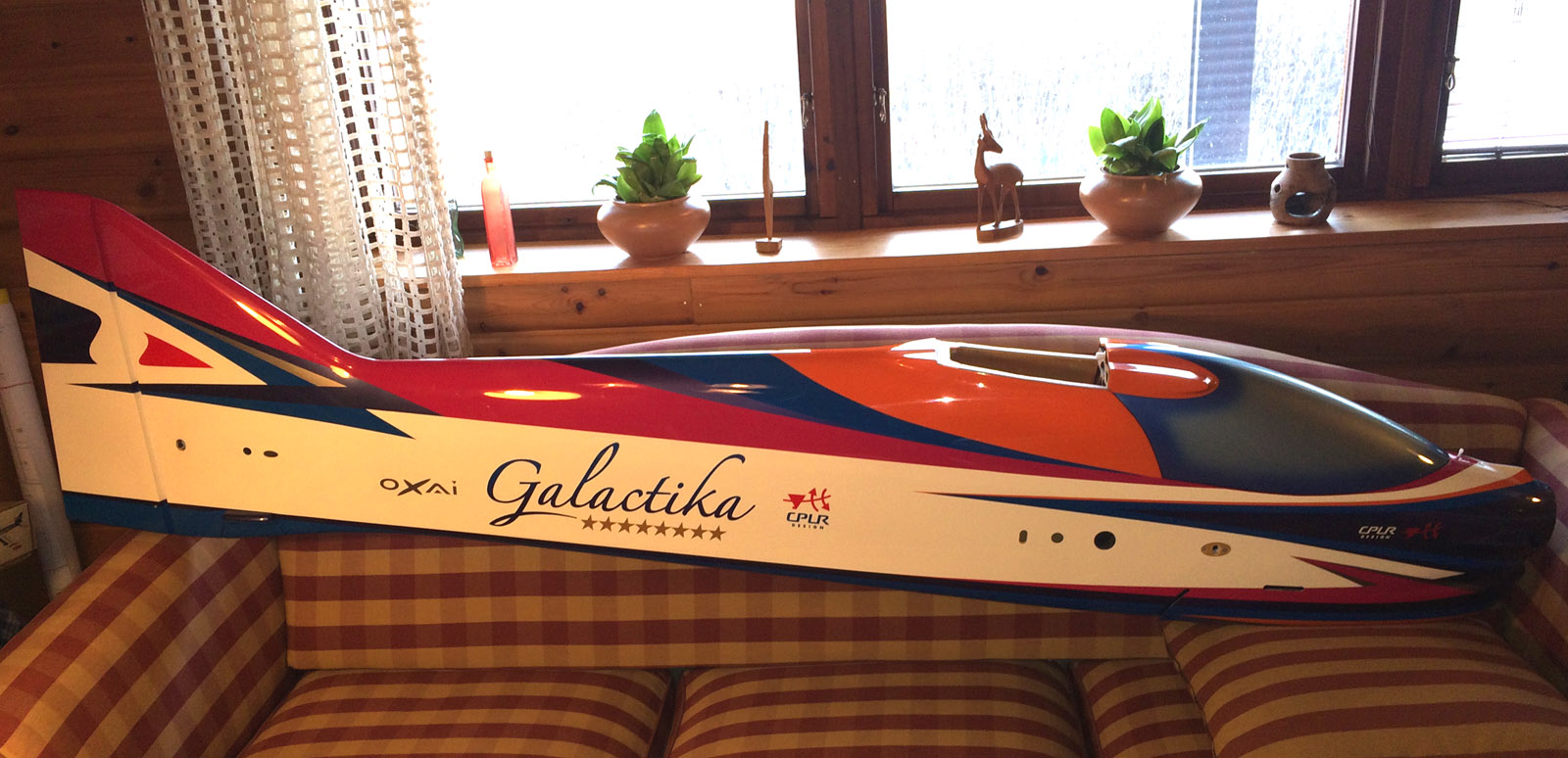
Fuselage in all it's shiny glory.


Wing measured, understide wing and wing root profile.


Stab measured, stab underside and stab root profile.
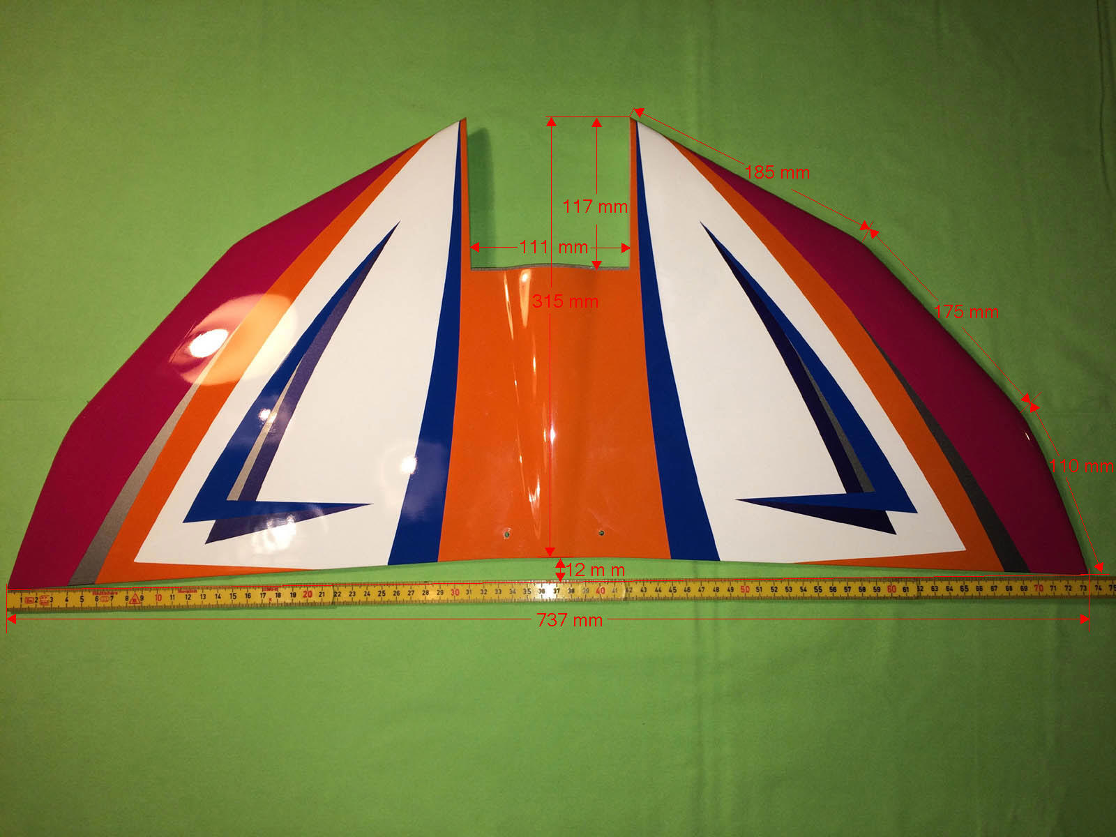

T-canard measured and T-canard mounting points.

Canopy all carbon.

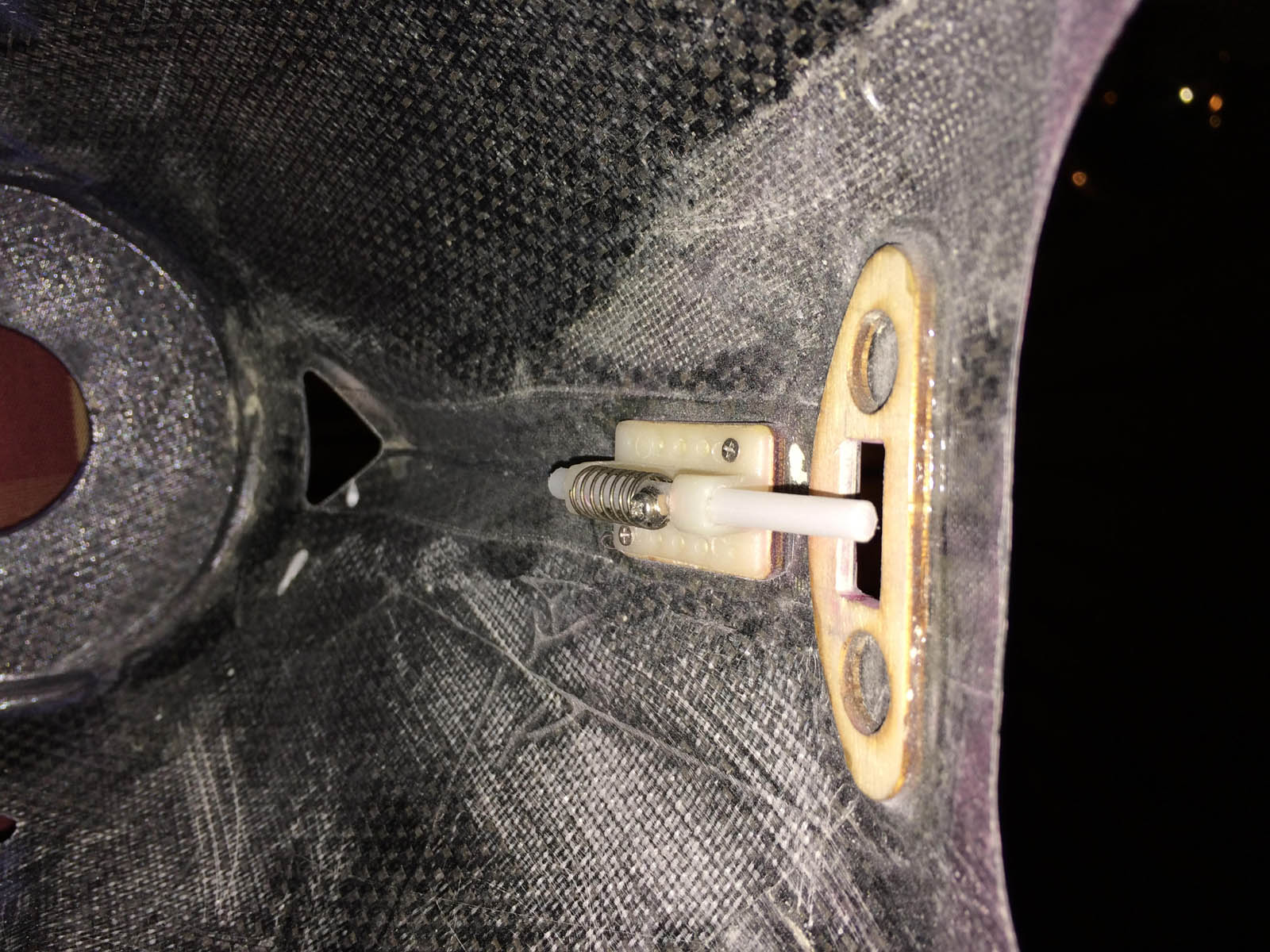
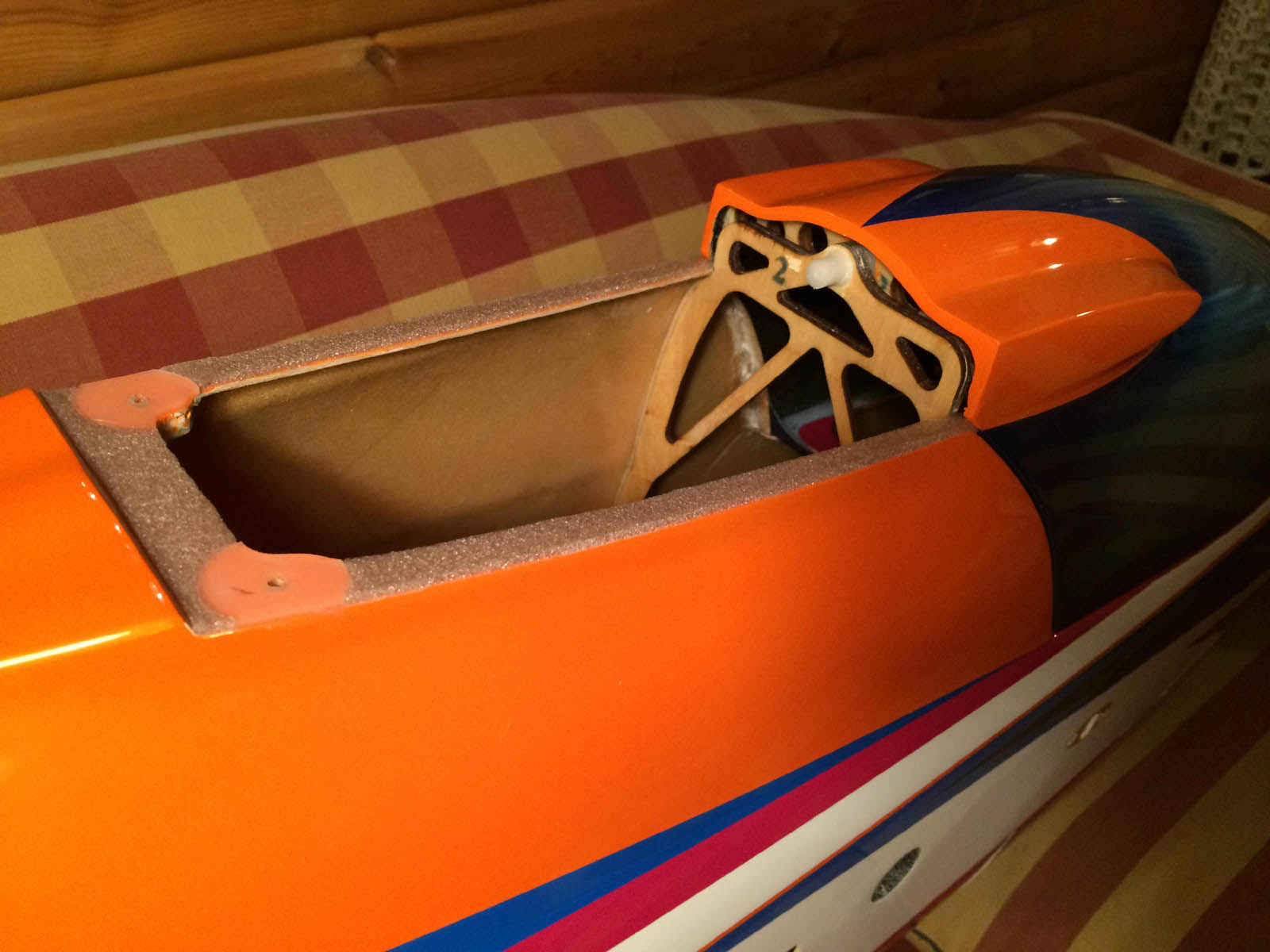
Much carbon in the nose, and nice hatch mechanism for front of canopy.

All the accessories delivered from factory. Note that no main wheel axels and no wheels is shipped with the plane. Tail gear with tailwheel is there but the tailweel seems little fragile and the rubber on the rim is thin.
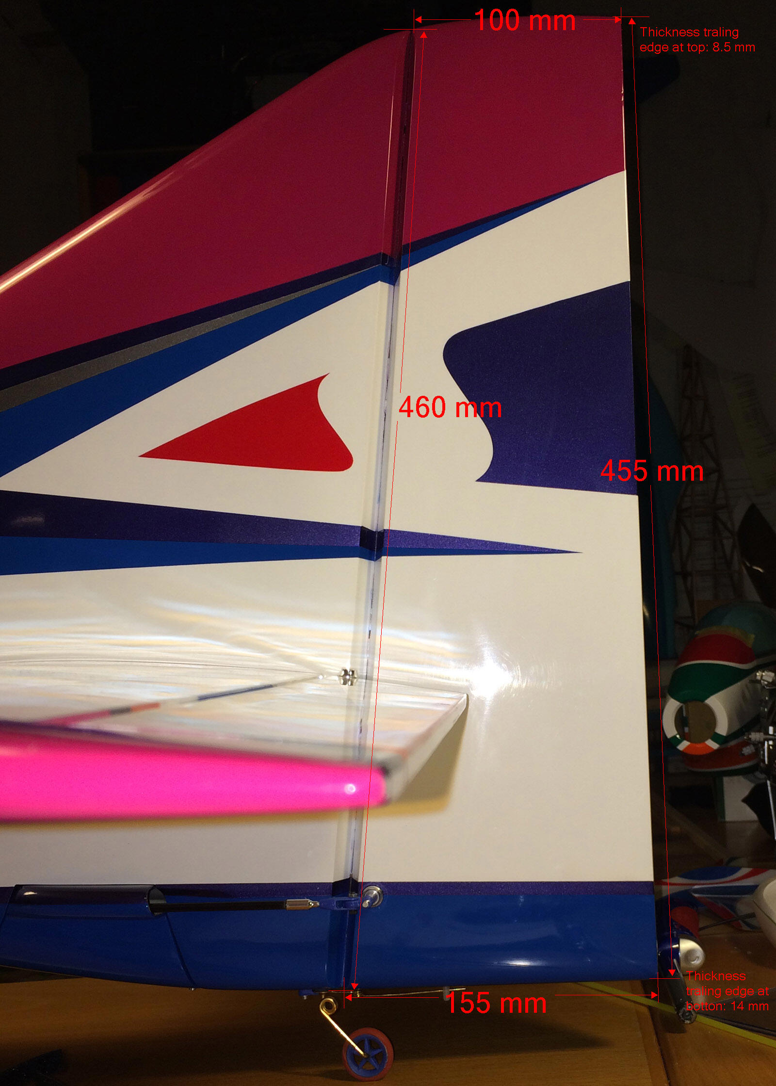
Rudder measured.


One fun comparison: CPLR won WC for the 8th time last year, now with his Galactika. On the Galactika fuselage it is painted 8 gold stars to show this. But on the blue transport cover it is still 7 gold stars. A small detail I discovered some days ago.
See photos.
Note measurments made on wing, stab, T-canard and rudder.
/Bo
Fuselage in all it's shiny glory.
Wing measured, understide wing and wing root profile.
Stab measured, stab underside and stab root profile.
T-canard measured and T-canard mounting points.
Canopy all carbon.
Much carbon in the nose, and nice hatch mechanism for front of canopy.
All the accessories delivered from factory. Note that no main wheel axels and no wheels is shipped with the plane. Tail gear with tailwheel is there but the tailweel seems little fragile and the rubber on the rim is thin.
Rudder measured.
One fun comparison: CPLR won WC for the 8th time last year, now with his Galactika. On the Galactika fuselage it is painted 8 gold stars to show this. But on the blue transport cover it is still 7 gold stars. A small detail I discovered some days ago.
Last edited by bem; 04-29-2016 at 04:15 AM.
04-27-2016, 09:02 AM
#4
Claude,
The problem with buying things like F3A planes in this price range and with transportation from Japan to the dealer (usually I suppose) is that it is very hard to demand a new part like new wing or fuselage in event there is a damage on the plane when it arrive to customer doorstep. The plane is usually built on order for a specific customer.
I suppose in almost all cases for smaller damage we have to settle with a reasonable price reduction. Wolfgang Lorenz of www.f3alorenz.de seems a reasonable guy to deal with in a situation like that. To have a damage on the plane with this build quality and finish, like what was discovered on my plane when unboxing it or Your friends Acuracy bipe wing damage, is never fun.
One problem when repair needs to be done on an Oxai plane is to know the color codes so after repair the damaged area can be painted to as near original as possible using same color code (or as close as possible) as Oxai painted the model with.
I have the European RAL color codes as color charts so I have matched the RAL colors against my Galactika and found these RAL color codes below to be as perfect match as it is possible I think:
White: RAL 120-1 (RAL E3 EFFECT)
Orange: RAL 390-2 (RAL E3 EFFECT)
Red: RAL 450-6 (RAL E3 EFFECT)
Blue: RAL 640-4 (RAL E3 EFFECT)
Red-purpule: RAL 360 40 50 ((RAL D2 DESIGN)
Silver metallic: RAL 830-M (RAL E4 EFFECT, METALLIC)
Purpule metallic: RAL 590-M (RAL E4 EFFECT, METALLIC)
Gold metallic: RAL 290-M (RAL E4 EFFECT, METALLIC)
/Bo

RAL Color Codes charts

White: RAL 120-1 (RAL E3 EFFECT)

Orange: RAL 390-2 (RAL E3 EFFECT)

Red: RAL 450-6 (RAL E3 EFFECT)

Blue: RAL 640-4 (RAL E3 EFFECT)

Red-purpule: RAL 360 40 50 (RAL D2 DESIGN)
Silver metallic: RAL 830-M (RAL E4 EFFECT, METALLIC)

Purpule metallic: RAL 590-M (RAL E4 EFFECT, METALLIC)

Gold metallic: RAL 290-M (RAL E4 EFFECT, METALLIC)
The problem with buying things like F3A planes in this price range and with transportation from Japan to the dealer (usually I suppose) is that it is very hard to demand a new part like new wing or fuselage in event there is a damage on the plane when it arrive to customer doorstep. The plane is usually built on order for a specific customer.
I suppose in almost all cases for smaller damage we have to settle with a reasonable price reduction. Wolfgang Lorenz of www.f3alorenz.de seems a reasonable guy to deal with in a situation like that. To have a damage on the plane with this build quality and finish, like what was discovered on my plane when unboxing it or Your friends Acuracy bipe wing damage, is never fun.
One problem when repair needs to be done on an Oxai plane is to know the color codes so after repair the damaged area can be painted to as near original as possible using same color code (or as close as possible) as Oxai painted the model with.
I have the European RAL color codes as color charts so I have matched the RAL colors against my Galactika and found these RAL color codes below to be as perfect match as it is possible I think:
White: RAL 120-1 (RAL E3 EFFECT)
Orange: RAL 390-2 (RAL E3 EFFECT)
Red: RAL 450-6 (RAL E3 EFFECT)
Blue: RAL 640-4 (RAL E3 EFFECT)
Red-purpule: RAL 360 40 50 ((RAL D2 DESIGN)
Silver metallic: RAL 830-M (RAL E4 EFFECT, METALLIC)
Purpule metallic: RAL 590-M (RAL E4 EFFECT, METALLIC)
Gold metallic: RAL 290-M (RAL E4 EFFECT, METALLIC)
/Bo
RAL Color Codes charts
White: RAL 120-1 (RAL E3 EFFECT)
Orange: RAL 390-2 (RAL E3 EFFECT)
Red: RAL 450-6 (RAL E3 EFFECT)
Blue: RAL 640-4 (RAL E3 EFFECT)
Red-purpule: RAL 360 40 50 (RAL D2 DESIGN)
Silver metallic: RAL 830-M (RAL E4 EFFECT, METALLIC)
Purpule metallic: RAL 590-M (RAL E4 EFFECT, METALLIC)
Gold metallic: RAL 290-M (RAL E4 EFFECT, METALLIC)
Last edited by bem; 04-30-2016 at 12:16 PM.
04-28-2016, 07:17 PM
#6
2. Assembly.
A. Accessories used.
B. Comments on the assembly.
A. Accessories used.
My Galactika was delivered to me February 17 2016 and then I ordered all the accessories I needed to start the assembly.
In end of February and beinning of March most of the ordered accessories had arrived and the assembly could start.
Total time for my assembly was about 1.5 month. Although the model is very much ready for mounting all the things needed in the plane it takes for me often two-three times longer time to mount various things in the plane then expected.
These accessories was choosen:
1. Motor: Hacker Q80-14XS F3A, with carbon motor mount and carbon back support.
(Supplier: www.f3alorenz.de)
2. ESC: Jeti/Hacker MasterMezon 90 with BEC.
(Supplier: www.f3alorenz.de)
3. Servos, all Futaba S.BUS2, High Voltage, Brushless:
Ailerion - BLS174SV x 2
Elevator - BLS173SV x 2
Rudder - BLS171SV
(Supplier: www.rcjapan.net)
4. Receiver: Futaba R6308SBT (FASST with telemetry and S.BUS2) together with my old 14MZ TX and Robbe/Futaba external Telemetry Box F1666.
(Supplier: local hobbyshop in my country)
5. Robbe/Futaba F1678 150A current sensor, FASSTest, S.BUS2.
(Supplier: from Robbe in Germany when they still was in business early 2015, can now
still be bought from several online shops in Germany)
6. Scorpion Backup Guard, 2 cell 500 mAh LiPo.
(Supplier: local hobbyshop in my country)
7. ThunderPower ProLite+ Power Series 5000 mAh 2 x 5 cell 25C LiPo.
(Supplier: ThunderPower when they had 50% discount)
8. Falcon 21 x 14 V2 Electric carbon propeller.
(Supplier: www.f3alorenz.de)
9. Falcon 82 millimeter Electric vented carbon spinner.
(Supplier: www.f3alorenz.de)
10-11. Main wheel axles, Seacraft 4 x 21 millimeter.
(Supplier: www.f3aunlimited.com)
Dubro SuperLite 70 mm (2-3/4") wheels.
(Supplier: www3.towerhobbies.com)
12. Servo lead with fixed socket (for wing and stab servos quick connect to fuselage side), Robbe F1639.
(Supplier: from Robbe in Germany when they still was in business early 2015)
13. S.BUS Hub 4 sockets and 6 sockets (4 socket in tail and 6 socket in front of fuselage).
14. Futaba external voltage connector with cable, CA-RVIN-700.
(Supplier: local hobbyshop in my country)
15. Robbe metal blue servoarm 15 mm, 1-8512, for the two elevators servos.
(Supplier: from Robbe in Germany when they still was in business early 2015)
16. Secraft Floating pad No 1, 10 mm diameter 1 mm thick, for canopy padding.
(Supplier: www.f3aunlimited.com)
17. Carbon-Herex-Carbon laminate, for battery tray, S.BUS and ESC mounting plates.
(Supplier: www.f3alorenz.de)
First task was to mount the electric motor I selected to use.
Then I mounted the landing gear.
After that I mounted the servos, linkages and the stab.
At the same time all the servos was mounted I learned more about S.BUS2 since only SBUS.2 was going to be used in this plane (first time for me with only S.BUS2).
S.BUS hubs, one in tail and one under wing tube on fuselage floor, was mounted.
Then the Electronic Speed Controller (ESC) with the S.BUS2 current sensor was mounted next.
Receiver and a Backup Guard (Scorpion) was finally decided where to mount.
One of the last thing that I made was the flight battery tray for the 10 cell LiPo, after checking Center of Garvity with the battery in fuselage.
More on this in "B. Comments on the assembly." that I will post next, in a few days.
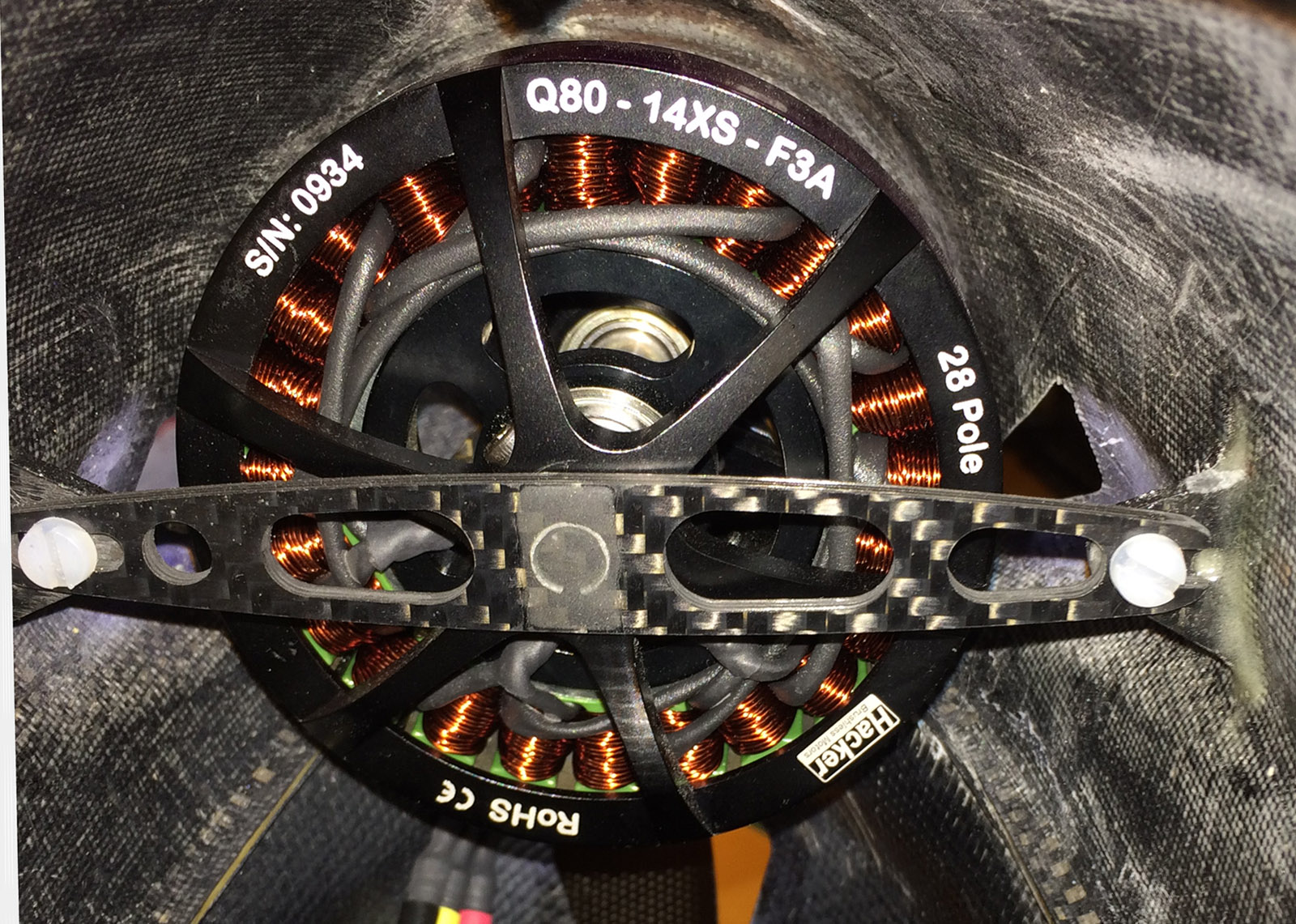
Hacker Q80-14XS F3A. Very nice motor, I have the same motor in my Sebart MythoS Pro.
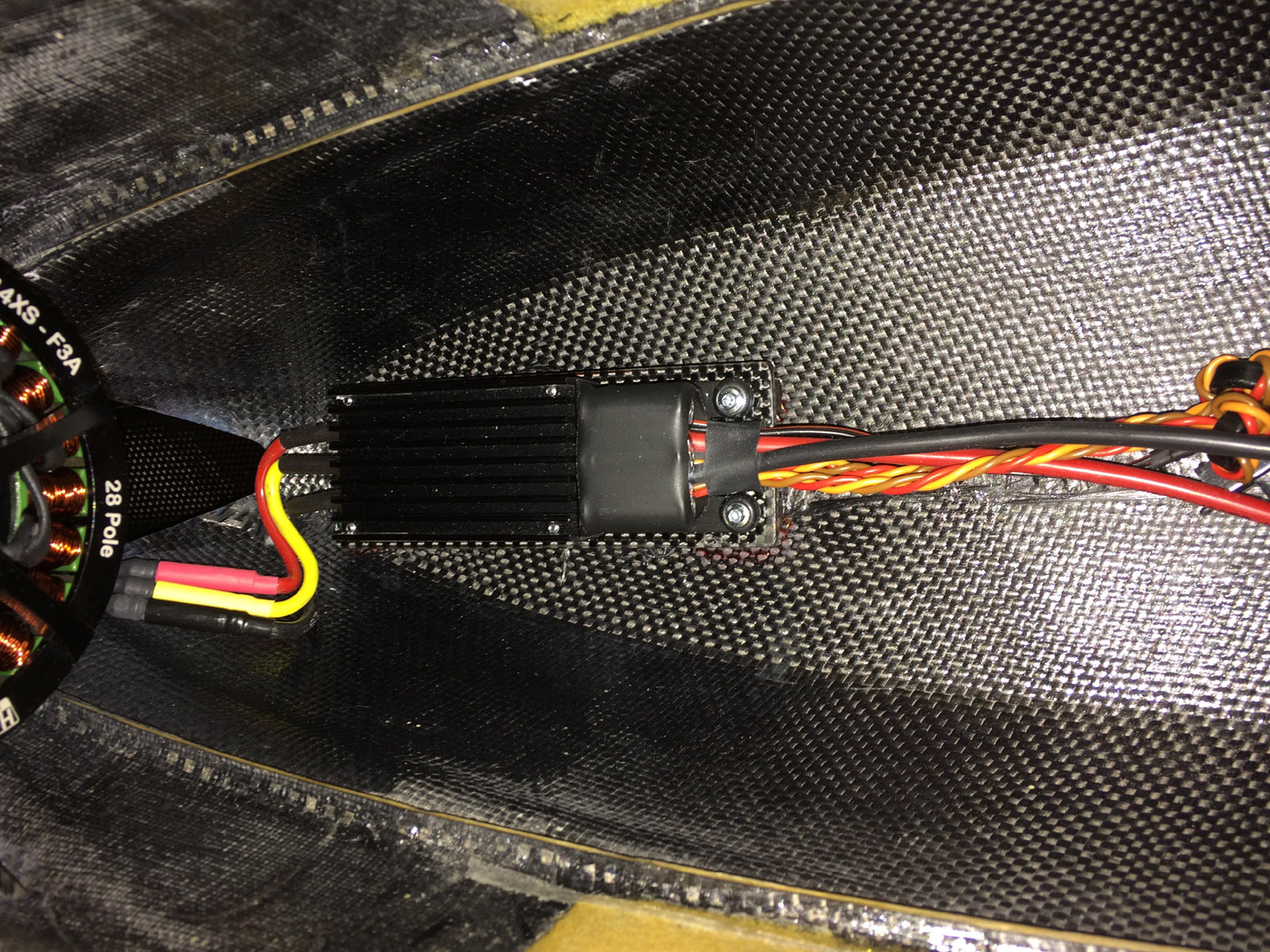
Jeti/Hacker Master Mezon 90 ESC with BEC (I use the BEC). A very good ESC in my opinion but on the heavy side with weight 140 grams. Easy to adjust with Jeti Box and You can also see ESC log efter flight. I have a Master Mezon also in my MythoS Pro, used for 2 seasons without any problem in that plane.

Futaba S.BUS2, High Voltage, Brushless servos: Ailerion - BLS174SV x 2, Elevator - BLS173SV x 2, Rudder - BLS171SV. The aileron servos are on the heavy side with 53 grams each. Rudder servo is 48 grams and each elevator servo is 28 grams. All S.BUS2 in the plane is new to me, I hesitated a little before I moved over to all S.BUS2 but it seems to work fine so far. One need to know each servo ID if one want to make changes to the servo settings with Futaba PC Link Programmer application (I tested that and it worked fine to set channel number on each servo and a bunch of other changes can also be made to the servo if one want).
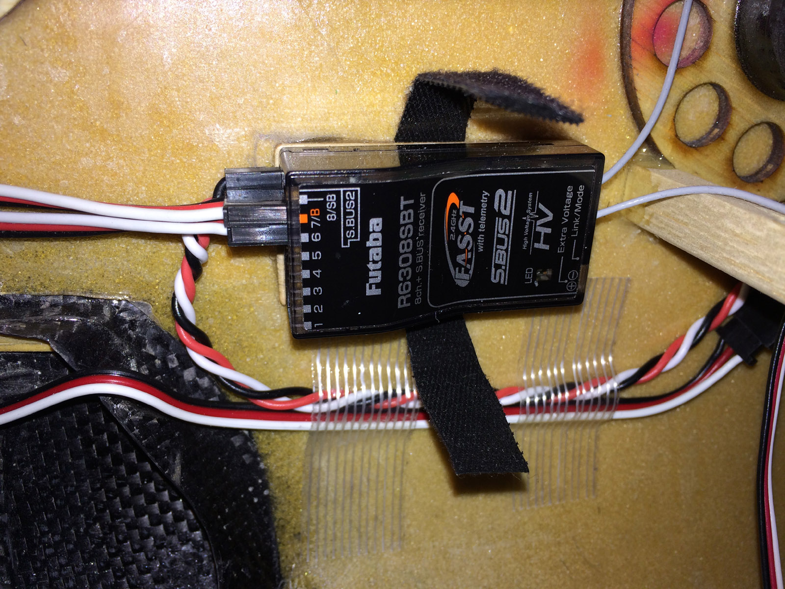
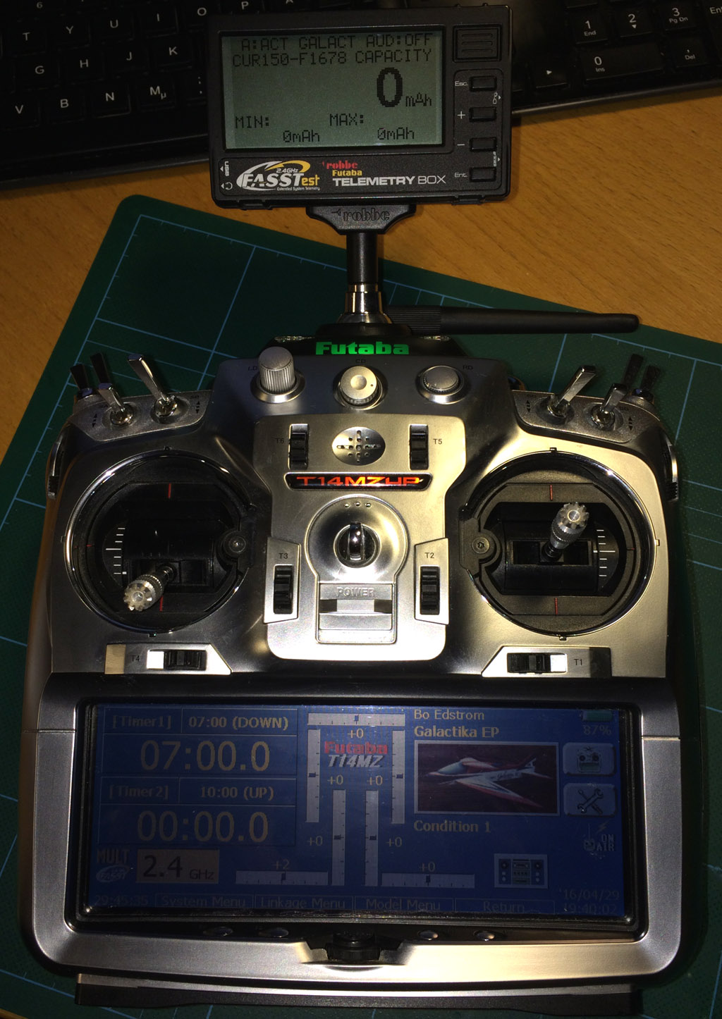
Receiver: Futaba R6308SBT (FASST with telemetry and S.BUS2, weight 11 grams), the only Futaba receiver that can be used with Futaba FASST radio, like my 14MZ that lack telemetry from factory, and one want to have Futaba telemetry with Futaba/Robbe external Telemetry Box.

Robbe/Futaba F1678 150A current sensor, FASSTest, S.BUS2. Very nice but discontinued today (but can still be found in Germany mostly). Used it in my previous F3A plane for two seasons and no problem encountered, so I continue with same in my Galactika. Weight 19 grams.

Scorpion Backup Guard, a nice backup battery (37 grams) that is connected to receiver and jumps in automatically if voltage is 5 volts or below. Used it in my previous F3A plane for two seasons and no problem encountered, so I continue with same in my Galactika.

ThunderPower ProLite+ Power Series 5000 mAh 2 x 5 cell 25C LiPo, 1150 gram each pack with the bullet connectors mounted. I had same ThunderPower but G8 ProLite+ (not Power Series) before for two seasons in MythoS Pro and they worked fine so I continue with ThunderPower brand in Galactika also.

Falcon 21 x 14 V2 Electric carbon propeller. Very nice and light (40.4 grams) with good performance in the Galactika.

Falcon 82 millimeter Electric vented carbon spinner, very light at 22.8 grams.

Main wheel axles, Seacraft 4 x 21 millimeter, weight for both axles 6.8 grams. Dubro SuperLite 70 mm (2-3/4") wheels, 29.6 grams for both.

Servo lead with fixed socket (for wing and stab servos quick connect to fuselage side), Robbe F1639 (discontinued).

Futaba S.BUS Hub, 6 sockets in fuselage and 4 sockets in tail. Servo connector secured to the tail hub connectors with dental floss.
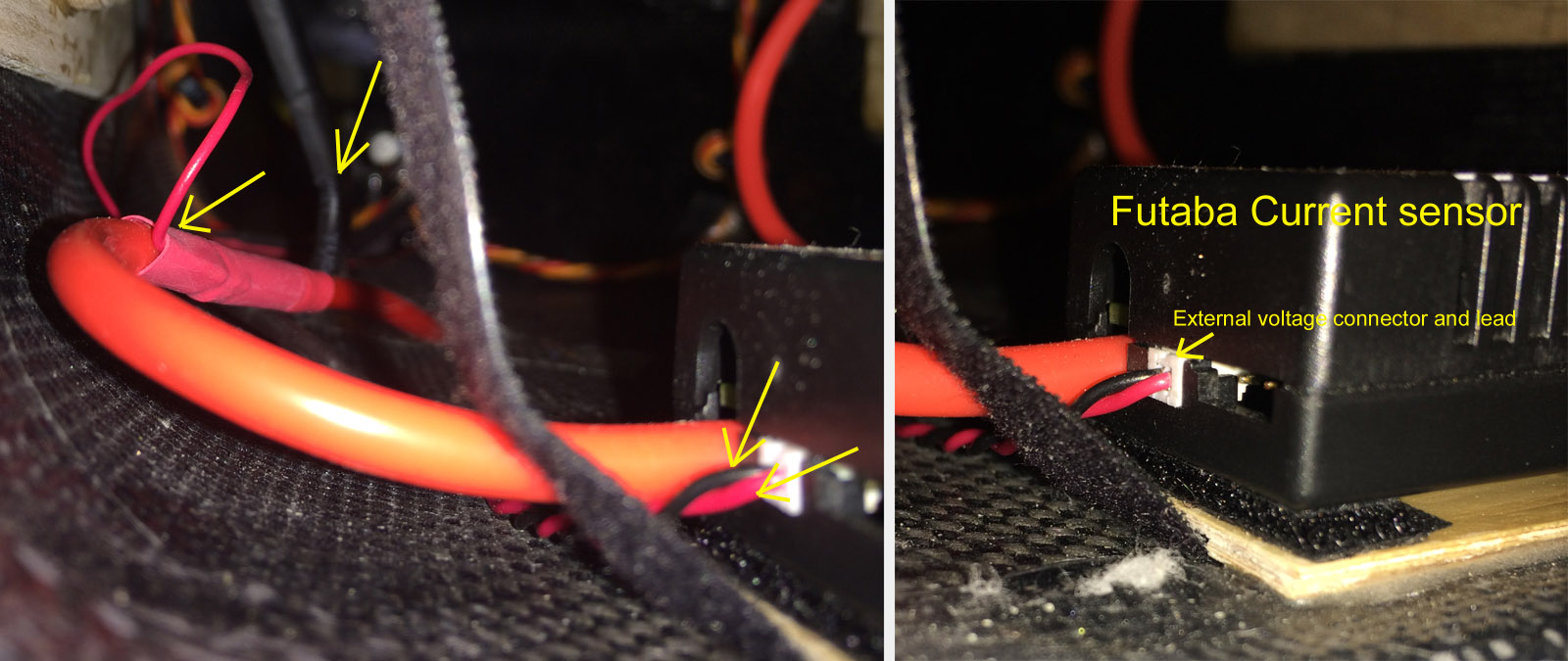
Futaba external voltage connector with cable, CA-RVIN-700, connected to the Futaba/Robbe current sensor and to flight battery cable leads.

Robbe metal blue servoarm 15 mm, 1-8512 (discontinued), for the two elevators servos.

Secraft Floating pad No 1, 10 mm diameter 1 mm thick, for canopy padding. To avoid craping/wearing and rattle.

Carbon-Herex-Carbon laminate, for battery tray, S.BUS and ESC mounting plates. Very light and strong. On the hubplate in front of fuselage I have made an extra place with velcro for future use if needed.
/Bo
A. Accessories used.
B. Comments on the assembly.
A. Accessories used.
My Galactika was delivered to me February 17 2016 and then I ordered all the accessories I needed to start the assembly.
In end of February and beinning of March most of the ordered accessories had arrived and the assembly could start.
Total time for my assembly was about 1.5 month. Although the model is very much ready for mounting all the things needed in the plane it takes for me often two-three times longer time to mount various things in the plane then expected.
These accessories was choosen:
1. Motor: Hacker Q80-14XS F3A, with carbon motor mount and carbon back support.
(Supplier: www.f3alorenz.de)
2. ESC: Jeti/Hacker MasterMezon 90 with BEC.
(Supplier: www.f3alorenz.de)
3. Servos, all Futaba S.BUS2, High Voltage, Brushless:
Ailerion - BLS174SV x 2
Elevator - BLS173SV x 2
Rudder - BLS171SV
(Supplier: www.rcjapan.net)
4. Receiver: Futaba R6308SBT (FASST with telemetry and S.BUS2) together with my old 14MZ TX and Robbe/Futaba external Telemetry Box F1666.
(Supplier: local hobbyshop in my country)
5. Robbe/Futaba F1678 150A current sensor, FASSTest, S.BUS2.
(Supplier: from Robbe in Germany when they still was in business early 2015, can now
still be bought from several online shops in Germany)
6. Scorpion Backup Guard, 2 cell 500 mAh LiPo.
(Supplier: local hobbyshop in my country)
7. ThunderPower ProLite+ Power Series 5000 mAh 2 x 5 cell 25C LiPo.
(Supplier: ThunderPower when they had 50% discount)
8. Falcon 21 x 14 V2 Electric carbon propeller.
(Supplier: www.f3alorenz.de)
9. Falcon 82 millimeter Electric vented carbon spinner.
(Supplier: www.f3alorenz.de)
10-11. Main wheel axles, Seacraft 4 x 21 millimeter.
(Supplier: www.f3aunlimited.com)
Dubro SuperLite 70 mm (2-3/4") wheels.
(Supplier: www3.towerhobbies.com)
12. Servo lead with fixed socket (for wing and stab servos quick connect to fuselage side), Robbe F1639.
(Supplier: from Robbe in Germany when they still was in business early 2015)
13. S.BUS Hub 4 sockets and 6 sockets (4 socket in tail and 6 socket in front of fuselage).
14. Futaba external voltage connector with cable, CA-RVIN-700.
(Supplier: local hobbyshop in my country)
15. Robbe metal blue servoarm 15 mm, 1-8512, for the two elevators servos.
(Supplier: from Robbe in Germany when they still was in business early 2015)
16. Secraft Floating pad No 1, 10 mm diameter 1 mm thick, for canopy padding.
(Supplier: www.f3aunlimited.com)
17. Carbon-Herex-Carbon laminate, for battery tray, S.BUS and ESC mounting plates.
(Supplier: www.f3alorenz.de)
First task was to mount the electric motor I selected to use.
Then I mounted the landing gear.
After that I mounted the servos, linkages and the stab.
At the same time all the servos was mounted I learned more about S.BUS2 since only SBUS.2 was going to be used in this plane (first time for me with only S.BUS2).
S.BUS hubs, one in tail and one under wing tube on fuselage floor, was mounted.
Then the Electronic Speed Controller (ESC) with the S.BUS2 current sensor was mounted next.
Receiver and a Backup Guard (Scorpion) was finally decided where to mount.
One of the last thing that I made was the flight battery tray for the 10 cell LiPo, after checking Center of Garvity with the battery in fuselage.
More on this in "B. Comments on the assembly." that I will post next, in a few days.
Hacker Q80-14XS F3A. Very nice motor, I have the same motor in my Sebart MythoS Pro.
Jeti/Hacker Master Mezon 90 ESC with BEC (I use the BEC). A very good ESC in my opinion but on the heavy side with weight 140 grams. Easy to adjust with Jeti Box and You can also see ESC log efter flight. I have a Master Mezon also in my MythoS Pro, used for 2 seasons without any problem in that plane.
Futaba S.BUS2, High Voltage, Brushless servos: Ailerion - BLS174SV x 2, Elevator - BLS173SV x 2, Rudder - BLS171SV. The aileron servos are on the heavy side with 53 grams each. Rudder servo is 48 grams and each elevator servo is 28 grams. All S.BUS2 in the plane is new to me, I hesitated a little before I moved over to all S.BUS2 but it seems to work fine so far. One need to know each servo ID if one want to make changes to the servo settings with Futaba PC Link Programmer application (I tested that and it worked fine to set channel number on each servo and a bunch of other changes can also be made to the servo if one want).
Receiver: Futaba R6308SBT (FASST with telemetry and S.BUS2, weight 11 grams), the only Futaba receiver that can be used with Futaba FASST radio, like my 14MZ that lack telemetry from factory, and one want to have Futaba telemetry with Futaba/Robbe external Telemetry Box.
Robbe/Futaba F1678 150A current sensor, FASSTest, S.BUS2. Very nice but discontinued today (but can still be found in Germany mostly). Used it in my previous F3A plane for two seasons and no problem encountered, so I continue with same in my Galactika. Weight 19 grams.
Scorpion Backup Guard, a nice backup battery (37 grams) that is connected to receiver and jumps in automatically if voltage is 5 volts or below. Used it in my previous F3A plane for two seasons and no problem encountered, so I continue with same in my Galactika.
ThunderPower ProLite+ Power Series 5000 mAh 2 x 5 cell 25C LiPo, 1150 gram each pack with the bullet connectors mounted. I had same ThunderPower but G8 ProLite+ (not Power Series) before for two seasons in MythoS Pro and they worked fine so I continue with ThunderPower brand in Galactika also.
Falcon 21 x 14 V2 Electric carbon propeller. Very nice and light (40.4 grams) with good performance in the Galactika.
Falcon 82 millimeter Electric vented carbon spinner, very light at 22.8 grams.
Main wheel axles, Seacraft 4 x 21 millimeter, weight for both axles 6.8 grams. Dubro SuperLite 70 mm (2-3/4") wheels, 29.6 grams for both.
Servo lead with fixed socket (for wing and stab servos quick connect to fuselage side), Robbe F1639 (discontinued).
Futaba S.BUS Hub, 6 sockets in fuselage and 4 sockets in tail. Servo connector secured to the tail hub connectors with dental floss.
Futaba external voltage connector with cable, CA-RVIN-700, connected to the Futaba/Robbe current sensor and to flight battery cable leads.
Robbe metal blue servoarm 15 mm, 1-8512 (discontinued), for the two elevators servos.
Secraft Floating pad No 1, 10 mm diameter 1 mm thick, for canopy padding. To avoid craping/wearing and rattle.
Carbon-Herex-Carbon laminate, for battery tray, S.BUS and ESC mounting plates. Very light and strong. On the hubplate in front of fuselage I have made an extra place with velcro for future use if needed.
/Bo
Last edited by bem; 05-09-2016 at 03:30 AM.
04-29-2016, 12:48 AM
#7
No I did not but I thought about it several times. I said to myself that I can not do anyting about the weight on the empty plane itself so it was never done unfortunately.
- The T-canard is easy to weight so I can do that.
- Wings without servos and linkages I can weight and get empty weight on them if You want, it is easy.
- To get the stabs empty weight I have to remove the servos and linkage plus the elevator horn and maybe I can't get the elevator horn off because I think I had a drop of CA glue in the threads, but I can get the weight on the stabs without servos and linkages(except elevator horn).
- The fuselage empty weight is impossible to get now when all is installed, leads in place and mounting plates, strengthening of landing gear plates is already done,
I will see what I can do. It seems to be bad weather this weekend here so maybe I can do some "empty" weighing.
It would for sure have been nice to have each part empty weight on precisely my individual Galactica, left-right wing, left-right stab, T-canard, fuselage without landing gear and that way get the total empty weight also.
Oxai has still on their homepage published the specification on Galactika and they list empty weight on Galactika EP (that I have) to 2300 grams but that is without landing gear and the Oxai accessories - see post #2 above what accessories is shipped with the plane:
Oxai Galactika specifications.
/Bo
Last edited by bem; 04-29-2016 at 02:21 AM.
04-29-2016, 07:05 AM
#8

Bo,
No need to disassemble the plane because of this. I'm just curious and can very well compare the assembled weights. It is quite easy to estimate the wing panel and elevator empty weighs from assembled weights since you listed the servos.
***Risto***
No need to disassemble the plane because of this. I'm just curious and can very well compare the assembled weights. It is quite easy to estimate the wing panel and elevator empty weighs from assembled weights since you listed the servos.
***Risto***
04-30-2016, 11:57 AM
#9
B. Comments on the assembly.
a) Mounting the electric motor.
b) Mounting landing gear.
c) Mounting servos, linkages and the stab.
d) Mounting S.BUS hubs, one in tail and one under wing tube on fuselage floor.
e) Mounting Electronic Speed Controller (ESC) with the S.BUS2 current sensor.
f) Mounting receiver and Scorpion Backup Guard.
g) Flight LiPo battery tray for the 10 cell LiPo.
h) Galactika transportation cover.
a) Mounting the electric motor.
Hacker Q80-14XS F3A was choosen for my Galactika. It is a very nice electric motor.
I have used same motor in Sebart MythoS Pro for 2 seasons without any problem.
Specifications:
Powerange: Max. 2800W (15 sec.)
Idle Current @ 8,4V: 0,9 A
Resistance (Ri): 0,025 Ohm
RPM/Volt (kv): 209 U/min-1
Weight: 528g
Diameter: 88,5 mm
Length: 69 mm
Shaft diameter: 8 mm
Recommeded Timing: 25�
Switching Frequenzy: 8 kHz (according to manual and Hacker German hompage)
16 kHz (according to Hacker English homepage), I use 8 kHz
A carbon motor mount and a carbon rear support was bought from f3alorenz.de and what I needed to do myself was proper plywood distance so the motor got aligned with the nosering on fuselage with a distance of 1.8 millimter between spinner backplate and nosering.
I made the plywood spacers of hard high quality multilayer plywood that I shaped so as little material was needed as possible to save some weight but not to much so it became weak.
I enlarged with a Dremel the nosering center hole to help cooling the motor etc better. The 4 screws was countersunk in nosering after checking that the 82 mm Falcon vented electric carbon spinner was aligned properly at nosering.
After the spacers was glued to the carbon motor mount the spacers was gradually grinded down with fine wet sandpaper on a table so the motorshaft was exactly perpendicular both horizontally and vertically. I checked with feeler guage that it was finally exactly 1.8 mm around the nosering to the spinner backplate. I had the motor in and out of fuselage for this fine adjustment maybe 10 times.
The carbon motor mount was bought from f3alorenz.de and it has item no 2302.
I mounted also a rear support for the Q80-14XS, it is made of carbon and has a center metal tube (that is pressed in and glued to the rear support) that goes in to the rear ball bearing on the motor and it fits perfectly.
I have the same solution on my MythoS Pro. Although the rear support is fastened with nylon screws, that is shipped with the rear support, it is enough strenght.
Small carbon "ears" for fastening of the rear carbon support was glued on fuselage inner side with slow curing epoxy mixed with West System 402 Micro fibres so the epoxy did not flow. The carbon rear support was bought from f3alorenz.de also and item no was 381 (discontinued now).
I have prepared so i can use 0.1 or 0.2 mm titanium shims (washers) between the carbon motor mount and nosering inside to change angle on motor shaft. I doubt i need to change that.
Later I found out that RS -Ralph Schweizer Modelltechnik- has same carbon motor mount with nice aluminium spacers of different thickness and shims.
If I had known that before I started to mount the motor I would have tried these spacers to save some time. It is this, at the top of page:
http://www.ralphschweizer.com/neueprodukte.htm
Mounting of the motor was the most time consuming part of the assembly for me and requires the most precision. I spent almost one week of evenings, a couple hours each evening, before I was satisfied and had finished mounting the motor.
Hacker Q80-14XS F3A fits very well in the Galactika nose. No problem at all was encountered mounting it in my Galactika.
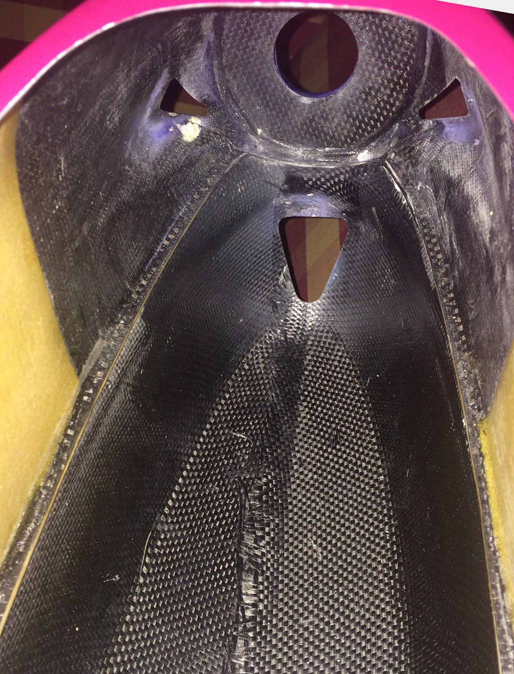
Galactika nose waiting for a Hacker Q80-14XS F3A motor.
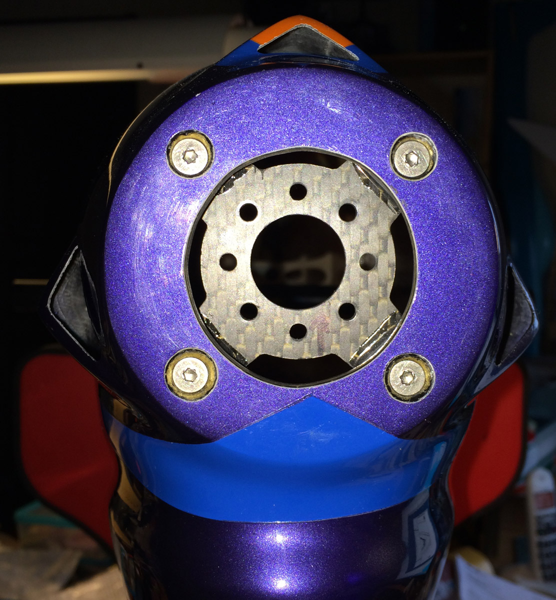
Carbon motor mount mounted and screws countersunk in nosering. Nosering center hole has been enlarged here to give better cooling.

Plywwod spacers made and glued to the carbon motor mount. All plywood that is exposed was brushed with a thin layer of epoxy to withstand moisture.

Carbon motor mount testmounted inside fuselage with 25 mm M4 screws, later replaced with lighter titanium screws and with lock nuts.

Hacker Q80-14XS F3A in place in my Galactika with the rear carbon support.
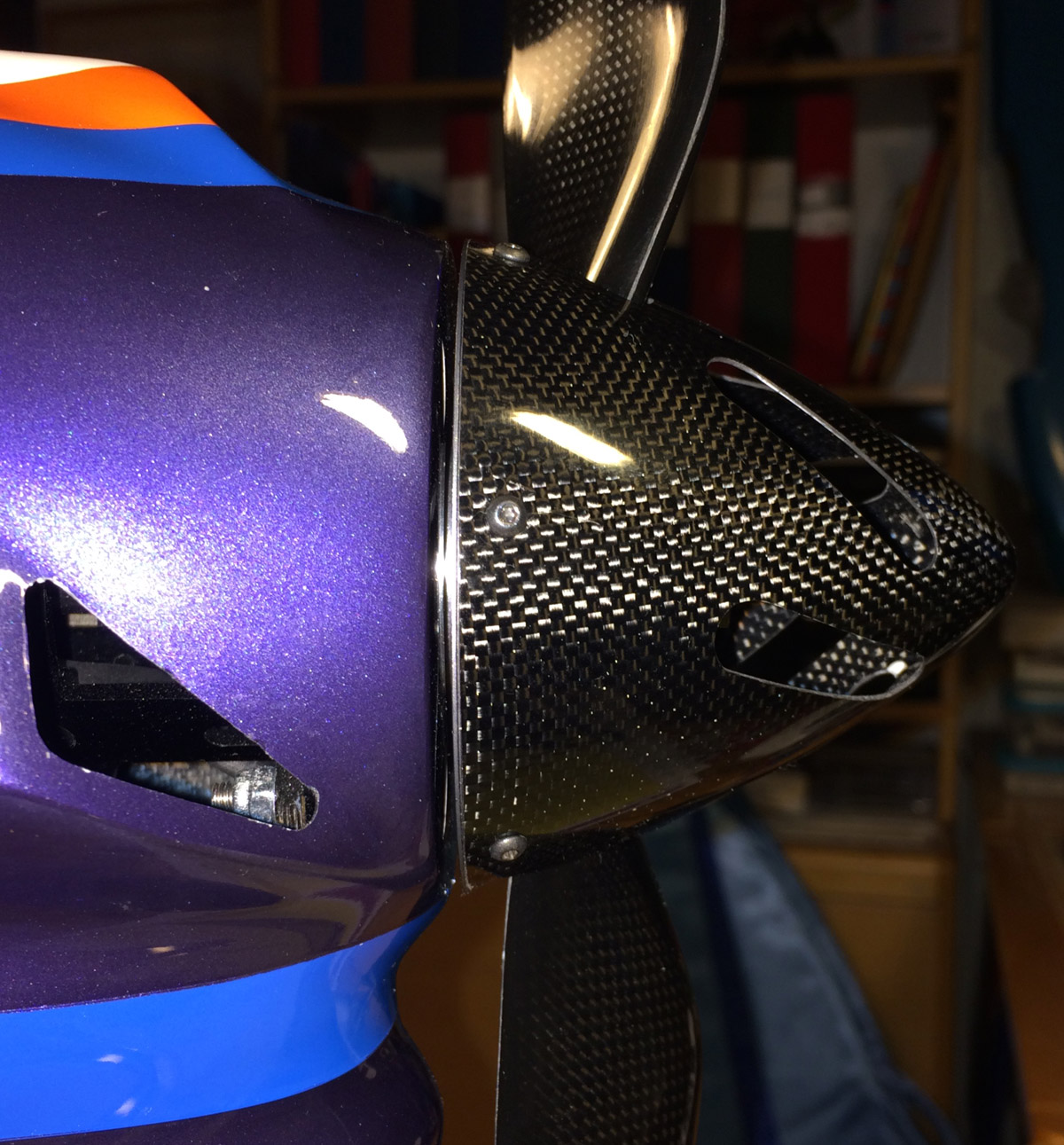
Falcon 82 mm electric vented spinner mounted to check alignment againts nosering - all looking good. It is 1.8 mm space between backplate of spinner and nosering making room for any future change of motor angle.

Spinner front view.
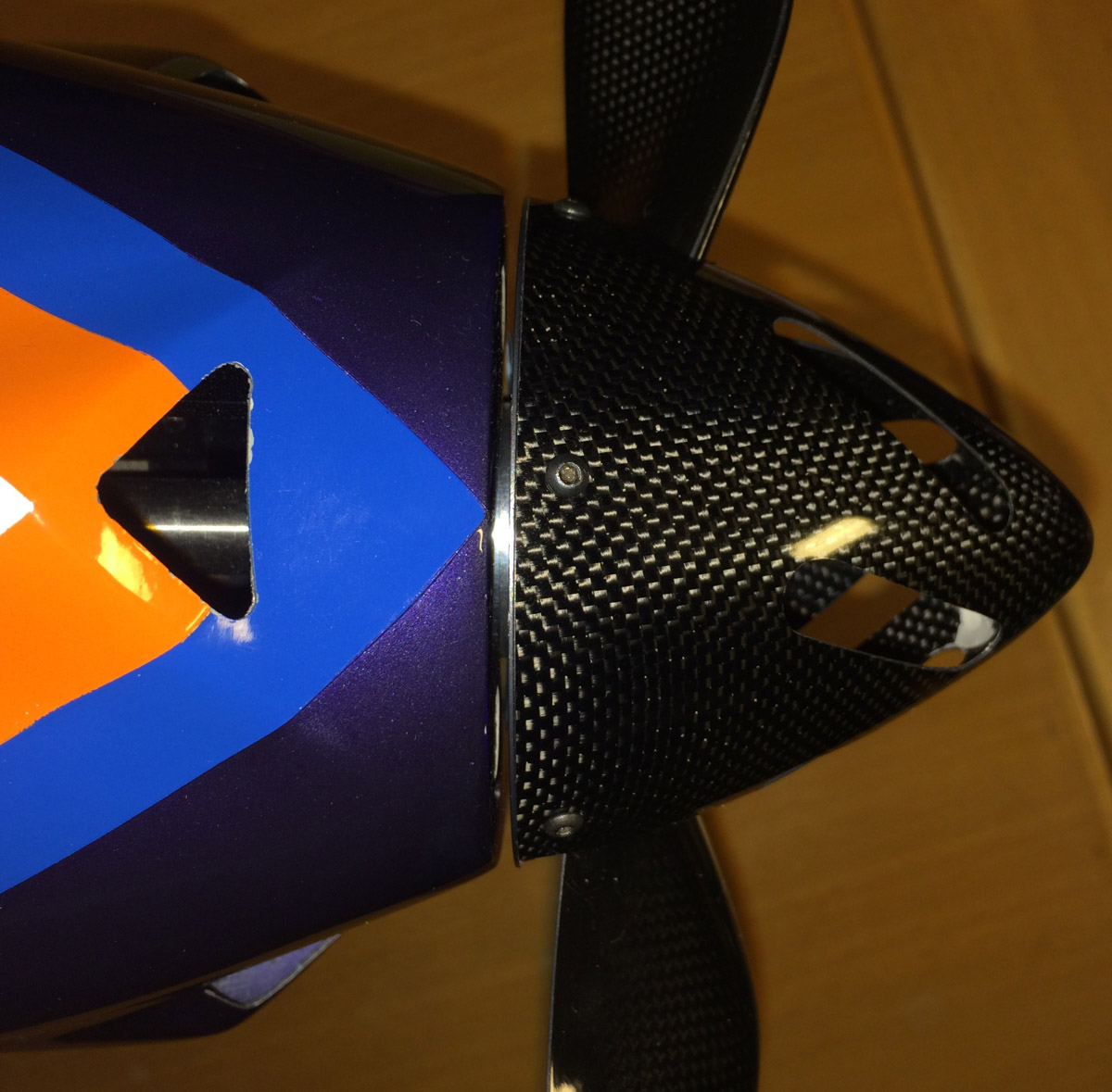
Spinner top view.
/Bo
a) Mounting the electric motor.
b) Mounting landing gear.
c) Mounting servos, linkages and the stab.
d) Mounting S.BUS hubs, one in tail and one under wing tube on fuselage floor.
e) Mounting Electronic Speed Controller (ESC) with the S.BUS2 current sensor.
f) Mounting receiver and Scorpion Backup Guard.
g) Flight LiPo battery tray for the 10 cell LiPo.
h) Galactika transportation cover.
a) Mounting the electric motor.
Hacker Q80-14XS F3A was choosen for my Galactika. It is a very nice electric motor.
I have used same motor in Sebart MythoS Pro for 2 seasons without any problem.
Specifications:
Powerange: Max. 2800W (15 sec.)
Idle Current @ 8,4V: 0,9 A
Resistance (Ri): 0,025 Ohm
RPM/Volt (kv): 209 U/min-1
Weight: 528g
Diameter: 88,5 mm
Length: 69 mm
Shaft diameter: 8 mm
Recommeded Timing: 25�
Switching Frequenzy: 8 kHz (according to manual and Hacker German hompage)
16 kHz (according to Hacker English homepage), I use 8 kHz
A carbon motor mount and a carbon rear support was bought from f3alorenz.de and what I needed to do myself was proper plywood distance so the motor got aligned with the nosering on fuselage with a distance of 1.8 millimter between spinner backplate and nosering.
I made the plywood spacers of hard high quality multilayer plywood that I shaped so as little material was needed as possible to save some weight but not to much so it became weak.
I enlarged with a Dremel the nosering center hole to help cooling the motor etc better. The 4 screws was countersunk in nosering after checking that the 82 mm Falcon vented electric carbon spinner was aligned properly at nosering.
After the spacers was glued to the carbon motor mount the spacers was gradually grinded down with fine wet sandpaper on a table so the motorshaft was exactly perpendicular both horizontally and vertically. I checked with feeler guage that it was finally exactly 1.8 mm around the nosering to the spinner backplate. I had the motor in and out of fuselage for this fine adjustment maybe 10 times.
The carbon motor mount was bought from f3alorenz.de and it has item no 2302.
I mounted also a rear support for the Q80-14XS, it is made of carbon and has a center metal tube (that is pressed in and glued to the rear support) that goes in to the rear ball bearing on the motor and it fits perfectly.
I have the same solution on my MythoS Pro. Although the rear support is fastened with nylon screws, that is shipped with the rear support, it is enough strenght.
Small carbon "ears" for fastening of the rear carbon support was glued on fuselage inner side with slow curing epoxy mixed with West System 402 Micro fibres so the epoxy did not flow. The carbon rear support was bought from f3alorenz.de also and item no was 381 (discontinued now).
I have prepared so i can use 0.1 or 0.2 mm titanium shims (washers) between the carbon motor mount and nosering inside to change angle on motor shaft. I doubt i need to change that.
Later I found out that RS -Ralph Schweizer Modelltechnik- has same carbon motor mount with nice aluminium spacers of different thickness and shims.
If I had known that before I started to mount the motor I would have tried these spacers to save some time. It is this, at the top of page:
http://www.ralphschweizer.com/neueprodukte.htm
Mounting of the motor was the most time consuming part of the assembly for me and requires the most precision. I spent almost one week of evenings, a couple hours each evening, before I was satisfied and had finished mounting the motor.
Hacker Q80-14XS F3A fits very well in the Galactika nose. No problem at all was encountered mounting it in my Galactika.
Galactika nose waiting for a Hacker Q80-14XS F3A motor.
Carbon motor mount mounted and screws countersunk in nosering. Nosering center hole has been enlarged here to give better cooling.
Plywwod spacers made and glued to the carbon motor mount. All plywood that is exposed was brushed with a thin layer of epoxy to withstand moisture.
Carbon motor mount testmounted inside fuselage with 25 mm M4 screws, later replaced with lighter titanium screws and with lock nuts.
Hacker Q80-14XS F3A in place in my Galactika with the rear carbon support.
Falcon 82 mm electric vented spinner mounted to check alignment againts nosering - all looking good. It is 1.8 mm space between backplate of spinner and nosering making room for any future change of motor angle.
Spinner front view.
Spinner top view.
/Bo
Last edited by bem; 05-22-2016 at 03:10 PM.
04-30-2016, 01:28 PM
#10
b) Mounting landing gear.
At first I thought that this task would be easy and go rather quick. Oboy I was wrong.
To get the bowed (both side and front view) landing gear legs properly alligned I had to use a 4 mm carbon tube through the wheel axles so I had a reference line to get the legs and wheel axles aligned seen from above, perpendiculer to fuselage centerline.
I used the wing carbon tube and aimed to get the 4 mm carbon tube parallel to that. Using clamps to hold the landing gear against the landing gear mounting plate in fuselage (already in place from factory) I was finally satisfied and drilled the 3 holes in each gear legs mounting plate through the landing gear plywood
mounting plate. So far so good.
I had some new Secraft aluminium wood lock M4 nuts that I used on underside landing gear plate:
http://www.secraft.net/shop/step1.ph...20090803051116
This was a big misstake when using steel hex screws. When I had mounted every screws so landing gear was mounted as it should I wanted to take away the landing gear when I was working with the fuselage on a stand with other things. Then one of the screws got stuck on the thread and impossible to turn loose. Somehow I got galling despite the Secraft aluminium wood lock nut has a steel nut inside according to Secraft homepage.
I had to spend a whole evening gridning down the head of the steel hex screw with a Dremel and then I was able to bend away the wood lock nuts from underside.
I changed to steel wood luck nuts instead but then I got an unforeseen problem with one of these screws. One thread was defect and when I tighted the hex screws the thread was so weak in one of wood lock nuts that the screw just turned without possibility to fasten. I could not unscrew the screw either (that was recessed in Secraft washer).
Once again I had to use my Dremel... man, now my patience with the landing gear was almost gone.
Finally I replace the defect wood lock nut and the gear was permanetly fastened with total 6 M4 25 mm hex screws with Secraft 15 mm blue aluminium washers and my Galactika was on it's own feet for the first time.
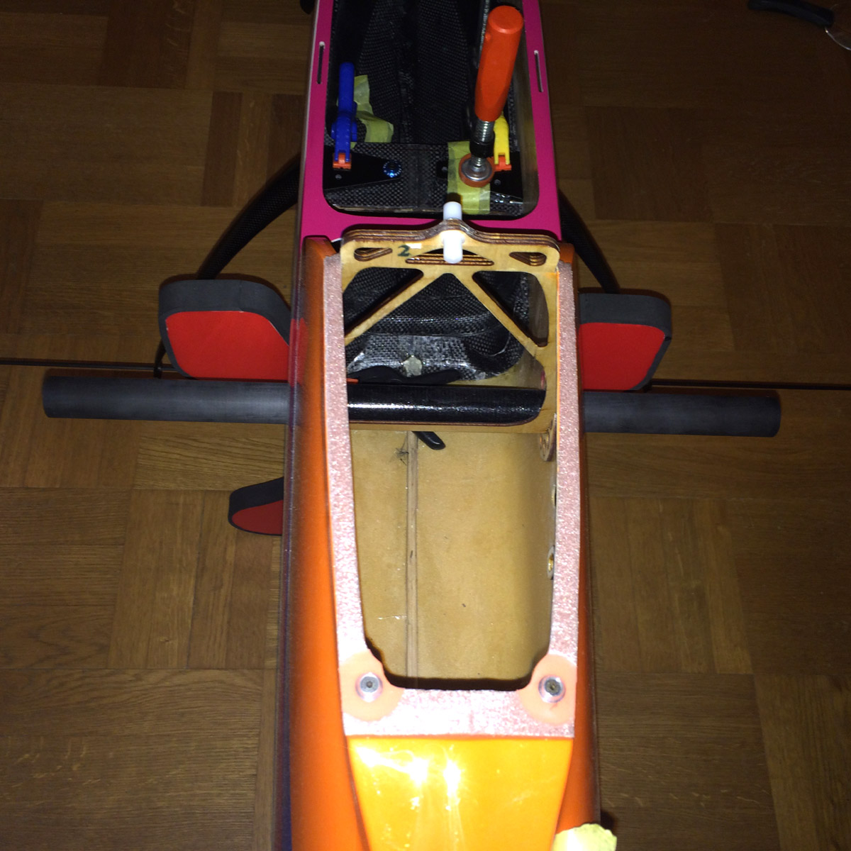
The landing gear carbon reinforced 8 mm plywood plate was recommended to be reinforced by the dealer, and when I checked underside of the mounting plate it had no support construction, not even any side supports like a triangle hardwood or similar.
So I made some side support plywood parts to lock the plate in place and prevent it to be twisted out in event very hard landing. I prefer to bend/trash the carbon landing gear instead of having the whole mounting plate be ripped out and risk of damage the fuselage sides where the legs exit fuselage side in case very hard landing.
It added maybe 10 grams with the material and glue.
I have selected to not use the wheel pants since it is rather rough grass field where I fly most. I selected larger lightweight wheels, DuBro SuperLite 70 mm (2 3/4") that weight 29.6 grams for both wheels.
Wheel axles needed was 21 mm since the 70 mm SuperLite wheels require that width, Seacraft 4 x 21 mm axles was mounted (only 6.8 grams).
The landing gear mounting including the trouble with the two screws and reinforcement
of the plate took several evenings (I had expected only one).

No reinforcement whatsoever underside of landing gear mounting plate.

I made these plywood reinforcements for the landing gear. Added about 10 grams including gluing it with slow curing epoxy.
The landing gear aligned paralell with the wing tube seen from slightly behind, using a 4 mm carbon tube through the wheel axles holes.

Landing gear legs fastened to landing gear plate with six 25 mm M4 hex steel screws with 15 mm diameter Secraft blue aluminium washers.

My Galactika on it's own feet for the first time.
Left landing gear.
Right landing gear.

Up on the bench with the newly mounted landing gear.
/Bo
At first I thought that this task would be easy and go rather quick. Oboy I was wrong.
To get the bowed (both side and front view) landing gear legs properly alligned I had to use a 4 mm carbon tube through the wheel axles so I had a reference line to get the legs and wheel axles aligned seen from above, perpendiculer to fuselage centerline.
I used the wing carbon tube and aimed to get the 4 mm carbon tube parallel to that. Using clamps to hold the landing gear against the landing gear mounting plate in fuselage (already in place from factory) I was finally satisfied and drilled the 3 holes in each gear legs mounting plate through the landing gear plywood
mounting plate. So far so good.
I had some new Secraft aluminium wood lock M4 nuts that I used on underside landing gear plate:
http://www.secraft.net/shop/step1.ph...20090803051116
This was a big misstake when using steel hex screws. When I had mounted every screws so landing gear was mounted as it should I wanted to take away the landing gear when I was working with the fuselage on a stand with other things. Then one of the screws got stuck on the thread and impossible to turn loose. Somehow I got galling despite the Secraft aluminium wood lock nut has a steel nut inside according to Secraft homepage.
I had to spend a whole evening gridning down the head of the steel hex screw with a Dremel and then I was able to bend away the wood lock nuts from underside.
I changed to steel wood luck nuts instead but then I got an unforeseen problem with one of these screws. One thread was defect and when I tighted the hex screws the thread was so weak in one of wood lock nuts that the screw just turned without possibility to fasten. I could not unscrew the screw either (that was recessed in Secraft washer).
Once again I had to use my Dremel... man, now my patience with the landing gear was almost gone.
Finally I replace the defect wood lock nut and the gear was permanetly fastened with total 6 M4 25 mm hex screws with Secraft 15 mm blue aluminium washers and my Galactika was on it's own feet for the first time.
The landing gear carbon reinforced 8 mm plywood plate was recommended to be reinforced by the dealer, and when I checked underside of the mounting plate it had no support construction, not even any side supports like a triangle hardwood or similar.
So I made some side support plywood parts to lock the plate in place and prevent it to be twisted out in event very hard landing. I prefer to bend/trash the carbon landing gear instead of having the whole mounting plate be ripped out and risk of damage the fuselage sides where the legs exit fuselage side in case very hard landing.
It added maybe 10 grams with the material and glue.
I have selected to not use the wheel pants since it is rather rough grass field where I fly most. I selected larger lightweight wheels, DuBro SuperLite 70 mm (2 3/4") that weight 29.6 grams for both wheels.
Wheel axles needed was 21 mm since the 70 mm SuperLite wheels require that width, Seacraft 4 x 21 mm axles was mounted (only 6.8 grams).
The landing gear mounting including the trouble with the two screws and reinforcement
of the plate took several evenings (I had expected only one).
No reinforcement whatsoever underside of landing gear mounting plate.
I made these plywood reinforcements for the landing gear. Added about 10 grams including gluing it with slow curing epoxy.
The landing gear aligned paralell with the wing tube seen from slightly behind, using a 4 mm carbon tube through the wheel axles holes.
Landing gear legs fastened to landing gear plate with six 25 mm M4 hex steel screws with 15 mm diameter Secraft blue aluminium washers.
My Galactika on it's own feet for the first time.
Left landing gear.
Right landing gear.
Up on the bench with the newly mounted landing gear.
/Bo
Last edited by bem; 05-02-2016 at 03:21 PM.
04-30-2016, 04:20 PM
#11

My Feedback: (53)

So,your running 5v on HV servos? You could save some weight by going 8v on the ESC using the Jeti dual switch 10gr and connect the backup battery...on side B, it will go between each input using the highest one so you will be on 2s battery for a short time then remain on ESC the rest of the day....much lighter and smaller...
04-30-2016, 04:56 PM
#12
Hi,
Yes all Futaba servos I use in my Galactika is High Voltage (HV), and I have BEC voltage in Master Mezon set to 7.4 volt.
OK, 10 grams for Jeti dual switch. Then I need a 2 cell LiPo also - they may weight for example 18 grams for an Gensace 200 mAh or 10 grams for 160 mAh. Total 28 or 20 grams. Compared to Scorpion Backup Guard 37 grams. 9 or 17 grams savings.
Do You have any link to this Jeti 10 gram dual switch?
/Bo
Yes all Futaba servos I use in my Galactika is High Voltage (HV), and I have BEC voltage in Master Mezon set to 7.4 volt.
You could save some weight by going 8v on the ESC using the Jeti dual switch 10gr and connect the backup battery...on side B, it will go between each input using the highest one so you will be on 2s battery for a short time then remain on ESC the rest of the day....much lighter and smaller...
Do You have any link to this Jeti 10 gram dual switch?
/Bo
04-30-2016, 05:24 PM
#13
My Feedback: (53)
Here's the link...this is a slick unit...I switch all my switch to these..
http://www.espritmodel.com/jeti-elec...y-dsm-esc.aspx
its also about the size...so small and light that I just used a tiny piece of Velcro on each side to hold it in place....
http://www.espritmodel.com/jeti-elec...y-dsm-esc.aspx
its also about the size...so small and light that I just used a tiny piece of Velcro on each side to hold it in place....
04-30-2016, 05:54 PM
#14
c) Mounting servos, linkages and the stab.
I decided to use the Futaba S.BUS2 Brushless servos (Made in Tawain by the way) that is recommended for Galactika, although all the recommended servos cost a fortune.
Elevator:
BLS173SV x 2 ("mini" servo)
Weight 28 gram (0.99 oz) - total weight for both 56 grams (1.975 oz)
6.0 - 7.4 volt
Speed 0.11 sec/60 deg at 6.6 volt, 0.10 at 7.4 volt
Torque 6.8 kgf * cm at 6.6 volt, 7.6 kgf * cm at 7.4 volt
Seize 33x15x27.1 mm (1.30x0.59x1.07 in)
Aileron:
BLS174SV x 2 ("low profile" servo with 6 degree slope on top deck)
Weight 53 gram (1.87 oz) - total weight for both 106 grams (3.739 oz)
6.0 - 7.4 volt
Speed 0.10 sec/60 deg at 6.6 volt, 0.09 at 7.4 volt
Torque 8.8 kgf * cm at 6.6 volt, 9.6 kgf * cm at 7.4 volt
Seize 47.5x27x25.4 mm (1.87x1.06x1.0 in)
Rudder:
BLS171SV x 2 ("standard" servo seize/weight)
Weight 48 gram (1.69 oz)
6.0 - 7.4 volt
Speed 0.11 sec/60 deg at 6.6 volt, 0.10 at 7.4 volt
Torque 10.6 kgf * cm at 6.6 volt, 11.8 kgf * cm at 7.4 volt
Seize 47.5x27x25.4 mm (1.87x1.06x1.0 in)
Mounting elevator servos:
To drop in the BLS173SV elevator servos in the stabs the plywood mounting plate hole had to be slightly carved out to get it slightly longer. The servos was mounted with both the rubber grommets and the metal insert in the grommet and fastened with 2.2 x 11 mm hex servoscrews. I brushed a layer of epoxy top and underside on the plywood mounting to get little tighter fit for the screws and prevent breakup of plywood when the screws was tightened.
Servo arm I selected to use is the same as I use in my Sebart MythoS Pro, it is 15 mm metal servo arm from Robbe (item no 8512, discontinued). Ball bearing link is attached to the servo arm at second hole that is 8.5 mm out from center servo screw.
Elevator horn (metal), links (plastic with ball bearing in one end) and metal rod (with threads so one can twist the rod to adjust the length) was supplied as Oxai accessories and fitted nicely.
The main work was to cut out the holes on underside stabs where the rod goes through to the horns. Also the plastic cover over that hole was quite some work to cut out, trim and sand to perfect fit and last glue with thin CA.
Last I added a label on each stab at the plastic cover with the servo ID and Channel used and that way it is easier if the servo (althoug unlikely) needs to be adjusted later with Futaba S. Link PC Programmer application. I did this labeling at all servos in the plane.
The elevator servos is connected to a 4 socket S.BUS hub in the tail, and I use fixed connectors glued on side of fuselage to quick and easy connect the elevator servos if stabs are removed/attached at transportation. It is Robbe fixed connector (item no F1639, discontinued) I use.
The servo connectors in the S.BUS hub is secured with dental floss.
This is a good thing to save some weight in general and specifically in tail.
Although I have not done it yet, one can shorten the servo cables as much as possible to save some more weight.
Elevator, rudder and fixed connector leads can be shortened considerably if one want.
Throwns on elevator was intitially set for normal flying to 8.0 degrees up and 8.5 down, and max allowable throws is around 17 degrees, I set max up to 17.0 and max down to 17.5 degrees.
The elevators are pre hinged from factory with minimal gap (about 0.1 mm) so this was nicely done at factory.
Stabs was an easy install, two carbon tubes go through fuselage and in each carbon tube ends it is hardwood pieces so M2.5 hex screws is going through that and hold the stab in place. All fitted perfectly from factory.
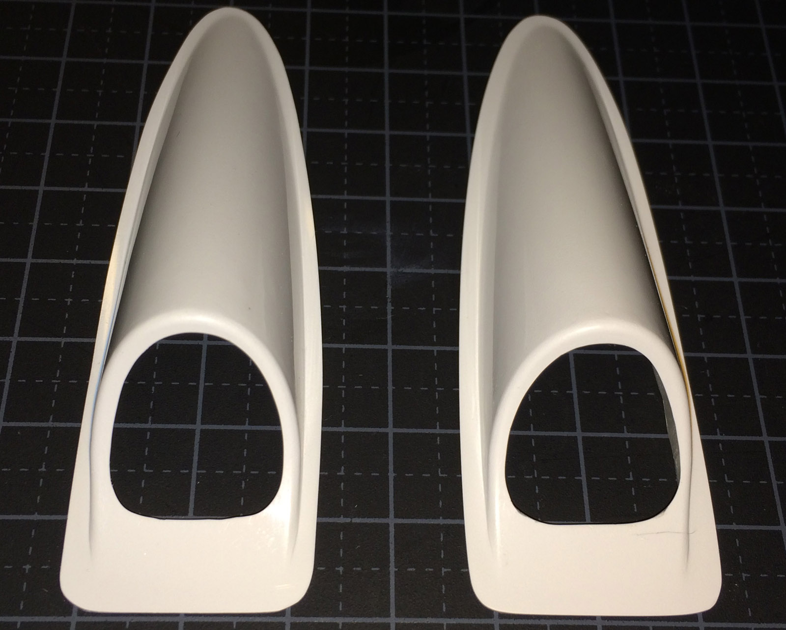
The white plastic covers over the hole for the elevator rods was more work with then expected.
First I had to trim the outer edges leaving about 2 mm edge and then open the hole for the rod to go through to the elevator horn. That was a slow job since the plastic seemed to be rather fragile and I wanted no cracks. Finally it was finished and they where glued to the stabs with thin CA letting the capillary force do the job.
This work took much longer then expected.
In the tail it is also a hole in front of tail wheel for adjusting the stab incidence with a 120 mm or longer 2.5 mm hex wrench. Whole stab is adjusted as one unit so You can not adjust incidence on each stab individually.
Mounting aileron servos:
The BLS174SV aileron servos did fit without carving in the wing but needed slightly rased mounting plate to get perfectly aligned with wing skin. 0,5 mm plywood spacer was glued and then the servo was aligned with the surface. 2.2 x 11 mm hex servo screws was used also here.
Servo lead length has enough length and about 150 mm (5.9 in) remained outside wing root to connect to fuselage fixed connector (same Robbe fixed connector and lead type as used for elevator guick connector).
Servo arm I use is the plastic arm that was shipped with the BLS174SV servo, and I cut away plastic material on the servo arm that was not needed. The servo arm mounting shaft is wider then on mini and standard servos so the metal arm I planned to use did not fit, wrong spline. It had to be the plastic arm that came with the servo. It is "F4" spline 25 tooth on this servo.
The ballbearing link is mounted 17 mm out in 3rd hole on servo arm and this gives max physical allowed throws on aileron.
Throws I set initially was 8.0 degrees up/down and max was 17.0 degrees up/down.
The metal aileron horns supplied by Oxai was screwed to aileron with 2.2 x 8 mm hex servoscrews, the aileron had already plywood under the aileron skin for the screws fastening.
Aileron horn height up to the ball link mounting hole is 27 mm.
Ailerons are pre hinged from factory with minimal gap (about 0.1-0.2 mm) so this was nicely done at factory.
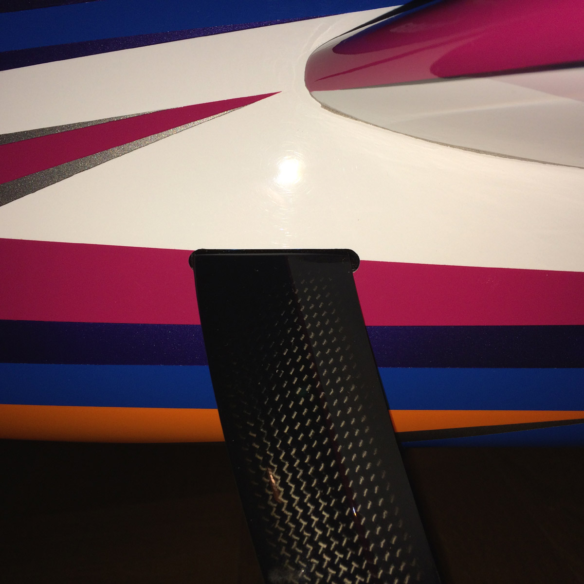
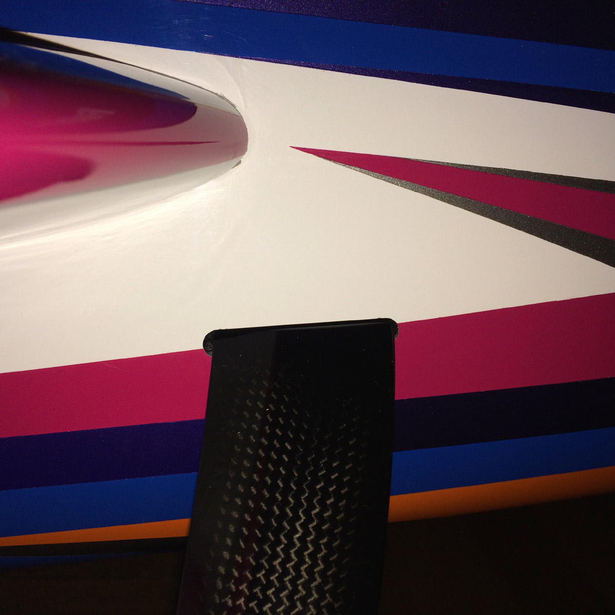
Mounting rudder servo:
The BLS171SV ruder servo fitted directly in the tail plywood mounting plate supplied by Oxai.
The plate is glued in the tail underside opening where it is a hatch for rudder servo.
Oxai supply in the accessories bag also a long carbon servo arm predrilled that is screwed to the standard round servo arm that ships with BLS171SV that gives proper throws.
Ball bearing links and carbon rod (that is glued to metal threaded ends) is also supplied and all fit nicely.
It is rather crowded under the hatch where the rudder servo is mounted when all is in place (carbon servo arm, rods, S.BUS hub where 4 servo connectors meet - one that comes from front S.BUS hub, two for the elevator servos and one for rudder).
Throws on rudder has been set for normal flying to 16.5 degrees and for high rate (spin / stall turn / snap) to 36.0 degrees.
The tail hatch is a little tricky to mount and unmount but with some coaxing it works.
The hatch is fastened with a 2.2 x 11 mm hex servo screw and in front it is held in place by a flange and I mounted some Secraft padding material there to prevent rattle.
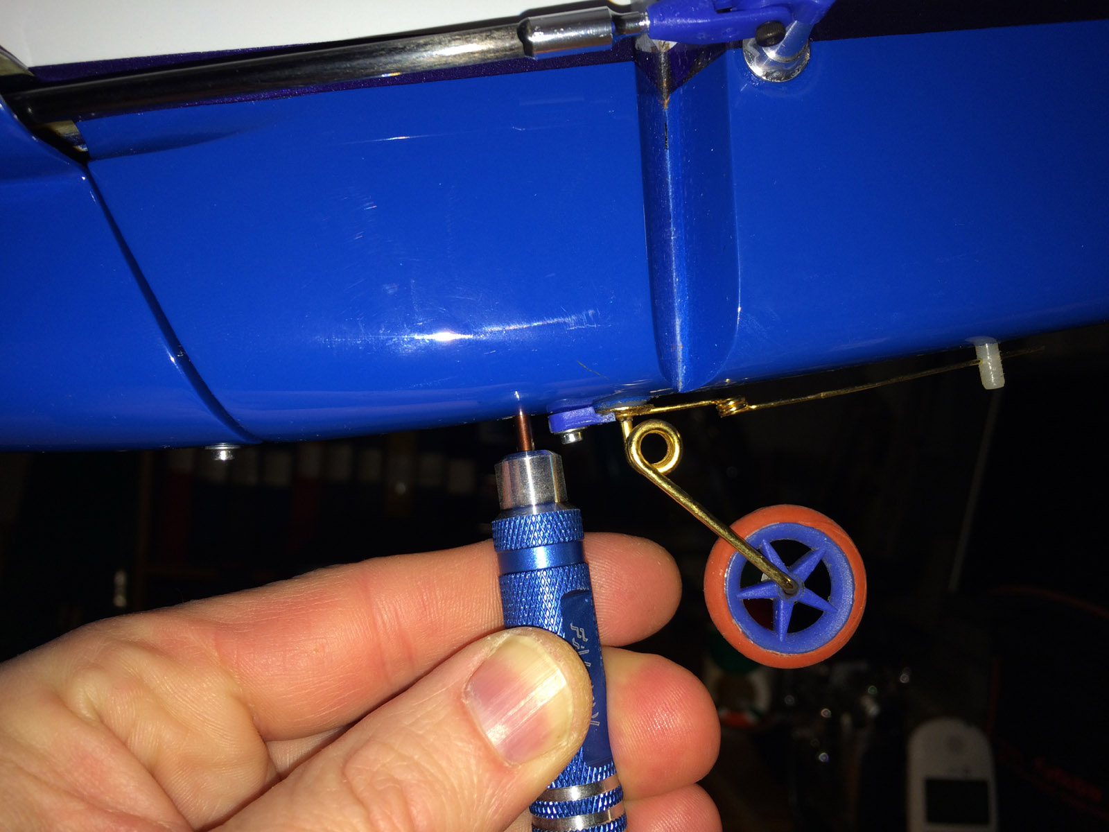
When all this was done the tailwheel was mounted using all parts supplied by Oaxi.
The tail wheel wire and mounting is OK and seems to be able to cope with also little harder encounter with the ground. There is a thinner pianowire extending to rear that is fastened in a nylon rod in rudder that follow rudder movements making stearing of tailwheel work nicely.
The tailwheel itself is very narrow and the rubber on the rim is thin and on one landing I saw the tyre fly off the rim, and I had to glue the tyre to rim with CA to be sure it stay in place.
The work mounting the elevators, ailerons and rudder servos, glueing the mounting plate etc and mounting the tail wheel etc took 4 evenings for me, more time then I expected (as usual).
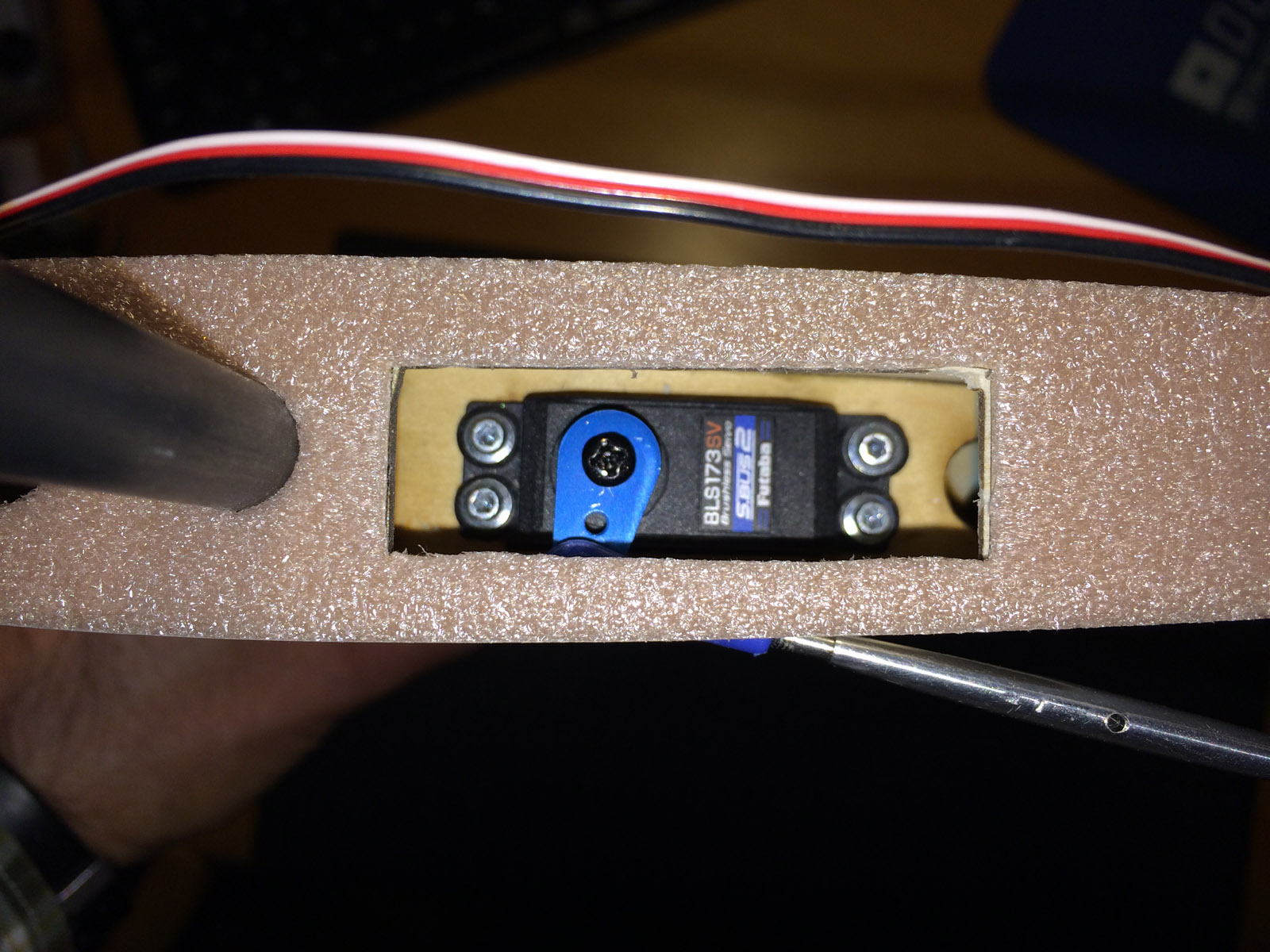
One elevator servo mounted. 2 mm soft material is mounted from factory on stab root to get a tight and soft contact with fuselage side when stab is mounted.


Slots for elevator rods had to be cut out. One stab ready, carbon tubes has been mounted and the two mounting screws has been tightened.
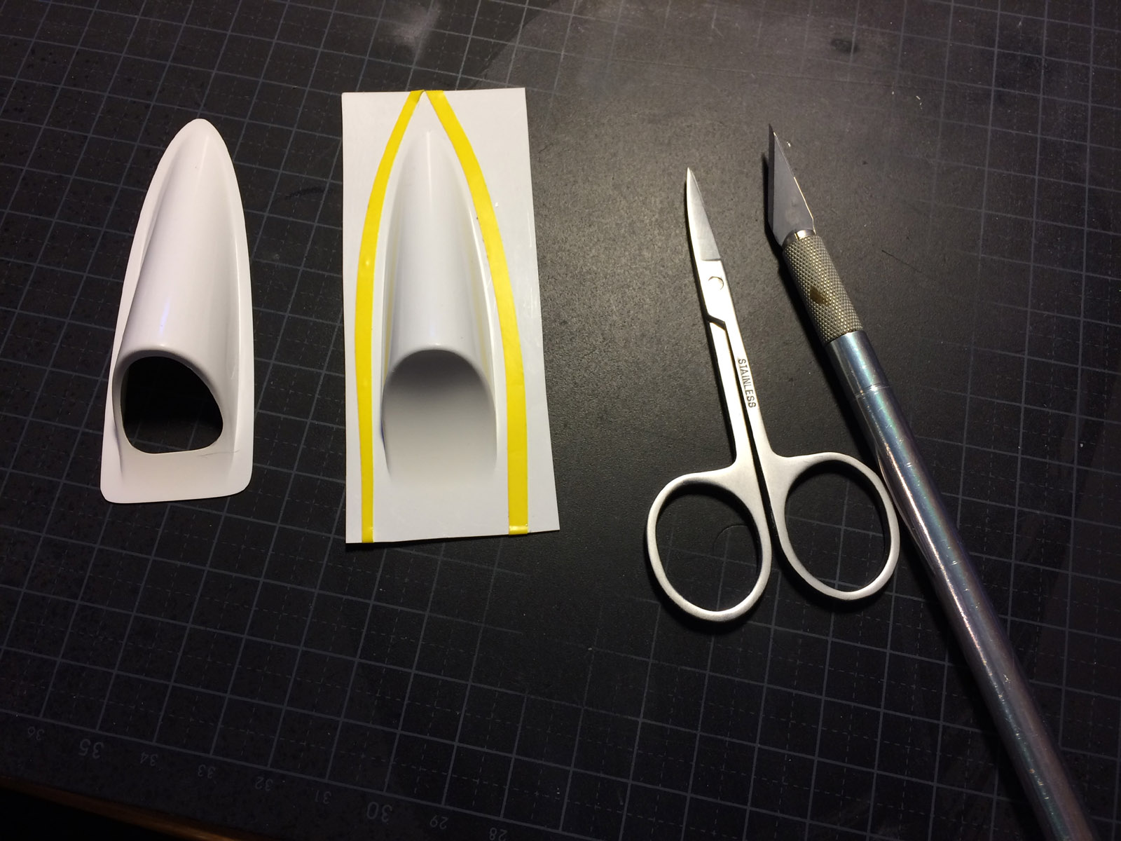

The white plastic covers had to be trimmed and mounted over the holes in the stabs.
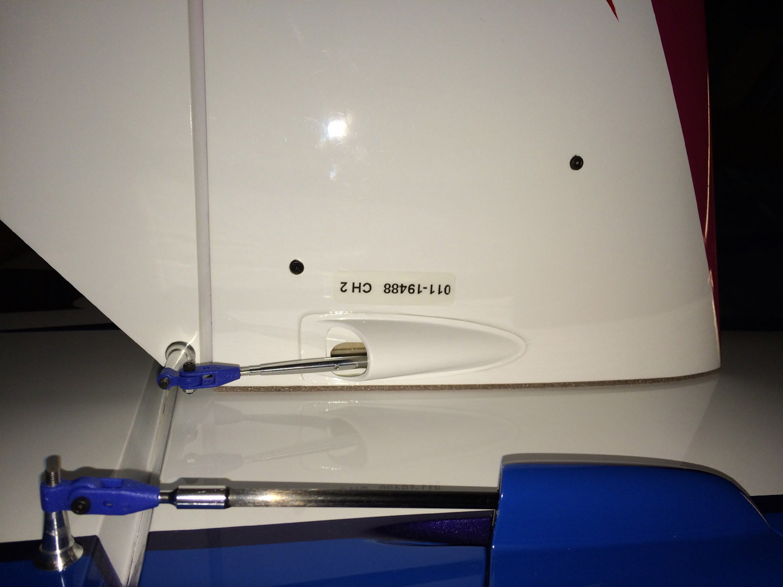
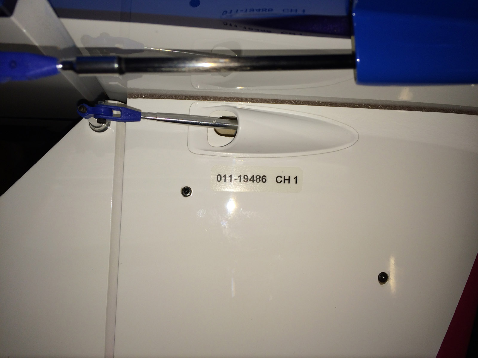
The cover has been glued to the stabs. Notice the labels with S.BUS servo ID number.


Stabs is easily unmounted/mounted. Quick fixed servo connector is mounted in fuselage.


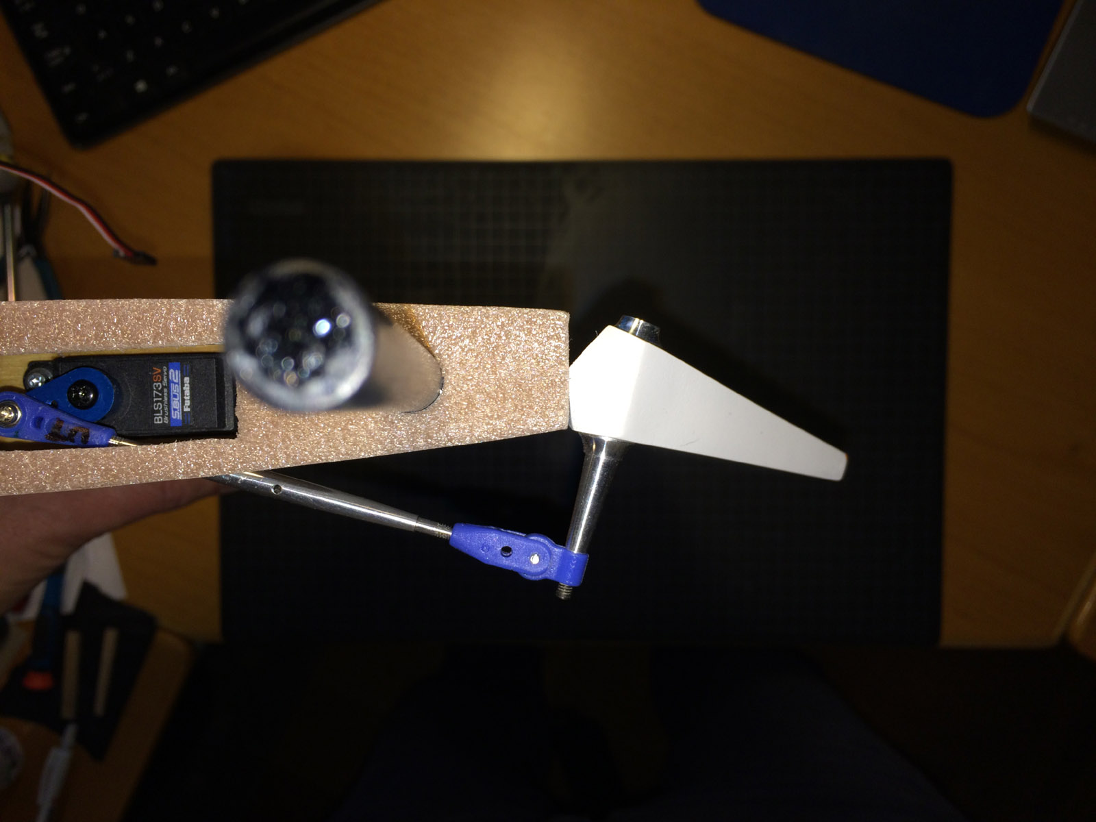
Servo max physical throws that is possible (about 17-18 degrees up/down).

S.BUS 4 way connector in tail and the single servo lead to the tail (trough a paper made tunnel). Adjustment screw for stab incidence adjustment in the tail.
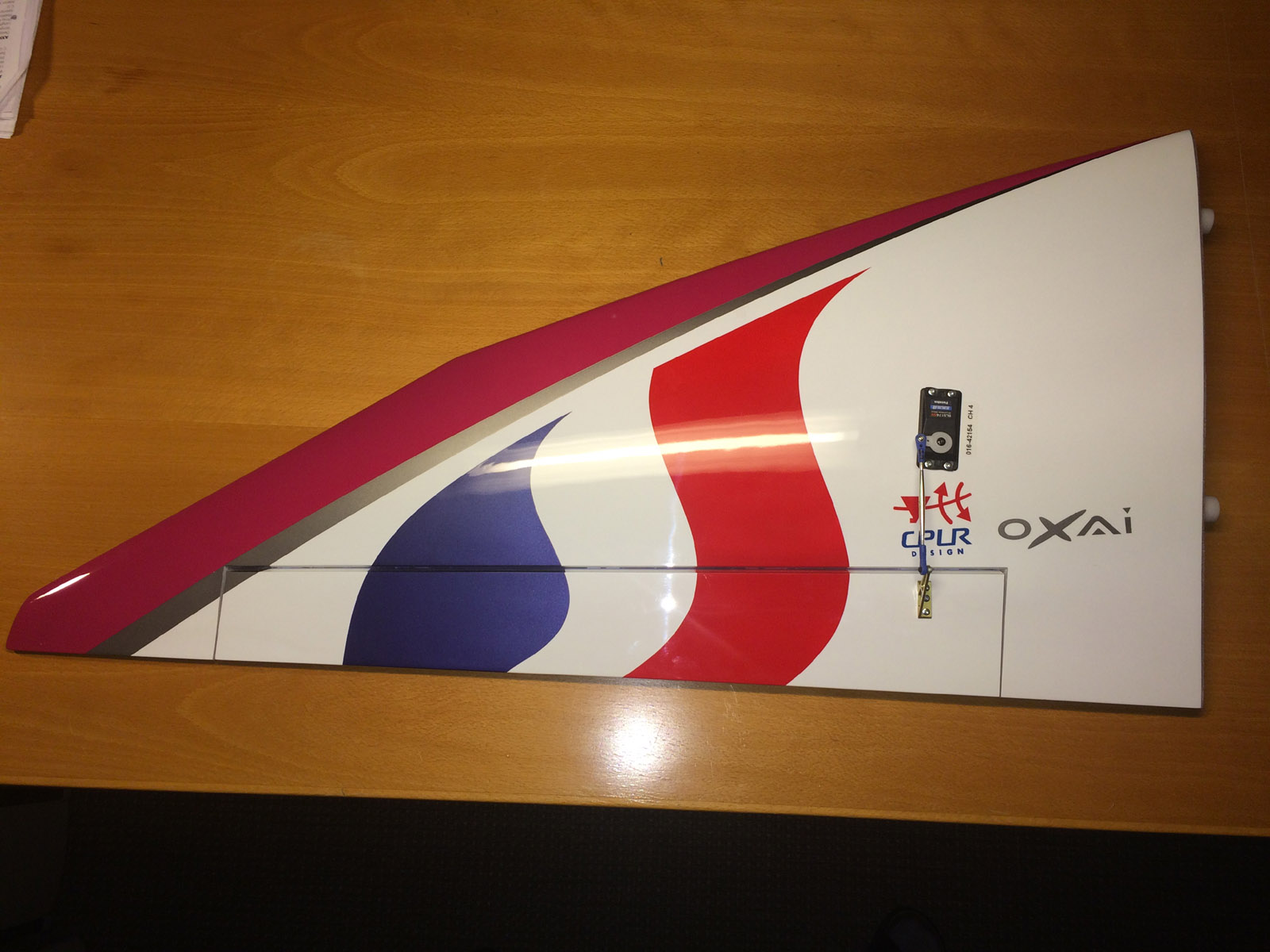


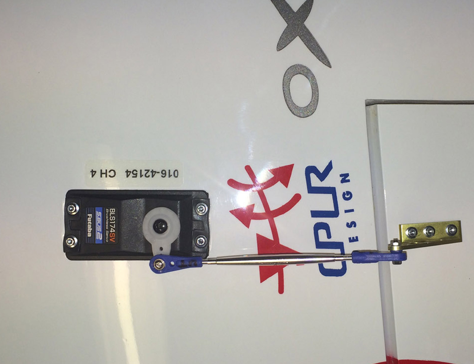
Servos mounted in the wings.

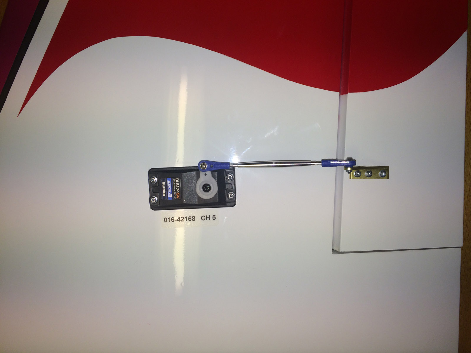

Aileron servo linkages. Wing servo connector in fuselage for Quick mounting and unmounting of the wings.

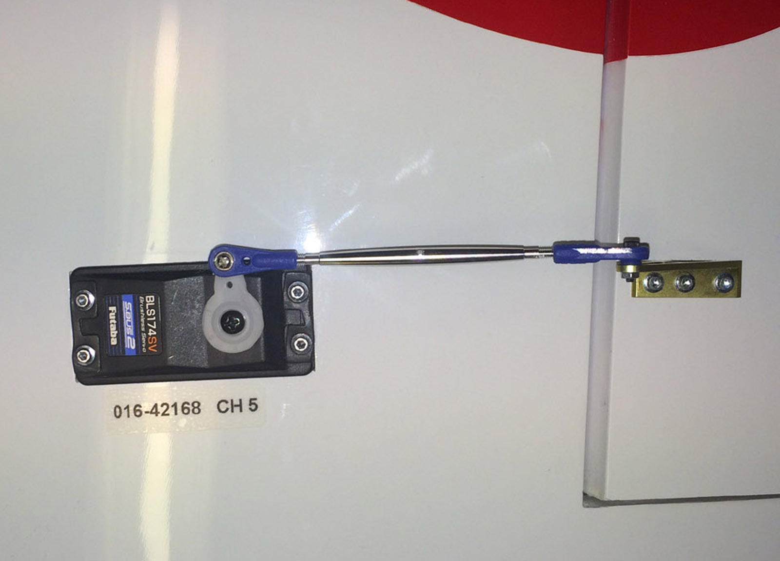
Max physical throws on ailerons (about 17-18 degrees up/down).


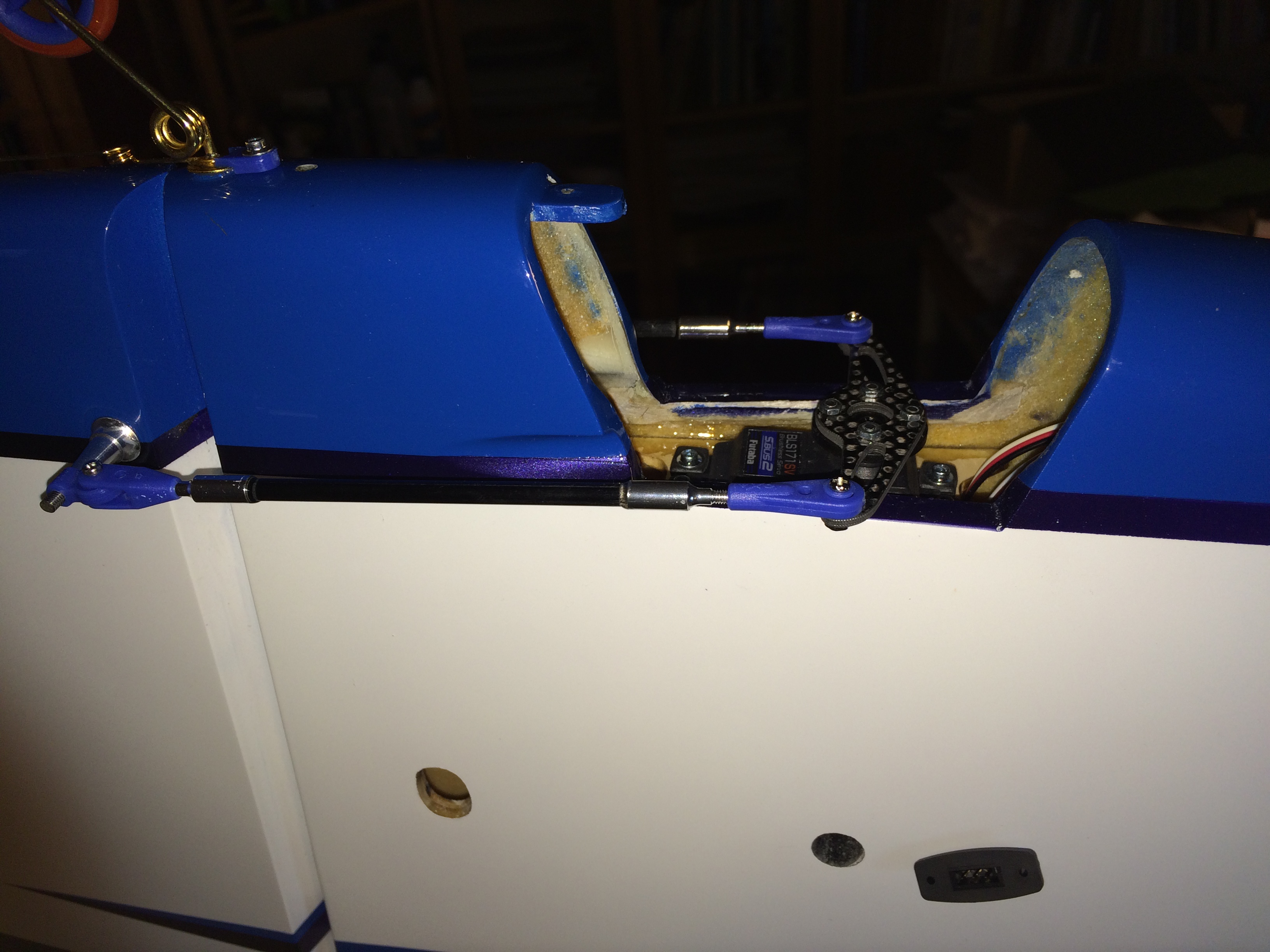
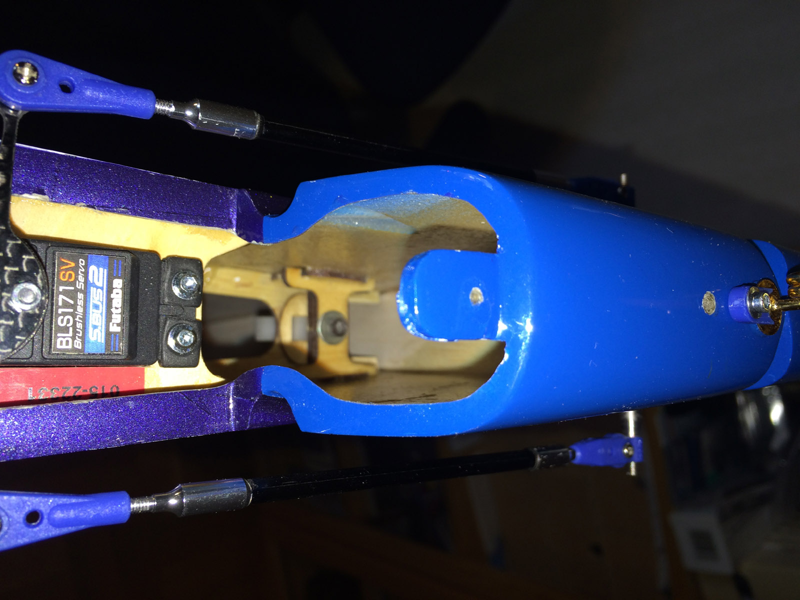
Rudder servo mounted and linkages attached.


Tailwheel mounted. Hatch mounted over the compartment for rudder servo and S.BUS hub.

Max physical throws on rudder.
/Bo
I decided to use the Futaba S.BUS2 Brushless servos (Made in Tawain by the way) that is recommended for Galactika, although all the recommended servos cost a fortune.
Elevator:
BLS173SV x 2 ("mini" servo)
Weight 28 gram (0.99 oz) - total weight for both 56 grams (1.975 oz)
6.0 - 7.4 volt
Speed 0.11 sec/60 deg at 6.6 volt, 0.10 at 7.4 volt
Torque 6.8 kgf * cm at 6.6 volt, 7.6 kgf * cm at 7.4 volt
Seize 33x15x27.1 mm (1.30x0.59x1.07 in)
Aileron:
BLS174SV x 2 ("low profile" servo with 6 degree slope on top deck)
Weight 53 gram (1.87 oz) - total weight for both 106 grams (3.739 oz)
6.0 - 7.4 volt
Speed 0.10 sec/60 deg at 6.6 volt, 0.09 at 7.4 volt
Torque 8.8 kgf * cm at 6.6 volt, 9.6 kgf * cm at 7.4 volt
Seize 47.5x27x25.4 mm (1.87x1.06x1.0 in)
Rudder:
BLS171SV x 2 ("standard" servo seize/weight)
Weight 48 gram (1.69 oz)
6.0 - 7.4 volt
Speed 0.11 sec/60 deg at 6.6 volt, 0.10 at 7.4 volt
Torque 10.6 kgf * cm at 6.6 volt, 11.8 kgf * cm at 7.4 volt
Seize 47.5x27x25.4 mm (1.87x1.06x1.0 in)
Mounting elevator servos:
To drop in the BLS173SV elevator servos in the stabs the plywood mounting plate hole had to be slightly carved out to get it slightly longer. The servos was mounted with both the rubber grommets and the metal insert in the grommet and fastened with 2.2 x 11 mm hex servoscrews. I brushed a layer of epoxy top and underside on the plywood mounting to get little tighter fit for the screws and prevent breakup of plywood when the screws was tightened.
Servo arm I selected to use is the same as I use in my Sebart MythoS Pro, it is 15 mm metal servo arm from Robbe (item no 8512, discontinued). Ball bearing link is attached to the servo arm at second hole that is 8.5 mm out from center servo screw.
Elevator horn (metal), links (plastic with ball bearing in one end) and metal rod (with threads so one can twist the rod to adjust the length) was supplied as Oxai accessories and fitted nicely.
The main work was to cut out the holes on underside stabs where the rod goes through to the horns. Also the plastic cover over that hole was quite some work to cut out, trim and sand to perfect fit and last glue with thin CA.
Last I added a label on each stab at the plastic cover with the servo ID and Channel used and that way it is easier if the servo (althoug unlikely) needs to be adjusted later with Futaba S. Link PC Programmer application. I did this labeling at all servos in the plane.
The elevator servos is connected to a 4 socket S.BUS hub in the tail, and I use fixed connectors glued on side of fuselage to quick and easy connect the elevator servos if stabs are removed/attached at transportation. It is Robbe fixed connector (item no F1639, discontinued) I use.
The servo connectors in the S.BUS hub is secured with dental floss.
This is a good thing to save some weight in general and specifically in tail.
Although I have not done it yet, one can shorten the servo cables as much as possible to save some more weight.
Elevator, rudder and fixed connector leads can be shortened considerably if one want.
Throwns on elevator was intitially set for normal flying to 8.0 degrees up and 8.5 down, and max allowable throws is around 17 degrees, I set max up to 17.0 and max down to 17.5 degrees.
The elevators are pre hinged from factory with minimal gap (about 0.1 mm) so this was nicely done at factory.
Stabs was an easy install, two carbon tubes go through fuselage and in each carbon tube ends it is hardwood pieces so M2.5 hex screws is going through that and hold the stab in place. All fitted perfectly from factory.
The white plastic covers over the hole for the elevator rods was more work with then expected.
First I had to trim the outer edges leaving about 2 mm edge and then open the hole for the rod to go through to the elevator horn. That was a slow job since the plastic seemed to be rather fragile and I wanted no cracks. Finally it was finished and they where glued to the stabs with thin CA letting the capillary force do the job.
This work took much longer then expected.
In the tail it is also a hole in front of tail wheel for adjusting the stab incidence with a 120 mm or longer 2.5 mm hex wrench. Whole stab is adjusted as one unit so You can not adjust incidence on each stab individually.
Mounting aileron servos:
The BLS174SV aileron servos did fit without carving in the wing but needed slightly rased mounting plate to get perfectly aligned with wing skin. 0,5 mm plywood spacer was glued and then the servo was aligned with the surface. 2.2 x 11 mm hex servo screws was used also here.
Servo lead length has enough length and about 150 mm (5.9 in) remained outside wing root to connect to fuselage fixed connector (same Robbe fixed connector and lead type as used for elevator guick connector).
Servo arm I use is the plastic arm that was shipped with the BLS174SV servo, and I cut away plastic material on the servo arm that was not needed. The servo arm mounting shaft is wider then on mini and standard servos so the metal arm I planned to use did not fit, wrong spline. It had to be the plastic arm that came with the servo. It is "F4" spline 25 tooth on this servo.
The ballbearing link is mounted 17 mm out in 3rd hole on servo arm and this gives max physical allowed throws on aileron.
Throws I set initially was 8.0 degrees up/down and max was 17.0 degrees up/down.
The metal aileron horns supplied by Oxai was screwed to aileron with 2.2 x 8 mm hex servoscrews, the aileron had already plywood under the aileron skin for the screws fastening.
Aileron horn height up to the ball link mounting hole is 27 mm.
Ailerons are pre hinged from factory with minimal gap (about 0.1-0.2 mm) so this was nicely done at factory.
Mounting rudder servo:
The BLS171SV ruder servo fitted directly in the tail plywood mounting plate supplied by Oxai.
The plate is glued in the tail underside opening where it is a hatch for rudder servo.
Oxai supply in the accessories bag also a long carbon servo arm predrilled that is screwed to the standard round servo arm that ships with BLS171SV that gives proper throws.
Ball bearing links and carbon rod (that is glued to metal threaded ends) is also supplied and all fit nicely.
It is rather crowded under the hatch where the rudder servo is mounted when all is in place (carbon servo arm, rods, S.BUS hub where 4 servo connectors meet - one that comes from front S.BUS hub, two for the elevator servos and one for rudder).
Throws on rudder has been set for normal flying to 16.5 degrees and for high rate (spin / stall turn / snap) to 36.0 degrees.
The tail hatch is a little tricky to mount and unmount but with some coaxing it works.
The hatch is fastened with a 2.2 x 11 mm hex servo screw and in front it is held in place by a flange and I mounted some Secraft padding material there to prevent rattle.
When all this was done the tailwheel was mounted using all parts supplied by Oaxi.
The tail wheel wire and mounting is OK and seems to be able to cope with also little harder encounter with the ground. There is a thinner pianowire extending to rear that is fastened in a nylon rod in rudder that follow rudder movements making stearing of tailwheel work nicely.
The tailwheel itself is very narrow and the rubber on the rim is thin and on one landing I saw the tyre fly off the rim, and I had to glue the tyre to rim with CA to be sure it stay in place.
The work mounting the elevators, ailerons and rudder servos, glueing the mounting plate etc and mounting the tail wheel etc took 4 evenings for me, more time then I expected (as usual).
One elevator servo mounted. 2 mm soft material is mounted from factory on stab root to get a tight and soft contact with fuselage side when stab is mounted.
Slots for elevator rods had to be cut out. One stab ready, carbon tubes has been mounted and the two mounting screws has been tightened.
The white plastic covers had to be trimmed and mounted over the holes in the stabs.
The cover has been glued to the stabs. Notice the labels with S.BUS servo ID number.
Stabs is easily unmounted/mounted. Quick fixed servo connector is mounted in fuselage.
Servo max physical throws that is possible (about 17-18 degrees up/down).
S.BUS 4 way connector in tail and the single servo lead to the tail (trough a paper made tunnel). Adjustment screw for stab incidence adjustment in the tail.
Servos mounted in the wings.
Aileron servo linkages. Wing servo connector in fuselage for Quick mounting and unmounting of the wings.
Max physical throws on ailerons (about 17-18 degrees up/down).
Rudder servo mounted and linkages attached.
Tailwheel mounted. Hatch mounted over the compartment for rudder servo and S.BUS hub.
Max physical throws on rudder.
/Bo
Last edited by bem; 05-10-2016 at 11:21 PM.
04-30-2016, 06:14 PM
#15
Here's the link...this is a slick unit...I switch all my switch to these..
http://www.espritmodel.com/jeti-elec...y-dsm-esc.aspx
its also about the size...so small and light that I just used a tiny piece of Velcro on each side to hold it in place....
http://www.espritmodel.com/jeti-elec...y-dsm-esc.aspx
its also about the size...so small and light that I just used a tiny piece of Velcro on each side to hold it in place....
Thanks for the link. It say that weight is 24 grams, not 10 grams. Or is it wrong weight written on that page?
/Bo
05-01-2016, 05:16 AM
#16
Hi,
I found this photo in my iPhone today from the assembly earlier in April. What a mess on the table...

The strange thing is that I somehow manage to keep track of where all things are in this mess. I suppose it is a sixth sense, the brain know I need to know where all things are so it keep track of it for me. On a few occasion I could not find some things on the table but then I usually found it in the trash can under the table
The next photo below is taken efter I finished assembly of my Galactika - and the table still remain clean today. I do not plan any build or assembly for a while now on this table - fine trimming and flying my Galactika as much as I have time is now nr 1 priority.

/Bo
I found this photo in my iPhone today from the assembly earlier in April. What a mess on the table...
The strange thing is that I somehow manage to keep track of where all things are in this mess. I suppose it is a sixth sense, the brain know I need to know where all things are so it keep track of it for me. On a few occasion I could not find some things on the table but then I usually found it in the trash can under the table
The next photo below is taken efter I finished assembly of my Galactika - and the table still remain clean today. I do not plan any build or assembly for a while now on this table - fine trimming and flying my Galactika as much as I have time is now nr 1 priority.
/Bo
Last edited by bem; 05-01-2016 at 09:03 AM.
05-01-2016, 07:58 AM
#17
d) Mounting S.BUS hubs, one in tail and one under wing tube on fuselage floor.
On my Galactika I decided to go all S.BUS2.
Two S.BUS hubs was needed to solve this, one in the tail and one in fuselage on floor under the wing carbon tube.
In tail I use Futaba S.Bus Terminal Box 4-Way and in fuselage Futaba S.Bus Terminal Box 6-Way.
In tail I mounted the 4-way hub on a Herex laminated carbon plate that was glued in front of the hatch opening. In fuselage I mounted the 6-way hub on a Herex laminated carbon plate also.
It is pros and cons with the S.BUS and the wiring.
Pros are for example less servo cables to reduce weight, You can supply power anywhere in the S.BUS chain and You can program each S.BUS servo with Futaba S. Link PC Programmer application.
One of the cons is the redundancy since for example in my case the single servo lead to tail hub is only one, and from receiver S.BUS2 connector to hub it is only one servo lead also.
There is also the servo ID number to remember when selecting channel for the S.BUS servos to fit channel assignment in transmitter. I taped small lables near each servos with their S.BUS servo ID number to help me remember this.
Although it was some reading needed to understand S.BUS I think I have now a resonable good understanding of it and feel comfortable with it. I hope I will not regret switching over to S.BUS2 only in my Galactika.
Another downside when using S.BUS2 with my receiver R6308SBT is that it can not be set in High speed mode when S.BUS2 sensors are used (that I use, the current sensor).
I suppose S.BUS/S.BUS2 is what I will continue to use in any future F3A plane I will assemble, at least to I'm proven it is some cons with it that I have not discovered yet that would make me decide not using it.

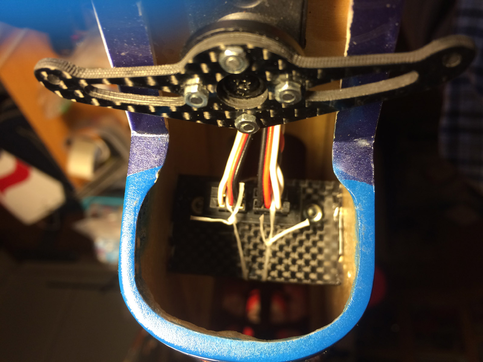
Futaba 6-way S.BUS hub in front of fuselage below wing tube.

Aileron servos connection to the S.BUS hub.

Futaba 4-way S.BUS hub in tail. All 4 connectors filled: 1) From S.BUS hub in front of fuselage, 2) Right elevator servo, 3) Left elevator servo and 4) Rudder servo.

The servo connectors are secured to the S.BUS hub connectors with dental floss.


S.BUS servo ID numbers on lables at each servos so it can be seen clearly. The ID number is needed if one want to change settings with Futaba S.Link PC Programmer application.
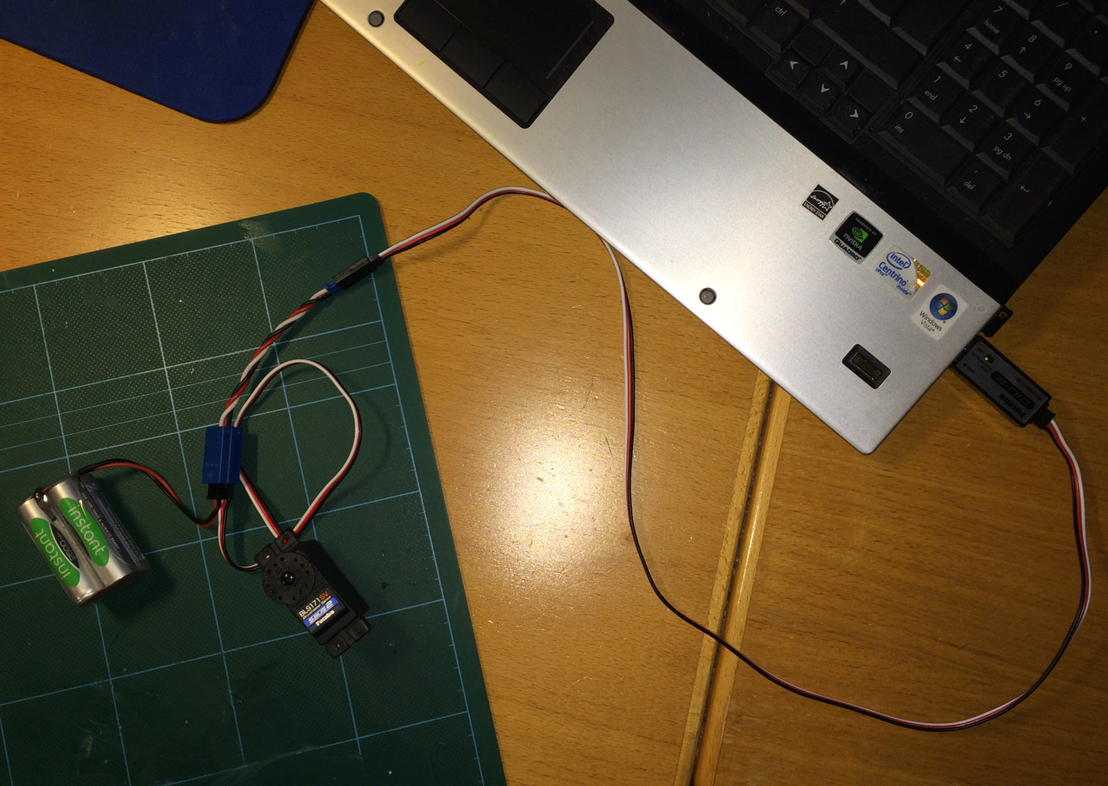
One S.BUS2 servo connected to Futaba CIU-2 USB interface that is needed to communicate with Futaba S.Link PC Programmer application on a PC and S.BUS servos. If one have a Futaba transmitter that support programming of S.BUS servos directly from transmitter, like 18SZ or 18MZ, You can program S.BUS servos directly that way instead if You prefer.

Futaba S.Link PC Programmer application where You can change many settings on a S.BUS/S.BUS2 servo, for exampe assign Channel, Soft start of servco (when power is applied), Reverse, Dead band and much more.
Here is little more valuable info on what to consider when using S.BUS servos in pattern planes:
http://www.ckaero.net/blog/2016/04/0...orth-the-fuss/
/Bo
On my Galactika I decided to go all S.BUS2.
Two S.BUS hubs was needed to solve this, one in the tail and one in fuselage on floor under the wing carbon tube.
In tail I use Futaba S.Bus Terminal Box 4-Way and in fuselage Futaba S.Bus Terminal Box 6-Way.
In tail I mounted the 4-way hub on a Herex laminated carbon plate that was glued in front of the hatch opening. In fuselage I mounted the 6-way hub on a Herex laminated carbon plate also.
It is pros and cons with the S.BUS and the wiring.
Pros are for example less servo cables to reduce weight, You can supply power anywhere in the S.BUS chain and You can program each S.BUS servo with Futaba S. Link PC Programmer application.
One of the cons is the redundancy since for example in my case the single servo lead to tail hub is only one, and from receiver S.BUS2 connector to hub it is only one servo lead also.
There is also the servo ID number to remember when selecting channel for the S.BUS servos to fit channel assignment in transmitter. I taped small lables near each servos with their S.BUS servo ID number to help me remember this.
Although it was some reading needed to understand S.BUS I think I have now a resonable good understanding of it and feel comfortable with it. I hope I will not regret switching over to S.BUS2 only in my Galactika.
Another downside when using S.BUS2 with my receiver R6308SBT is that it can not be set in High speed mode when S.BUS2 sensors are used (that I use, the current sensor).
I suppose S.BUS/S.BUS2 is what I will continue to use in any future F3A plane I will assemble, at least to I'm proven it is some cons with it that I have not discovered yet that would make me decide not using it.
Futaba 6-way S.BUS hub in front of fuselage below wing tube.
Aileron servos connection to the S.BUS hub.
Futaba 4-way S.BUS hub in tail. All 4 connectors filled: 1) From S.BUS hub in front of fuselage, 2) Right elevator servo, 3) Left elevator servo and 4) Rudder servo.
The servo connectors are secured to the S.BUS hub connectors with dental floss.
S.BUS servo ID numbers on lables at each servos so it can be seen clearly. The ID number is needed if one want to change settings with Futaba S.Link PC Programmer application.
One S.BUS2 servo connected to Futaba CIU-2 USB interface that is needed to communicate with Futaba S.Link PC Programmer application on a PC and S.BUS servos. If one have a Futaba transmitter that support programming of S.BUS servos directly from transmitter, like 18SZ or 18MZ, You can program S.BUS servos directly that way instead if You prefer.
Futaba S.Link PC Programmer application where You can change many settings on a S.BUS/S.BUS2 servo, for exampe assign Channel, Soft start of servco (when power is applied), Reverse, Dead band and much more.
Here is little more valuable info on what to consider when using S.BUS servos in pattern planes:
http://www.ckaero.net/blog/2016/04/0...orth-the-fuss/
/Bo
Last edited by bem; 05-03-2016 at 07:47 AM.
05-01-2016, 10:42 AM
#18
My Feedback: (53)
Humm I modified mine by changing the wires to Power box wire and they are now very very short, and I'm not using the magnetic switch....
Really sorry about that wrong info, I wasn't thinking, I just looked at my weight sheet...thinking that scorpion thing is big and heavy....
Really sorry about that wrong info, I wasn't thinking, I just looked at my weight sheet...thinking that scorpion thing is big and heavy....
05-01-2016, 02:38 PM
#19
Humm I modified mine by changing the wires to Power box wire and they are now very very short, and I'm not using the magnetic switch....
Really sorry about that wrong info, I wasn't thinking, I just looked at my weight sheet...thinking that scorpion thing is big and heavy....
Really sorry about that wrong info, I wasn't thinking, I just looked at my weight sheet...thinking that scorpion thing is big and heavy....
Please post photo if You have on Your modified Jeti DSM ESC electronic switch. And how it is modified (to repeat it by others if wanted). How large LiPo battery do You use with Your modified electronic switch? What is total weight of the electronic switch + LiPo battery in Your case?
Scorpion Backup Guard has total weight of 37 grams.
/Bo
Last edited by bem; 05-02-2016 at 11:57 PM.
05-02-2016, 12:14 PM
#20
Bo, that's very clean installation!
However, I did spot a place where you could save a few grams of weight and also eliminate a couple of connectors from the servo system:
- Connect the long wire coming from the tail directly to the SBUS port of the RX
- Then connect the aileron servos directly to the normal servo ports on the RX
- Finally, connect the telemetry sensor directly to the SBUS2 port of the RX
This way you save the weight of the front SBUS hub and maybe some wire too without losing any functionality. This is what I did in my Spark with the exception that I have only the elevator servos in the tail. I also have a telemetry sensor, a battery current/voltage/fuel gauge which has been very handy.
05-02-2016, 04:22 PM
#21
Hi FinnSpeed,
Yes that is definitely possible to do in my Galactika - thanks.
I had previously made a list of actions I can perform to make my "fat lady" Galactika lighter:
1) Change to smaller and lighter main wheels. If I go down from 70 mm 29,6 grams for both DuBro Super Lite 2 3/4 in I use today to 63.5 mm (2 1/2 inch) 19.3 grams I will save 10.3 grams.
I checked my inventory and I had a pair of Dubro Super Lite 63.5 mm. I have also a pair of Kato SkyBlue SuperLight 60 mm wheels that weight only 7.9 gram each for total 15.8 gram saving another 3.5 grams if I want.
2) Shorten the cables on flight LiPo battery with total 20 cm (yes that is possible) I will save 9 grams.
3) Shorten battery cables in fuselage to/from current sensor with total 100 mm will save 4 grams.
4) Shorter servo cables on all servos:
- Elevator x 2: 150 mm x 2 = 300 mm will save 5 grams
- Rudder: 150 mm will save 2.5 grams
- Aileron: 75 mm x 2 = 150 mm will save 2.5 grams
- Shorter Quick connect leads 4 x 50 mm = 200 mm will save 3 grams
Total saving: 5+2.5+2.5+3= 13 grams
5) Change to titanium screews for landing gear and Q80 motor.
Landing gear six M4 25 mm steel hex screws I use today weight 2.8 x 6 = 16.8 grams.
If I change to titanium M4 20 mm total weight should be around 7 grams and saving will be close to 10 grams.
The four M4 x 10 steel screws for Q80 weight today 1.5 gram each and total 6 grams, titanium screws should weight about half of that and save 3 grams. (I have already in plane today four M4 x 25 mm countersunk titanium screws mounted to hold the carbon motor mount)
So total savings could be 10+3 = 13 grams.
6) Lightening holes in the battery tray, Today the battrery tray weight 40 grams, I think it should be possible to get it 10 grams lighter that way.
7) RS - Ralph Schweizer Modelltechnik - has titatium prop nuts for Hacker Q80 F3A that weight 4.6 grams. The original steel prop nuts weight 12.4 gram so I can save 7.8 grams on that change.
8) Move Scorpion Backup Guard so no extension servo lead is needed, saving 4.5 grams.
Total savings (rounded down to nearest whole gram to be conservative):
10
9
4
13
13
10
8 (7.8)
4 (4.5)
-------
71 grams
(74 grams if SkyBlue 60 mm wheels selected instead)
That would bring down my Galactika flying weight from todays 5020 grams to 4949 grams (4946 grams if SkyBlue 60 mm wheels instead).
One more option is to change for aileron servos from BLS174SV (53 x 2 = 106 gram / 3.739 oz) to the mini servo BLS173SV (28 x 2 = 56 grams / 1.975 oz) for another 50 grams saving.
And I do not neccessary need to have the 19 grams current sensor (but it is nice to have). With all the above alternatives performed my Galactika would come down under 4900 grams (4877 grams to be precise).
/Bo
Last edited by bem; 05-15-2016 at 07:25 AM.
05-02-2016, 04:59 PM
#22

Very nice list.
I wonder if BLS174 can be replaced by BLS671 to save 0.87oz per servo.
Also, I wonder if you are running a voltage regulator for the receiver/servos. If so, is it a good idea to not use it? I am considering upgrading to HV servos myself and not sure about it.
I wonder if BLS174 can be replaced by BLS671 to save 0.87oz per servo.
Also, I wonder if you are running a voltage regulator for the receiver/servos. If so, is it a good idea to not use it? I am considering upgrading to HV servos myself and not sure about it.
05-02-2016, 10:52 PM
#23
Very nice list.
I wonder if BLS174 can be replaced by BLS671 to save 0.87oz per servo.
Also, I wonder if you are running a voltage regulator for the receiver/servos. If so, is it a good idea to not use it? I am considering upgrading to HV servos myself and not sure about it.
I wonder if BLS174 can be replaced by BLS671 to save 0.87oz per servo.
Also, I wonder if you are running a voltage regulator for the receiver/servos. If so, is it a good idea to not use it? I am considering upgrading to HV servos myself and not sure about it.
If I was to replace in my Galactika the aileron servos BLS174SV (53 x 2 = 106 gram / 3.739 oz) I would select the mini servo BLS173SV (28 x 2 = 56 grams / 1.975 oz). I know its forerunner BLS153 is a very good servo (I use them in two other F3A planes for elevator servos) and they work also for aileron usage in F3A planes, they have enough tourque, speed etc for that usage.
Normally they are often used as elevator servos in F3A planes. BLS174SV is just a new generation of the BLS153, and main difference is that BLS174SV support S.BUS2 (BLS153 is HV/7.4 volt capable already).
One slight drawback is if I would change to BLS173SV in my Galactika on ailerons I had to fill upp gap in wing around the servo since it has rather much smaller width and length compared to BLS174SV.
For receiver and servos I use the BEC on my ESC to supply them with power, and I have the BEC in my ESC (Jeti/Hacker Master Mezon 90) set to 7.4 volt output (= HV, "high voltage") that all my servos and receiver in my Galactika handle fine. 7.4 volt give a little extra tourque and speed on the servos (see post #14 above).
So, no I do not run any regulator. If You want to use a 2 cell LiPo (7.4 volt) for receiver and servo power just go ahead and use that, if the servos are HV servos, like Futaba BLS671SV (or BLS173SV).
It is not much difference between BLS671SV and BLS173SV.
BLS671SV - targeted mainly at 1/12 scale RC cars usage:
Torque: 115.3 oz-in (8.3 kg-cm) @ 7.4V 102.8 oz-in (7.4 kg-cm) @ 6.6V
S.BUS programmable defaults settings from factory (that You can change with Futaba S.Link PC Programmer apllication on a PC or directly with a Futaba transmitter that support to program S.BUS servos, like 18MZ and 18SZ):
Dead Band Degree: 0.30
Damper Factor: 80
Stretcher Gain: 2
Boost: 5
Neutral Offset Degree: 0
Travel Adjust Percentage: 100%
Reverse (Normal/Reverse): Nor
Stop Mode (Free/Hold): Free
Buzzer (On/Off): Off
Smoother (On/Off): On
Boost (On/Off): Off
Soft Start: 3.0
BLS173SV - targeted mainly for air(plane) usage:
Torque: 105.6 oz-in (7.6 kg-cm) @ 7.4V 94.5 oz-in (6.8 kg-cm) @ 6.6V
(Speed is same)
S.BUS programmable defaults settings from factory:
Dead Band Degree: 0.36
Damper Factor: 112
Stretcher Gain: 1
Boost: 5
Neutral Offset Degree: 0
Travel Adjust Percentage: 100%
Reverse (Normal/Reverse): Nor
Stop Mode (Free/Hold): Hold
Buzzer (On/Off): Off
Smoother (On/Off): On
Boost (On/Off): Off
Soft Start: 3.0
/Bo
Last edited by bem; 05-03-2016 at 11:09 PM.
05-03-2016, 01:32 PM
#24
e) Mounting Electronic Speed Controller (ESC) with the S.BUS2 current sensor.
ESC:
I'm familiar already with the Jeti-Hacker Master Mezon ESC with BEC that was selected for my Galactika.
I have one in my MythoS Pro already and know how it is mounted in a good way and the settings I use same in Galactika is same as I use in Master Mezon my in MythoS Pro. It was 10 min work to dail in all values in the new Master Mezon in Galactika. Jeti Box is used in my case to configure the ESC.
I use (latest) firmware 1.27 in my Master Mezon ESC.
Master Mezon 90 with BEC was selected for my Galactika despite this ESC is on the heavy side with 140 grams.
One slight irritating feature is that it has an external On-Off switch also, that I selected to mount
on left side of fuselage 40 mm (1.57 in) below middle of canopy. Extending the wires to the On-Off switch was needed.
Master Mezon 90 BEC specification:
Continuous Current: 90A
Voltage range: 5 - 51V
LiPo : 2-12 cells
BEC current : 10 Amp
BEC voltage : 5 - 8V
Dimensions : 36x20x109 mm
Weight : 140 grams
I had checked in another Galactik assembly thread over at Flying Giants
http://www.flyinggiants.com/forums/s...ad.php?t=87621
that Galactik had a tendency to be tail heavy, so I mounted the ESC as far forward in fuselage as possible to be ready for similar tendency in my Galactika.
I mounted the ESC on a plate on fuselage floor that was glued with some red beech pieces where the screws was holding the ESC through rubber grommets. The metal cooling plate on the ESC was exposed very well to air inlet in the nose. No obstacle for the air after it as flowed over the ESC except the current sensor that is placed just in front of the main air exit slot on underside of fuselage.
4 air inlet holes in nose and a rather large air outlet slot under the fuselage provide good cooling for ESC, motor, current sensor and LiPo flight battery.
I have my Master Mezon set to following important values.
Settings menu, Controller Settings:
Operation Mode: Normal
Acceleration 0-100% 0.50 s(sec)
Brake mode, Manual setting:
Brake begin pwr(power): 20%
Brake end pwr: 56%
Break dead time: 0.0 s
Brake speed: 0.3 s
Other ESC settings of importance:
Temp protection: 100 deg C
Max bat. current: 120 Amp
Max bat capac. (capacity): No limit (no motor cut off for max capacity usage)
Cutoff type: Slow down
Cutoff volt per cell: 3.1 volt
Off voltage set: 31.0 volt
SBEC voltage: 7.4 volt
Init. Point Type (throttle ch range): Fixed
Initial point: 1.10 ms (pulse width for trottle ch, measured previously with Jeti Box on throttle ch)
End Point: 2.03 ms (measured previously with Jeti Box on throttle ch)
Current sensor:
The current sensor I use is Futaba/Robbe item no 1678 (discontinued but still available in Germany).
It has proven to work excellent during two seasons in my MythoS Pro.
It has weight of 19 grams.
The sensor has to be upgraded with newer software then factory installed software, to get support for resetting mAh count to zero with a switch on the radio (otherwise reset has do be made with a button on the currecnt sensor). It is easy to upgrade the sensor via USB and a special upgrade program that Robbe made when they where in business.
To get support for the current sensor in Robbe/Futaba external Telemstry Box it has to have software version 1.003 (I had upgraded to that previously, via USB on PC with upgrade software).
The tricky part is to solder the plus cables on the metal solder points inside the current sensor.
You do not want a cold solder here.
But I knew from before when I did this work for the MythoS Pro how it was best done so it was no problem this time. The current sensor has also an external voltage connector and the plus and minus leads is soldered to plus and minus battery leads cables (on ESC side).
The sensor was mounted on a small 1,5 mm plywwod plate with some side support that alowed a gap for small welcro around the sensor case to secure it in place, there is also small welcro pieces under the sensor to help keep it is place.
Sensor is mounted just in front of the air outlet slot so it get very good cooling through it's cooling openings in sensor case.
The sensor record telemetry data for voltage, ampere and capacity (mAh).
The telemetry data from sensor is sent to Futaba R6308SBT receiver via S-BUS2 and receiver send it to the external Futaba/Robbe Telemetry Box that is mounted with a Futaba bayonet adapter in old 35 Mhz antenna hole on my Futaba 14MZ transmitter.
The current sensor is registered in the Telemetry Box by connecting the sensor directly to the Box with a servo lead and then register the sensor in he menu in the Telemetry Box.
This telemetry solution has worked without any problem at all for two seasons with my MythoS Pro.
It is fantastic that I could extend useful life of my Futaba 14MZ this way with telemetry, thanks to Robbe that developed this telemetry in cooperation with Futaba for Futaba FASST radios for the European market.
For me it mean I can use my 14MZ some more years and it will be about 10 years usage before I will retire it (I have used it for 8 years now).
The Telemetry Box has alarms for limits I set in it and can have vibration, speech and sound alarms.
I have a routine to always before a flight check LiPo flight battery voltage (that is around 41-42 volt if fully charged) and then check I have reset the mAh count to zero.
If the Scorpion Backup guard has kicked in I will get an alarm since I have 5.1 volt alarm threshold for receiver voltage (Backup Guard kicks in at 5 voltage and below).
I need no more telemetry then this really for my F3A flying. I feel I really can rely on this telemetry solution, proven by 2 seasons rather much F3A flying including competition flying, also in bad weahter.

Mounting plate for ESC on fuselage floor. Plate is a laminate of Carbon-Herex-Carbon material.


Jeti/Hacker Master Mezon 90 with BEC mounted as far forward as possible to avoid that the plane be tailheavy that it probably in most cases can be if not enough accessories can be mounted rather forward in fuselage. ESC has 4 rubber grommets that it is fastened to the mounting plate with.

ESC front view, excellent cooling capabilites from front air intake and then through the fuselage letting the air flow backwards over the current sensor that can be seen little blurry in the background.


The On-Off switch for the ESC. The lead had to be extended so the switch could be mounted where it is shown. Same switch from outside.
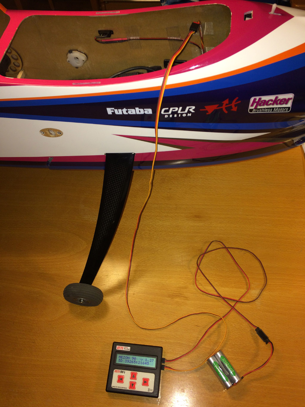
To program the ESC one connect a Jeti Box, with power from an external battery, with a servo lead to a cable from ESC. All changes made via Jeti Box is executed immediately (there is no "Save" button). If You have a Jeti radio You can also program the Jeti ESC from such Jeti transmitter that has Jeti Box emulator.

Futaba/Robbe 150 Amp current sensor 1678 (not made anymore) mounted in fuselage floor just in front of air outlet slot for best possible cooling of the current sensor. The current sensor has small cooling slots on side of the case. Current sensor cable connected to S.BUS hub.
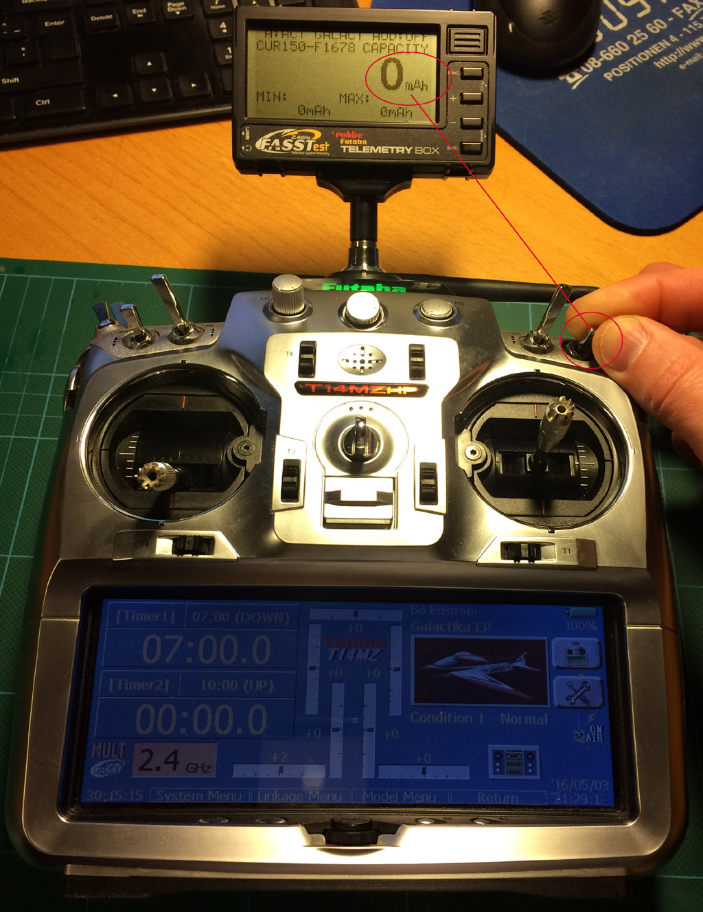
Futaba/Robbe external Telemetry Box F1666 (not made anymore) mounted on my Futaba 14MZ with a bayonet adapter in 35 MHz antenna hole. Capacity (mAh) is reset with switch SD (by flipping it On-Off two times quickly).

One nice side effect with using the Telemetry Box is that the 14MZ ist almost horizontal when hanging in the neckstrap. Without this extra weight (or a 35 MHz antenna mounted and extended) it is very bad center of gravity so TX tilt badly. All who has used a Futaba 14MZ know how annoying that is.
/Bo
ESC:
I'm familiar already with the Jeti-Hacker Master Mezon ESC with BEC that was selected for my Galactika.
I have one in my MythoS Pro already and know how it is mounted in a good way and the settings I use same in Galactika is same as I use in Master Mezon my in MythoS Pro. It was 10 min work to dail in all values in the new Master Mezon in Galactika. Jeti Box is used in my case to configure the ESC.
I use (latest) firmware 1.27 in my Master Mezon ESC.
Master Mezon 90 with BEC was selected for my Galactika despite this ESC is on the heavy side with 140 grams.
One slight irritating feature is that it has an external On-Off switch also, that I selected to mount
on left side of fuselage 40 mm (1.57 in) below middle of canopy. Extending the wires to the On-Off switch was needed.
Master Mezon 90 BEC specification:
Continuous Current: 90A
Voltage range: 5 - 51V
LiPo : 2-12 cells
BEC current : 10 Amp
BEC voltage : 5 - 8V
Dimensions : 36x20x109 mm
Weight : 140 grams
I had checked in another Galactik assembly thread over at Flying Giants
http://www.flyinggiants.com/forums/s...ad.php?t=87621
that Galactik had a tendency to be tail heavy, so I mounted the ESC as far forward in fuselage as possible to be ready for similar tendency in my Galactika.
I mounted the ESC on a plate on fuselage floor that was glued with some red beech pieces where the screws was holding the ESC through rubber grommets. The metal cooling plate on the ESC was exposed very well to air inlet in the nose. No obstacle for the air after it as flowed over the ESC except the current sensor that is placed just in front of the main air exit slot on underside of fuselage.
4 air inlet holes in nose and a rather large air outlet slot under the fuselage provide good cooling for ESC, motor, current sensor and LiPo flight battery.
I have my Master Mezon set to following important values.
Settings menu, Controller Settings:
Operation Mode: Normal
Acceleration 0-100% 0.50 s(sec)
Brake mode, Manual setting:
Brake begin pwr(power): 20%
Brake end pwr: 56%
Break dead time: 0.0 s
Brake speed: 0.3 s
Other ESC settings of importance:
Temp protection: 100 deg C
Max bat. current: 120 Amp
Max bat capac. (capacity): No limit (no motor cut off for max capacity usage)
Cutoff type: Slow down
Cutoff volt per cell: 3.1 volt
Off voltage set: 31.0 volt
SBEC voltage: 7.4 volt
Init. Point Type (throttle ch range): Fixed
Initial point: 1.10 ms (pulse width for trottle ch, measured previously with Jeti Box on throttle ch)
End Point: 2.03 ms (measured previously with Jeti Box on throttle ch)
Current sensor:
The current sensor I use is Futaba/Robbe item no 1678 (discontinued but still available in Germany).
It has proven to work excellent during two seasons in my MythoS Pro.
It has weight of 19 grams.
The sensor has to be upgraded with newer software then factory installed software, to get support for resetting mAh count to zero with a switch on the radio (otherwise reset has do be made with a button on the currecnt sensor). It is easy to upgrade the sensor via USB and a special upgrade program that Robbe made when they where in business.
To get support for the current sensor in Robbe/Futaba external Telemstry Box it has to have software version 1.003 (I had upgraded to that previously, via USB on PC with upgrade software).
The tricky part is to solder the plus cables on the metal solder points inside the current sensor.
You do not want a cold solder here.
But I knew from before when I did this work for the MythoS Pro how it was best done so it was no problem this time. The current sensor has also an external voltage connector and the plus and minus leads is soldered to plus and minus battery leads cables (on ESC side).
The sensor was mounted on a small 1,5 mm plywwod plate with some side support that alowed a gap for small welcro around the sensor case to secure it in place, there is also small welcro pieces under the sensor to help keep it is place.
Sensor is mounted just in front of the air outlet slot so it get very good cooling through it's cooling openings in sensor case.
The sensor record telemetry data for voltage, ampere and capacity (mAh).
The telemetry data from sensor is sent to Futaba R6308SBT receiver via S-BUS2 and receiver send it to the external Futaba/Robbe Telemetry Box that is mounted with a Futaba bayonet adapter in old 35 Mhz antenna hole on my Futaba 14MZ transmitter.
The current sensor is registered in the Telemetry Box by connecting the sensor directly to the Box with a servo lead and then register the sensor in he menu in the Telemetry Box.
This telemetry solution has worked without any problem at all for two seasons with my MythoS Pro.
It is fantastic that I could extend useful life of my Futaba 14MZ this way with telemetry, thanks to Robbe that developed this telemetry in cooperation with Futaba for Futaba FASST radios for the European market.
For me it mean I can use my 14MZ some more years and it will be about 10 years usage before I will retire it (I have used it for 8 years now).
The Telemetry Box has alarms for limits I set in it and can have vibration, speech and sound alarms.
I have a routine to always before a flight check LiPo flight battery voltage (that is around 41-42 volt if fully charged) and then check I have reset the mAh count to zero.
If the Scorpion Backup guard has kicked in I will get an alarm since I have 5.1 volt alarm threshold for receiver voltage (Backup Guard kicks in at 5 voltage and below).
I need no more telemetry then this really for my F3A flying. I feel I really can rely on this telemetry solution, proven by 2 seasons rather much F3A flying including competition flying, also in bad weahter.
Mounting plate for ESC on fuselage floor. Plate is a laminate of Carbon-Herex-Carbon material.
Jeti/Hacker Master Mezon 90 with BEC mounted as far forward as possible to avoid that the plane be tailheavy that it probably in most cases can be if not enough accessories can be mounted rather forward in fuselage. ESC has 4 rubber grommets that it is fastened to the mounting plate with.
ESC front view, excellent cooling capabilites from front air intake and then through the fuselage letting the air flow backwards over the current sensor that can be seen little blurry in the background.
The On-Off switch for the ESC. The lead had to be extended so the switch could be mounted where it is shown. Same switch from outside.
To program the ESC one connect a Jeti Box, with power from an external battery, with a servo lead to a cable from ESC. All changes made via Jeti Box is executed immediately (there is no "Save" button). If You have a Jeti radio You can also program the Jeti ESC from such Jeti transmitter that has Jeti Box emulator.
Futaba/Robbe 150 Amp current sensor 1678 (not made anymore) mounted in fuselage floor just in front of air outlet slot for best possible cooling of the current sensor. The current sensor has small cooling slots on side of the case. Current sensor cable connected to S.BUS hub.
Futaba/Robbe external Telemetry Box F1666 (not made anymore) mounted on my Futaba 14MZ with a bayonet adapter in 35 MHz antenna hole. Capacity (mAh) is reset with switch SD (by flipping it On-Off two times quickly).
One nice side effect with using the Telemetry Box is that the 14MZ ist almost horizontal when hanging in the neckstrap. Without this extra weight (or a 35 MHz antenna mounted and extended) it is very bad center of gravity so TX tilt badly. All who has used a Futaba 14MZ know how annoying that is.
/Bo
Last edited by bem; 05-13-2016 at 10:01 AM.
05-04-2016, 02:19 PM
#25
f) Mounting receiver and Scorpion Backup Guard.
Receiver:
Futaba R6308SBT "FASST with telemetry" receiver is in use in my Galactika.
I use same receiver in my MythoS Pro.
It is only way to get Futaba telemetry with older FASST transmitter like my 14 MZ TX.
This receiver can be converted for s small fee (10 Euro) to a R7008SB FASSTest receiver if one want not to use it as a FASST receiver any more. It can be done by R/C Service & Support Ltd in Germany.
The receiver has 8 ch servo slots and one of them is S.BUS slot, there is also a S.BUS2 slot.
When using S.BUS2 sensors with this receiver it must be set in Normal speed mode with Telemetry On (High speed mode do not work with S.BUS2 telemetry sensors).
How that is done is described in this receiver manual.
There is also a binding process to be done between the receiver and the external Futaba/Robbe Telemetry Box that must be done so they have been binded.
Telemetry Box can have two bindings remembered, no more (if more receivers/models need to be used You have to bind it manually and that will be remembered but still only two last bindings are remembered).
When You look at Galactika fuselage and canopy You may get some doubt how good the signals will be for the receiver in the fuselage. Whole nose back to canopy front opening, whole fuselage botton from nose to air outlet slot just in front of wing tube and up to landing gear exit in fuselage has carbon fibre.
I tried to mount the receiver so the antennas would be away from this carbon area.
So far I have not noticed any problem with the signal.
Since I use all S.BUS2 in my Galactika it was rather easy to install the receiver.
Throttle lead from Master Mezon to CH 6 (that is my throttle ch number in this case) slot in receiver.
S.BUS2 slot on receiver with a thicker twisted Futaba servo lead to first S.BUS hub in fuselage.
And Scorpion Backup Guard connected to one servo slot (slot 7/BAT) in receiver. Thats it.
I had previously, when mounting the servos, assigned the correct CH to each servo with help of Futaba S-Link PC Programmer application.
I use:
CH 1: Elvevator (left)
CH 2: Elevator2 (right)
CH 3: Rudder
CH 4: Aileron (right)
CH 5: Aileron2 (left)
CH 6: Throttle (reversed)
I have "Throttle cut" set in transmitter to be ON with dial LD (the left dial of the 3 dials on top of transmitter) when it is turned max to left, and when turned max to right it is OFF.
Failsafe is also programmed so when signal is lost the control surfaces will stay and throttle is turned off.
Scorpion Backup Guard:
I have used Backup Guard before for two seasons in my MythoS Pro and it has, to the best of my knowledge, never been any problem with it. It needs to be charged now and then but as a principle it will not be on and drain any of it's capacity as long as it do not need to jump in and supply receiver+servos with power.
It is a 2 cell LiPo battery (37 grams) with a special circuit so it kicks in to supply receiver and servos only if voltage drop to 5 volts or below (or BEC fail).
It is an uncomplicated, reasonably light and as it seems by my previous 3 seasons usage in two different F3A planes reliable.
Keep It Simple Stupid, KISS, is a nice description of this backup solution I think.
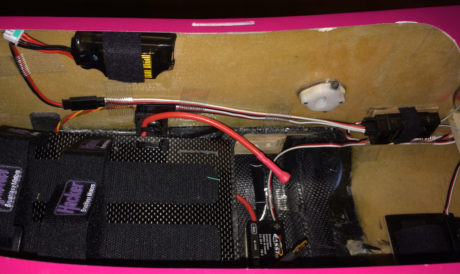
Scorpion Backup Guard mounted just below fuselage canopy edge. Receiver mounted on right side in line with servo cables coming from ESC, Backup Guard and S.BUS hub.

Futaba receiver R6308SBT that is a FASST receiver with telemetry and S.BUS2 allowing the Futaba/Robbe Telemetry Box to be used on transmitter side to view and hear telemetry values and alarms. It can be converted to a R7008SB FASSTest receiver if desired to be used with for example Futaba 18SZ or 18MZ transmitter.
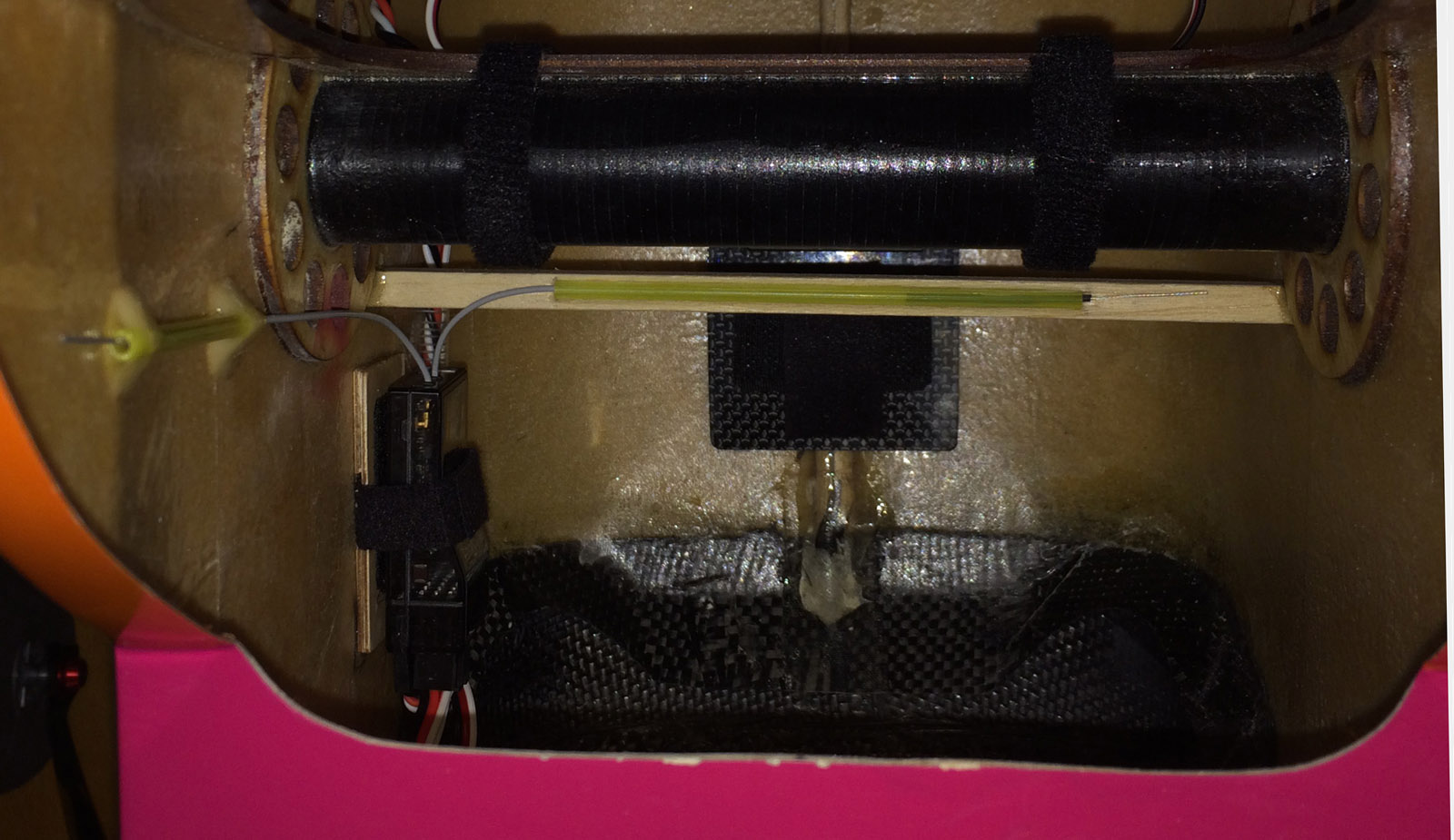
The two receiver antennas, one horizontally and one vertically, exposing the ends (where reception is performed).
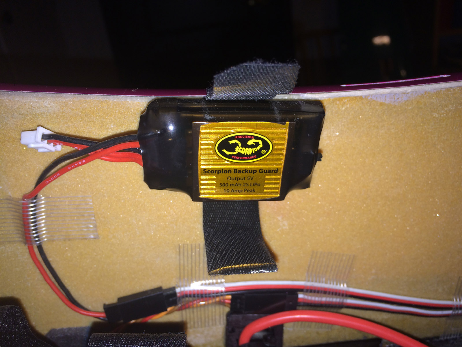
Scorpion Backup Guard. On the right side of it is a small On-Off switch. The rule is to switch ON ordinary power source first (BEC or receiver battery) THEN switch On Backup Guard - the reason is that You want to see that ordinary powersource works.You turn OFF first Backup Guard and then ordinary power source - the reason is same as previously, You want to know that ordinary power source works/has worked. Last ON, first OFF is the rule to remember.

Backup Guard is plugged in to receiver free servo slot and is then ready for use.
It is two ways to charge the Backup Guard: 1) Use an ordinary servo lead (male end) and just use two leads (+ and -) and then charge through the white balancer connector on Backup Guard - the 2 cell LiPo will not be balanced charged then. 2) Use a special charge cable harness with balance connector that can be bought - the LiPo will then be balanced charged.

Here my Backup Guard is balanced charged with the special charge cable harness with balance connector.
/Bo
Receiver:
Futaba R6308SBT "FASST with telemetry" receiver is in use in my Galactika.
I use same receiver in my MythoS Pro.
It is only way to get Futaba telemetry with older FASST transmitter like my 14 MZ TX.
This receiver can be converted for s small fee (10 Euro) to a R7008SB FASSTest receiver if one want not to use it as a FASST receiver any more. It can be done by R/C Service & Support Ltd in Germany.
The receiver has 8 ch servo slots and one of them is S.BUS slot, there is also a S.BUS2 slot.
When using S.BUS2 sensors with this receiver it must be set in Normal speed mode with Telemetry On (High speed mode do not work with S.BUS2 telemetry sensors).
How that is done is described in this receiver manual.
There is also a binding process to be done between the receiver and the external Futaba/Robbe Telemetry Box that must be done so they have been binded.
Telemetry Box can have two bindings remembered, no more (if more receivers/models need to be used You have to bind it manually and that will be remembered but still only two last bindings are remembered).
When You look at Galactika fuselage and canopy You may get some doubt how good the signals will be for the receiver in the fuselage. Whole nose back to canopy front opening, whole fuselage botton from nose to air outlet slot just in front of wing tube and up to landing gear exit in fuselage has carbon fibre.
I tried to mount the receiver so the antennas would be away from this carbon area.
So far I have not noticed any problem with the signal.
Since I use all S.BUS2 in my Galactika it was rather easy to install the receiver.
Throttle lead from Master Mezon to CH 6 (that is my throttle ch number in this case) slot in receiver.
S.BUS2 slot on receiver with a thicker twisted Futaba servo lead to first S.BUS hub in fuselage.
And Scorpion Backup Guard connected to one servo slot (slot 7/BAT) in receiver. Thats it.
I had previously, when mounting the servos, assigned the correct CH to each servo with help of Futaba S-Link PC Programmer application.
I use:
CH 1: Elvevator (left)
CH 2: Elevator2 (right)
CH 3: Rudder
CH 4: Aileron (right)
CH 5: Aileron2 (left)
CH 6: Throttle (reversed)
I have "Throttle cut" set in transmitter to be ON with dial LD (the left dial of the 3 dials on top of transmitter) when it is turned max to left, and when turned max to right it is OFF.
Failsafe is also programmed so when signal is lost the control surfaces will stay and throttle is turned off.
Scorpion Backup Guard:
I have used Backup Guard before for two seasons in my MythoS Pro and it has, to the best of my knowledge, never been any problem with it. It needs to be charged now and then but as a principle it will not be on and drain any of it's capacity as long as it do not need to jump in and supply receiver+servos with power.
It is a 2 cell LiPo battery (37 grams) with a special circuit so it kicks in to supply receiver and servos only if voltage drop to 5 volts or below (or BEC fail).
It is an uncomplicated, reasonably light and as it seems by my previous 3 seasons usage in two different F3A planes reliable.
Keep It Simple Stupid, KISS, is a nice description of this backup solution I think.
Scorpion Backup Guard mounted just below fuselage canopy edge. Receiver mounted on right side in line with servo cables coming from ESC, Backup Guard and S.BUS hub.
Futaba receiver R6308SBT that is a FASST receiver with telemetry and S.BUS2 allowing the Futaba/Robbe Telemetry Box to be used on transmitter side to view and hear telemetry values and alarms. It can be converted to a R7008SB FASSTest receiver if desired to be used with for example Futaba 18SZ or 18MZ transmitter.
The two receiver antennas, one horizontally and one vertically, exposing the ends (where reception is performed).
Scorpion Backup Guard. On the right side of it is a small On-Off switch. The rule is to switch ON ordinary power source first (BEC or receiver battery) THEN switch On Backup Guard - the reason is that You want to see that ordinary powersource works.You turn OFF first Backup Guard and then ordinary power source - the reason is same as previously, You want to know that ordinary power source works/has worked. Last ON, first OFF is the rule to remember.
Backup Guard is plugged in to receiver free servo slot and is then ready for use.
It is two ways to charge the Backup Guard: 1) Use an ordinary servo lead (male end) and just use two leads (+ and -) and then charge through the white balancer connector on Backup Guard - the 2 cell LiPo will not be balanced charged then. 2) Use a special charge cable harness with balance connector that can be bought - the LiPo will then be balanced charged.
Here my Backup Guard is balanced charged with the special charge cable harness with balance connector.
/Bo
Last edited by bem; 05-13-2016 at 10:13 AM.

