


unsucesful launching investigate
 03-17-2018, 10:23 AM
#1
Member
Thread Starter
Join Date: Mar 2005
Location: Shoham, ISRAEL
Posts: 33
Likes: 0
Received 0 Likes
on
0 Posts
Hi guys!
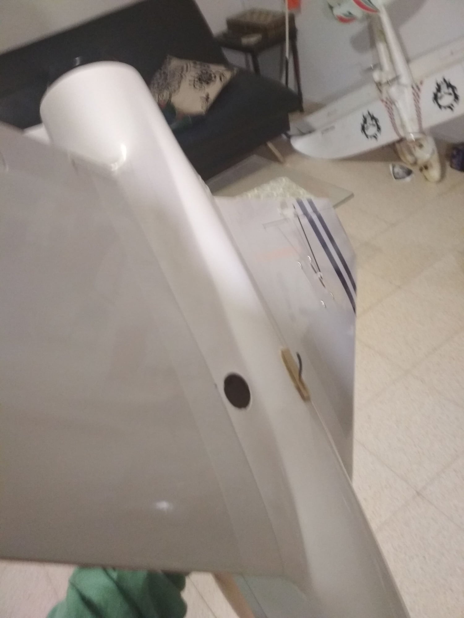
I had bad experience in launching my Spear on test flight.
Im looking for some ideas to fix the issue.
the model weight is 1KG, pretty strong nose wind.
launching video:
It seems like the line got stucked on the model hook, but I can't imagen how it is possible as it should slip out easely.
Im thinking in 2 directions: 1. the bungee or line are to short.
2. I was mistake by install the hook exactely on CG, instead more close to the nose.
many thanks in advance to the advisores,
Tomer
many thanks in advance to the advisores,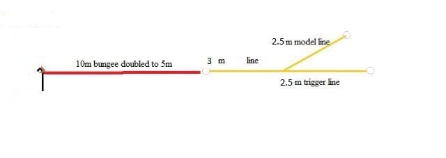
 03-17-2018, 05:24 PM
#2

Join Date: Nov 2010
Location: Coffs Harbour NSW, AUSTRALIA
Posts: 1,563
Likes: 0
Received 71 Likes
on
67 Posts
Why would you waste your time with such riddiculous launching device? Just hand launch it, your model is light enough. But if you insist, badly design hook up system did not release, your hook on the belly is too long, and most importantly I would like to see your hook on the bungee end. You need to simplified it so it will release "150%" each time the model pass the bungee.
 05-07-2018, 01:31 AM
#5
Join Date: Nov 2010
Location: Coffs Harbour NSW, AUSTRALIA
Posts: 1,563
Likes: 0
Received 71 Likes
on
67 Posts
Short article on bungee launching I had just published in some magz. Enjoy reading.
In the "Phantom" mood.
(Hawk day)
"F-4, Phantom" by Fly-Fly was one of my first 90mm EDF jet at the time of the 2.4 gigs. taking over the good old 36 meg. frequency. The stock 6S powered ARF kit was a nice flier at only some 2500 grams AUW, but totaly different performer after later upgrades to 8S, 32+ volts. To keep the weight down, the first one I built I decided to make as a catapult-bungee launcher rather than using the pretty flimsy stock, fixed landing gear.
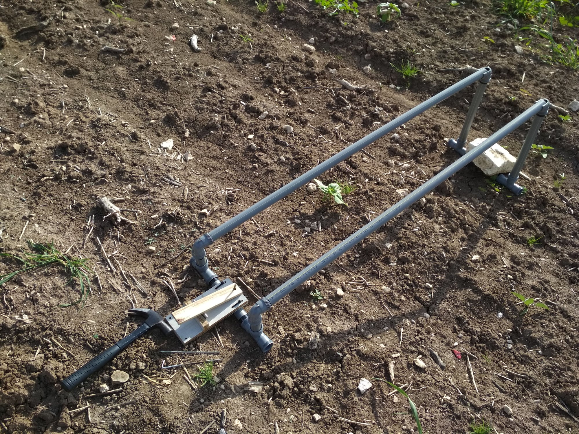
After years of success using my own launch system with the old, very in-efficient brushed motor electric ducted fan jet models and Nicad/NMHi batteries to power them, I have chosen this rather simple way to launch it. During my initial construction before joining the two halfs together a 6mm carbon fiber tube was inbeded and epoxied along the bottom of the frame leaving some 10 cm exposed at the rear as a launch handle, covered with 240 grid sand paper for firm hold. At the front bottom of the frame I have epoxied a long ply wood fin shaped as a small hook some half way between the nose tip and the CofG also serving as a skid and giving extra strength to the frame. I would only assume that the old "F-4s" landing on the carriers had also some reinforcements joining the arrester hook!
Each wing tip was also protected with an additional small fin-skid near the servo mounts to eliminate posibility of servo arm/linkage damage during take off and landings. With this simple set up I use only very short 2-3 meter long rubber cord (surgical rubber tube) attached to 3 to 8 meter long nylon string or similar, and it was only matter of few launches to work out the stretch tension needed for an individual model launch. At various flying sites I often have to launch models in cross or down wind, but with the instant flying speed it wouldn't make any difference beside pulling the bungee little harder on down wind leg.
No need for some impractical launching ramp set ups, I have seen over the years with the most emusing disaster launches, resulting often in total right offs.
With one person operation all I do is secure the bungee pin into the ground, using lot longer pin when launching from the hard packed wet beach sand. I step out, and place my model to required start up position, strech the bungee cord to hook into the nose skid while securely holding the model, advance the full power and let go the handle, "off she goes", usually don't even need use of elevator input as the groung effect does the job of smooth shallow rotation. To prove the effectivness of this system is one of my model, now heading towards 700 flights using this same old technique with not a single failure close to 10 years of action, "90mm BAE Hawk" also by Fly-Fly. (pics) This quite large and lively model at aprx.3 kilograms take off weight, runs on 6S at some 1400-1500 Watts needs only 4 kilogram pull tension of my bungee cord for a 'rocket like' take offs, a lot safer way than hand launches. One of the smaller 64 mm EDF I currently bunge launch at only 850 grams AUW needs some 2.5 kilo tension for a safe catapult just as an example.
Back to the "F-4", and dozens of flights using the reccommended 6S power at some 2.5 kilo AUW I felt for a bit of challenge deciding to hot it up into higher 8S voltage. This time with the use of twin battery pack hooked in series (2x 4S/4000mA) I have installed slightly modified stock landing gear to handle the extra weight of some 3000-3250 grams model. With the new more powerful motor there was a dramatic difference in performance from the original 1.5 K/Watt increased to over 3 KW set up. Unfortunately, it didn't take long when during one of my flights the model while at the furthest distance went in, on full power. Thanks to some tree branches and few shrubs the damage wasn't too bad so after some cosmetic repairs unsure what happened the same thing repeated soon after few more flights, so the bells started to ring there is some serious issue of radio interfeerance.
After few phone calls and discussion with some pilots also changing from the old technology to this new higher voltage EDF set ups I have learned that it is a 'No-No' to use 36 meg. frequency with such high voltage/curent draws as 120 Amps and over. So it was around this time I have purchased a 2.4 ghz. module with few 9ch. receivers to modify my transmitter, back around 2010 when in our Club it was still bit of a novelty.
Next time with the brand new model I was more thorough about my range checks and to my old memory I walked away such a long distance that the model would be hardly visable, but just managed to see some hand signals I have ordered my helper to comunicate with. All good!, after positive tests. Simple fix and the model is still serving well after all these years to this date. Interestingly, there are still many models in my fleet including single and twin powered 90 mm EDF jets I run on 36 meg. SPCM receivers with no issue but I never exeed voltage above 6S lipos.
The good news is, my good old "Phantom" got a new company in form of slightly smaller version from E-flite, after receiving an offer I could not refuse. A real bargain of brand new, partly assembled model even fitted with decent metal gear servos. Again, sort of ARF version with 6S powered 80mm fan/motor combo unit, and 80A, BEC fitted speedo. Fixed landing gear which can be easilly replaced with electric retracts was also part of the kit. At first look, very impressive and shiny looking model but after getting closer at it, built as a "brick"! The factory must have had an excess of fiber glass and resin to get rid off, not mentioning the un-necessary ply wood to ad extra weight. I believe the small frame itself could be easilly half a kilogram lighter if the above material was used more sparingly. It remids me very much of another model, by the same firm "Habu 32", I have been flying for the last four years after some wing tip modifications, also very heavilly built but with more efficient single outlet duct than the twin nozzled Phantom. Nevertheless, good steal for the fraction of replacement costs so I'll try my best to make most of it.
Model comes with a very thorough detailed instruction manual for an average builder to put it together. There is also separate manual for the 80 mm fan/motor assembly and performance data. To start with, I have pulled everything back appart and the first thing upgraded the servo fitment to all control functions. I would never rely on the servos attachments to the stock tiny wooden blocks bonded to the bace plates, so each servo was also bonded securely to the plate with the use of strong flexible industrial agent for the piece of mind and long reliable operation. From my early experience I have found this is a disaster in waiting if not upgraded as these small wooden blocks split easilly over the time after constant twisting and torque action of the servos. There are 7 servos operating, 2 for separate Aileron channel, one larger servo for Elevator, 2 via "Y" lead as flaps, Rudder, and mixed to it is the Nose gear steering servo.
After few test flights when fully satisfied with the model I will install the retractable gear but to start with I use the stock fixed gear.
Next step was the heart of the model, the power plant! The rather long power and motor leads were cut down to minimal length for a neat installation, performance and the larger 5.5mm gold bullet connectors soldered on to fit my batteries. There was no instruction for the ESC with inbuild BEC so I have hooked it all up to give it a little test run resulting in excessive vibration of the fan. Also the throttle movement of my radio did not calibrate well with the ESC, needing the full trim up, before any response. After removal of the unit to do some dynamic ballancing I have noticed the 5 bladed rotor very easilly sliding off from the motor shaft addapter. With my other variety of fans I have found the rotors much tighter fit over the shafts making it much easier to ballance.
Also, founding the conical spinner which serves as a nut to secure the rotor, holding only on few threads of the addapter, limiting further tightening due to its diagnal hole through it. Deciding to use nut and washer instead, I have done slight modification to the rotor by machining off some 3 mm in the front centre to give me extra few threads for firm tighteness. Marking precisely position of the rotor/addapter further test resulted still in excessive vibes. This time I have removed the addapter and also the motor from the shroud trying to find out the root of the problem.
The long can motor had to be packed up at the rear with few layers of alloy tape as there was some free gap instead perfect tight fit in the motor casing. Addapter was moved 3 mm closer to the motor by shortening the motor shaft the same length to minimize vibration. After putting it all back the vibration improved but still not good enough, creating very noisy run. It took me at least five further in and outs of the power unit and re-positioning the rotor on the shaft to get satisfactory smooth running fan, lot of messing around but worth it at the end.
This time I was comfortable to run it on full power for longer periods while hooking up the E-meter to take note of the voltage drop, current draw and wattage. These tests were repeated numerous times while using various brands, capacity and C-rated batteries to compare with the test of the larger 130 Amp, OPTO speed controller. The throttle response and the data improved dramatically so the unit was replaced as I'm going to use an additional 5 cell NMHi battery to operate my functions for the redundancy. During these tests I was also recording the static thrust which normally gives me a good idea about the model's performance in advance. The static thrust figures were rather low for my like due to the twin outlet ducts and even after making up couple of different diameter exhaust nozzels as an experiment I wasn't much impressed. At 1.55 kilo pull, the 3+ kilo AUW model of this size did not sound very convincing. At 60-70 Amp current draw on full power there is a limit on the size of battery capacity to carry and no other way to reduce the over all weight.
So it was back to my old trick, wing load reduction by adding extra winglets to the wing tips. After laminating some sheets of balsa I have shaped up nice winglets and after some paint job were epoxied to the tips in slight diheadral position. Certainly improving the look of the model, at least in my eyes.
There will always be, some scale "kritiks", but in this hobby there is always one priority as far as I'm concerned, "endurance, performance and reliability!", as my priority!
The main wings I normally epoxy pernamently to the frame with small models as this but in this case there is a very good wing attachment method by epoxying CF flat spar into the wing cavity which is cecured by couple of 4 mm bolts inside the fuse, tho bit tricky to access and special spanner tool might come handy to do it. Elevator and the Rudder hook up was simple, just by adjustment of the push rods, but I put bit of a question mark on pre-assembled Elevator control arm which was factory built. Not the most convincing, but it will be one function I will operate with extreme fine touch when flying this model. Other than that, I have done lot of soldering to eliminate any plug-in servo connectors while keeping the lead length to minimal. 9 ch. receiver with satelite was placed well clear from ESC, motor and main power leads at the rear fuselage section working all flalessly after proper range check was done.
Beside few of these improvements there wasn't much to do assembling this model then the regular double check of all functions and the most critical the centre of gravity position. I might mention one of the thing I always pay extra attention to is the power unit duct cover normally just taped over, but I always redesing it so it is well secured with numerous self tappers and sealed off with fiber glass reinforced tape to eliminate any lose of air pressure in the exhaust duct. I have also removed the streamlined motor covering inside the duct which I find only limits fresh airflow over the motor and efficient cooling. The three motor wires exiting I normally cover over with the heat shrink and lead out of the rear duct the shortest, un-obstractive way. Stay tune for further report from Joseph Frost.
In the "Phantom" mood.
"F-4, Phantom" by Fly-Fly was one of my first 90mm EDF jet at the time of the 2.4 gigs. taking over the good old 36 meg. frequency. The stock 6S powered ARF kit was a nice flier at only some 2500 grams AUW, but totaly different performer after later upgrades to 8S, 32+ volts. To keep the weight down, the first one I built I decided to make as a catapult-bungee launcher rather than using the pretty flimsy stock, fixed landing gear.
After years of success using my own launch system with the old, very in-efficient brushed motor electric ducted fan jet models and Nicad/NMHi batteries to power them, I have chosen this rather simple way to launch it. During my initial construction before joining the two halfs together a 6mm carbon fiber tube was inbeded and epoxied along the bottom of the frame leaving some 10 cm exposed at the rear as a launch handle, covered with 240 grid sand paper for firm hold. At the front bottom of the frame I have epoxied a long ply wood fin shaped as a small hook some half way between the nose tip and the CofG also serving as a skid and giving extra strength to the frame. I would only assume that the old "F-4s" landing on the carriers had also some reinforcements joining the arrester hook!
Each wing tip was also protected with an additional small fin-skid near the servo mounts to eliminate posibility of servo arm/linkage damage during take off and landings. With this simple set up I use only very short 2-3 meter long rubber cord (surgical rubber tube) attached to 3 to 8 meter long nylon string or similar, and it was only matter of few launches to work out the stretch tension needed for an individual model launch. At various flying sites I often have to launch models in cross or down wind, but with the instant flying speed it wouldn't make any difference beside pulling the bungee little harder on down wind leg.
No need for some impractical launching ramp set ups, I have seen over the years with the most emusing disaster launches, resulting often in total right offs.
With one person operation all I do is secure the bungee pin into the ground, using lot longer pin when launching from the hard packed wet beach sand. I step out, and place my model to required start up position, strech the bungee cord to hook into the nose skid while securely holding the model, advance the full power and let go the handle, "off she goes", usually don't even need use of elevator input as the groung effect does the job of smooth shallow rotation. To prove the effectivness of this system is one of my model, now heading towards 700 flights using this same old technique with not a single failure close to 10 years of action, "90mm BAE Hawk" also by Fly-Fly. (pics) This quite large and lively model at aprx.3 kilograms take off weight, runs on 6S at some 1400-1500 Watts needs only 4 kilogram pull tension of my bungee cord for a 'rocket like' take offs, a lot safer way than hand launches. One of the smaller 64 mm EDF I currently bunge launch at only 850 grams AUW needs some 2.5 kilo tension for a safe catapult just as an example.
Back to the "F-4", and dozens of flights using the reccommended 6S power at some 2.5 kilo AUW I felt for a bit of challenge deciding to hot it up into higher 8S voltage. This time with the use of twin battery pack hooked in series (2x 4S/4000mA) I have installed slightly modified stock landing gear to handle the extra weight of some 3000-3250 grams model. With the new more powerful motor there was a dramatic difference in performance from the original 1.5 K/Watt increased to over 3 KW set up. Unfortunately, it didn't take long when during one of my flights the model while at the furthest distance went in, on full power. Thanks to some tree branches and few shrubs the damage wasn't too bad so after some cosmetic repairs unsure what happened the same thing repeated soon after few more flights, so the bells started to ring there is some serious issue of radio interfeerance.
After few phone calls and discussion with some pilots also changing from the old technology to this new higher voltage EDF set ups I have learned that it is a 'No-No' to use 36 meg. frequency with such high voltage/curent draws as 120 Amps and over. So it was around this time I have purchased a 2.4 ghz. module with few 9ch. receivers to modify my transmitter, back around 2010 when in our Club it was still bit of a novelty.
Next time with the brand new model I was more thorough about my range checks and to my old memory I walked away such a long distance that the model would be hardly visable, but just managed to see some hand signals I have ordered my helper to comunicate with. All good!, after positive tests. Simple fix and the model is still serving well after all these years to this date. Interestingly, there are still many models in my fleet including single and twin powered 90 mm EDF jets I run on 36 meg. SPCM receivers with no issue but I never exeed voltage above 6S lipos.
The good news is, my good old "Phantom" got a new company in form of slightly smaller version from E-flite, after receiving an offer I could not refuse. A real bargain of brand new, partly assembled model even fitted with decent metal gear servos. Again, sort of ARF version with 6S powered 80mm fan/motor combo unit, and 80A, BEC fitted speedo. Fixed landing gear which can be easilly replaced with electric retracts was also part of the kit. At first look, very impressive and shiny looking model but after getting closer at it, built as a "brick"! The factory must have had an excess of fiber glass and resin to get rid off, not mentioning the un-necessary ply wood to ad extra weight. I believe the small frame itself could be easilly half a kilogram lighter if the above material was used more sparingly. It remids me very much of another model, by the same firm "Habu 32", I have been flying for the last four years after some wing tip modifications, also very heavilly built but with more efficient single outlet duct than the twin nozzled Phantom. Nevertheless, good steal for the fraction of replacement costs so I'll try my best to make most of it.
Model comes with a very thorough detailed instruction manual for an average builder to put it together. There is also separate manual for the 80 mm fan/motor assembly and performance data. To start with, I have pulled everything back appart and the first thing upgraded the servo fitment to all control functions. I would never rely on the servos attachments to the stock tiny wooden blocks bonded to the bace plates, so each servo was also bonded securely to the plate with the use of strong flexible industrial agent for the piece of mind and long reliable operation. From my early experience I have found this is a disaster in waiting if not upgraded as these small wooden blocks split easilly over the time after constant twisting and torque action of the servos. There are 7 servos operating, 2 for separate Aileron channel, one larger servo for Elevator, 2 via "Y" lead as flaps, Rudder, and mixed to it is the Nose gear steering servo.
After few test flights when fully satisfied with the model I will install the retractable gear but to start with I use the stock fixed gear.
Next step was the heart of the model, the power plant! The rather long power and motor leads were cut down to minimal length for a neat installation, performance and the larger 5.5mm gold bullet connectors soldered on to fit my batteries. There was no instruction for the ESC with inbuild BEC so I have hooked it all up to give it a little test run resulting in excessive vibration of the fan. Also the throttle movement of my radio did not calibrate well with the ESC, needing the full trim up, before any response. After removal of the unit to do some dynamic ballancing I have noticed the 5 bladed rotor very easilly sliding off from the motor shaft addapter. With my other variety of fans I have found the rotors much tighter fit over the shafts making it much easier to ballance.
Also, founding the conical spinner which serves as a nut to secure the rotor, holding only on few threads of the addapter, limiting further tightening due to its diagnal hole through it. Deciding to use nut and washer instead, I have done slight modification to the rotor by machining off some 3 mm in the front centre to give me extra few threads for firm tighteness. Marking precisely position of the rotor/addapter further test resulted still in excessive vibes. This time I have removed the addapter and also the motor from the shroud trying to find out the root of the problem.
The long can motor had to be packed up at the rear with few layers of alloy tape as there was some free gap instead perfect tight fit in the motor casing. Addapter was moved 3 mm closer to the motor by shortening the motor shaft the same length to minimize vibration. After putting it all back the vibration improved but still not good enough, creating very noisy run. It took me at least five further in and outs of the power unit and re-positioning the rotor on the shaft to get satisfactory smooth running fan, lot of messing around but worth it at the end.
This time I was comfortable to run it on full power for longer periods while hooking up the E-meter to take note of the voltage drop, current draw and wattage. These tests were repeated numerous times while using various brands, capacity and C-rated batteries to compare with the test of the larger 130 Amp, OPTO speed controller. The throttle response and the data improved dramatically so the unit was replaced as I'm going to use an additional 5 cell NMHi battery to operate my functions for the redundancy. During these tests I was also recording the static thrust which normally gives me a good idea about the model's performance in advance. The static thrust figures were rather low for my like due to the twin outlet ducts and even after making up couple of different diameter exhaust nozzels as an experiment I wasn't much impressed. At 1.55 kilo pull, the 3+ kilo AUW model of this size did not sound very convincing. At 60-70 Amp current draw on full power there is a limit on the size of battery capacity to carry and no other way to reduce the over all weight.
So it was back to my old trick, wing load reduction by adding extra winglets to the wing tips. After laminating some sheets of balsa I have shaped up nice winglets and after some paint job were epoxied to the tips in slight diheadral position. Certainly improving the look of the model, at least in my eyes.
There will always be, some scale "kritiks", but in this hobby there is always one priority as far as I'm concerned, "endurance, performance and reliability!", as my priority!
The main wings I normally epoxy pernamently to the frame with small models as this but in this case there is a very good wing attachment method by epoxying CF flat spar into the wing cavity which is cecured by couple of 4 mm bolts inside the fuse, tho bit tricky to access and special spanner tool might come handy to do it. Elevator and the Rudder hook up was simple, just by adjustment of the push rods, but I put bit of a question mark on pre-assembled Elevator control arm which was factory built. Not the most convincing, but it will be one function I will operate with extreme fine touch when flying this model. Other than that, I have done lot of soldering to eliminate any plug-in servo connectors while keeping the lead length to minimal. 9 ch. receiver with satelite was placed well clear from ESC, motor and main power leads at the rear fuselage section working all flalessly after proper range check was done.
Beside few of these improvements there wasn't much to do assembling this model then the regular double check of all functions and the most critical the centre of gravity position. I might mention one of the thing I always pay extra attention to is the power unit duct cover normally just taped over, but I always redesing it so it is well secured with numerous self tappers and sealed off with fiber glass reinforced tape to eliminate any lose of air pressure in the exhaust duct. I have also removed the streamlined motor covering inside the duct which I find only limits fresh airflow over the motor and efficient cooling. The three motor wires exiting I normally cover over with the heat shrink and lead out of the rear duct the shortest, un-obstractive way. Stay tune for further report from Joseph Frost.
05-07-2018, 03:08 PM
#6

Join Date: Oct 2008
Location: , AUSTRALIA
Posts: 424
Likes: 0
Received 0 Likes
on
0 Posts
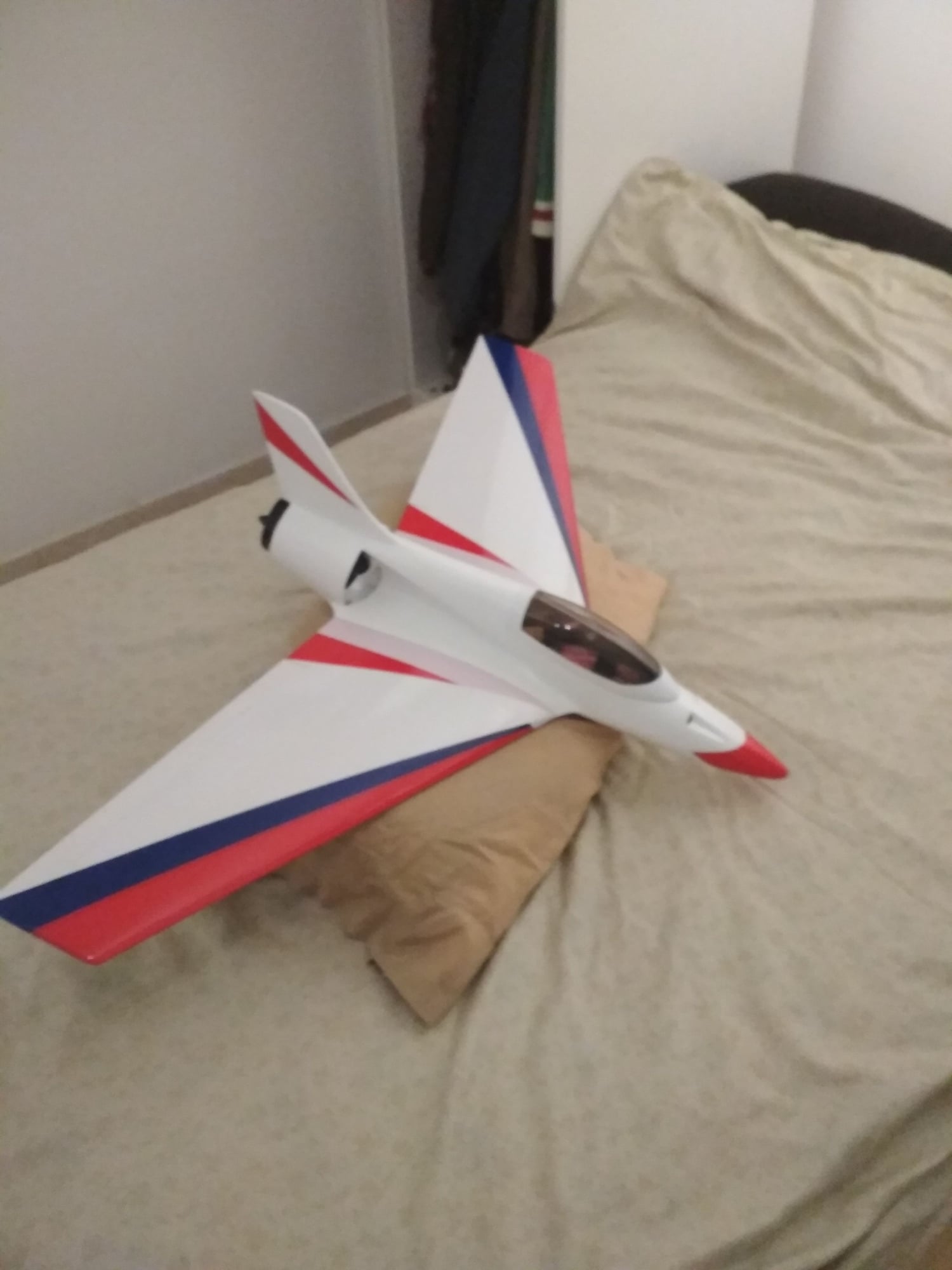
You don't need separate lines for model and trigger, all you need is a first loop that hooks onto the model, then a second hoop on the same line back back a little that hooks to the pedal. You should move the pedal back away from the ramp a bit and stake it in separately if required. Use key rings for the loops, sand and solder them up so they are solid.
Your hook is in the wrong spot and is the wrong shape, it should be squared off, so it comes out of your fuse vertical then a sharp 90 degree bend back, 10mm down is more than enough, then 15-20mm back, and put it 2 inches in front of your CG. Should work fine if you set it all up this way.
Your hook is in the wrong spot and is the wrong shape, it should be squared off, so it comes out of your fuse vertical then a sharp 90 degree bend back, 10mm down is more than enough, then 15-20mm back, and put it 2 inches in front of your CG. Should work fine if you set it all up this way.
Last edited by Extreme_RC; 05-07-2018 at 03:10 PM.
05-08-2018, 12:26 AM
#7
Join Date: Nov 2010
Location: Coffs Harbour NSW, AUSTRALIA
Posts: 1,563
Likes: 0
Received 71 Likes
on
67 Posts
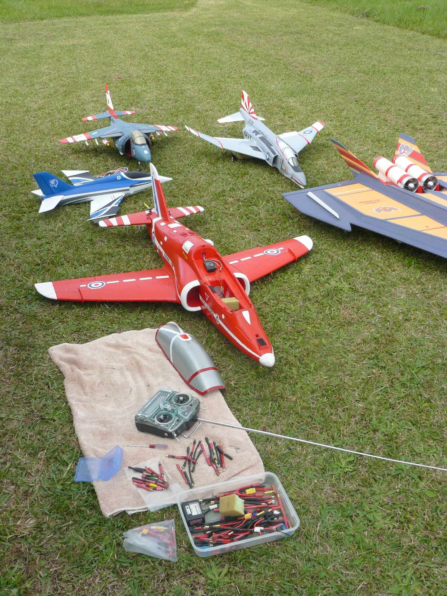
Another perfect flying day with few EDFs of every size and caliber. (64/70/80 and 90s)
Never use a key ring and the type of hook as pictured in the first post, it is a disaster in waiting!, as seen in the video, I have seen it too many times. I'm closing on "700th." catapult launch with my"Hawk", not a single failure so far speaks for itself. Few more flights today in perfect Autumn conditions, the footage shows how efficient the system works even during down wind launch. Enjoy.
