


Homelite (and other) Hop Up Techniques and How To:
 03-19-2015, 04:56 PM
#1

[h=1]HOMELITE 25cc HOP UP[/h]
This article is specifically about the Homelite 25cc, and pertains to the Homelite 30cc engine in most respects as well. However, the port measuring and porting techniques apply equally well to most small two stroke engines. I hope you find it helpful.
First and foremost, it is important that one never attempt to “hop up” a worn engine. The results will be frustrating at best. All important components should be in perfect condition, and I always recommend starting with a new Frank Bowman ring as well. I have seen engines that still ran pretty well gain 800 rpms by only replacing a worn ring.
Second, a coordinated approach is always needed when hopping up any engine. The modifications need to work together to achieve good results. It does no good to bolt on a huge carburetor for example, and leave the stock, restrictive exhaust in place. Common errors such as this create an engine that actually runs worse than stock.
Third, unless you are willing to go through a lot of parts and do a lot of testing, stick to known, proven modifications. Parts cost a lot of money, and if you make a modification that doesn’t work, well, you just created an expensive paper weight. Don’t re-invent the wheel….
And lastly, don’t “polish” the ports. Just a nice finish with a small sanding drum to clean up the casting is all that is necessary. “Polishing the Ports” is old tech, and it has been proven that a slightly rough port actually flows somewhat better than a mirror smooth port. Seems odd, but it’s not if you know some of the intricacies of fluid dynamics.
You will need the proper tools of course. Torx drivers, screwdrivers, etc., etc. as normal, plus a few special tools. Here are some that I use:
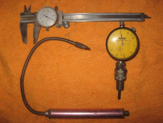
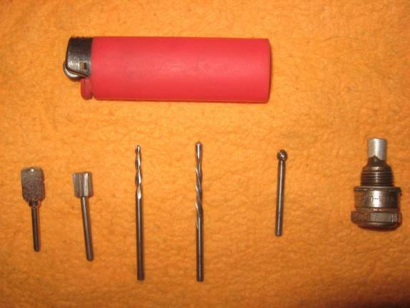
Most of them are self explanatory. The small light on the end of a flex cable is my favorite for checking port timing as I can insert it inside the engine and really see when a port opens or closes. The Dremel cutters are all carbide. Don’t try to use grinding stones on aluminum or magnesium! They will immediately clog up, then can over heat and explode! Lastly for the Dremel is a small sanding drum tool. (Good for final dressing up of the ports.) The tool that looks like a spark plug is my Positive Stop for finding TDC, (Top Dead Center), and the last is a length of PVC tubing with a piece of thick, hard emery sand paper securely glued onto the end. This is for removing the squish band. A person should also have some small jeweler’s files in flat and round. They should be heated and have the last 1.5” or so bent at about a 20 to 30 degree angle. These are for dressing and chamfering the edges of the ports to prevent damage to the piston and/or ring. I do it with the small round carbide tool in my Dremel, but, one slip and, well, remember what I said about expensive paper weights?
I don’t need to mention about eye protection and a dust mask for use while porting and grinding on metal do I? Didn’t think so….
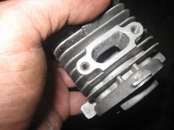
The first step, after disassembly, and a thorough cleaning and inspection of parts, is to mock up the engine the first time to take baseline measurements. Hopefully, we already have the Frank Bowman modified piston and special ring in hand. Then we start taking our baseline measurements, but one of the measurements will require the squish band to be removed first, so I do that using the PVC tube with the stiff sand paper glued on it. The PVC tube is a nice smooth slip fit into the cylinder. One could make a special cutter to do this, but unless you do a lot of engines it wouldn’t be worth it. Just use the sand paper tool. Push it up against the squish band and push and turn to remove the band. Check often, and be very careful not to scar or score the cylinder bore with the tool. You are done when you can insert a screwdriver or scribe into the cylinder head area, and no longer feel that “step” around the outer edge of the combustion area. Here is the cylinder with the squish band ground out.
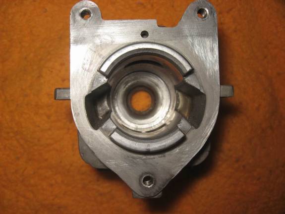
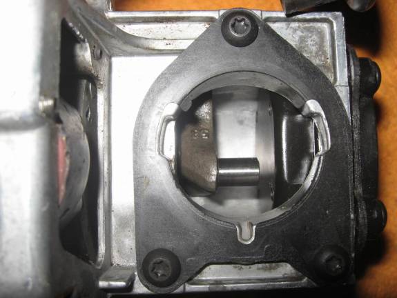
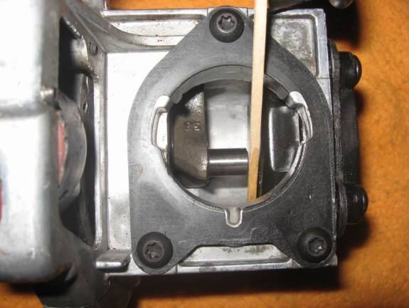
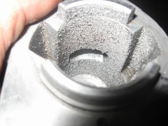
Another thing we are going to be doing is to “stuff the crankcase”, and now is a good time to take a measurement of that to see what will be required. As you can see, there is quite a large gap between the crank pin and the backing plate. We want to reduce that to about .025” for better engine efficiency. (Increased secondary compression ratio.)
Now we can do the first mock up assembly and start taking actual measurements.
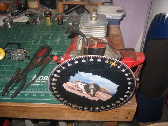
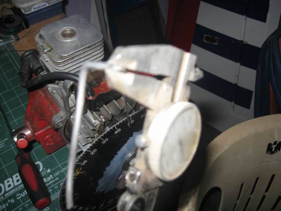
First we set up the degree wheel and pointer by finding TDC. This is the only proper way to find Top Dead Center of the piston, and is called the “Positive Stop Method”. You install your positive stop, (seen screwed into the head in the picture above), and set the degree wheel and pointer so that it shows the exact same degree reading whether the piston is up against the stop going in one direction, or the other. In this case the piston hits the stop at 35 degrees when I rotate the engine clockwise, and when I rotate the engine all the way around counterclockwise and the piston hits the stop again, it also shows exactly 35 degrees. You move the degree wheel or the pointer as necessary to achieve this; equal in both directions. Now, and only now, when you take the Positive Stop out and the pointer shows “TDC”, the piston is actually and truly at Top Dead Center. Now we can take the port timing measurements. Here’s what I got for stock readings:
INTAKE OPEN: 60 degrees BTDC
INTAKE CLOSE: 60 degrees ATDC
Total Duration = 120 degrees
EXHAUST OPEN: 106 ATDC
EXHAUST CLOSE: 74 ABDC
Total Duration = 148 degrees
A special note here because I know people will ask. Here’s how you find that exhaust duration:
180 – 106 = 74 degrees. 74 (from ATDC to BDC) + 74 (ABDC) = 148 total degrees the exhaust port is open. If it is easier for you, just count the total open degrees on the degree wheel.
This is just a baseline measurement. This is an older engine, so the exhaust duration is not too bad. Newer engines have been coming out generally with a much lower exhaust port duration. However, the intake duration is rather low. All this will change however, when we lower the cylinder to raise the compression. When the cylinder is lowered, the exhaust port timing is lowered, and the intake port timing is raised. (The exhaust port will open later, and close earlier, and the intake will do the reverse when the cylinder is lowered.) So when we lower the cylinder, we will lose ground with the exhaust port total timing, but gain some with the intake. We’ll compensate when we do our porting.
Next, while working with the degree wheel in this first mockup, I like to use my dial indicator to see how much piston movement affects port timing. This could be figured out mathematically using the piston stroke, rod length, and some tricky math, but it is quick and easy to do it with the dial indicator, and fool proof.
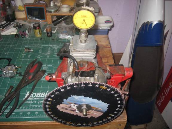
I measure how many degrees of wheel movement it takes to move the dial indicator .100”. (For best accuracy do this test measurement with the piston at about mid travel, and don’t try to figure for just one degree or a smaller dial indicator amount as it won’t be as accurate; use .100”.) In this case, 10 degrees of wheel movement moved the dial indicator .100”. So dividing 10 into .100”, we find that each degree of the wheel moves the piston .010”. That’s a nice easy number to work with. Now, here is an important fact that is absolutely imperative to remember when working with two strokes. Whatever amount you take off a port top or bottom to change the timing DOUBLES the timing change. This is because you are not only changing when the port opens, but also when the port closes.
Example:
20 degree change desired.
20 x .010” = .200”
.200” divided by 2 =.100” (Because both opening AND closing is changed.)
.100” to remove from port opening edge for a 20 degree timing change.
So now we know that in order to make a (for example) 20 degree port timing change, we would remove .100” from the top of the exhaust port or the bottom of the intake port. If we removed .200” it would change the timing 40 degrees because remember, when we make a change to a port, it alters BOTH the opening AND the closing of the port.
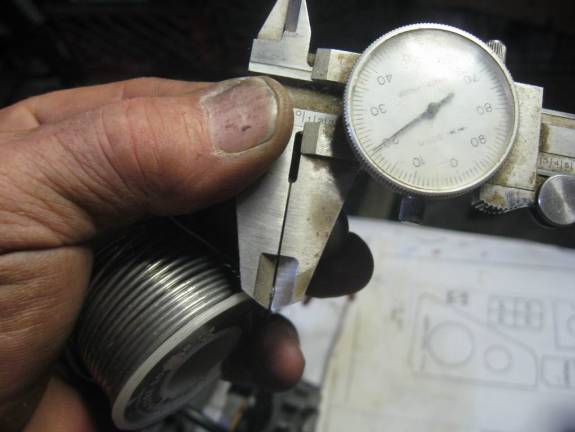
The next thing to check/measure, is the quench or squish distance. This is also sometimes called “Deck Height”, though that term is not exactly correct for this application. What we need to know is the distance from the piston to the head at TDC. The way to do that is to bend a piece of soft solder, (not silver solder) so that it will go into the spark plug hole and go over against the cylinder wall. We then rotate the engine several times while holding the solder secure in one position and making sure it is touching the cylinder wall. The piston will smash the solder flat, which we can then measure and this gives us the piston to head clearance. I normally use 1/8” electrical solder for this, but the clearance was so wide in this engine that I had to use larger diameter plumbing solder. The pic is a bit blurry, but you can see from the gap in the calipers that it was a large piston to head clearance. It measured about .080”, while we want a much smaller gap of .020”. (.015” absolute minimum for safe operation.) Lowering the cylinder and closing up this wide gap will give a nice raise in the compression ratio of this engine. Now we know about how much to remove.
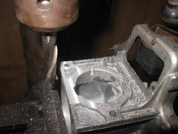
So, the crankcase is set up in the milling machine, and we proceed to take off .060” to arrive at the .020” clearance that we want. (I actually took a bit more off, because I like to make a new, slightly thicker cylinder base gasket and so I allowed for that.) Some people make up a spud to mount the cylinder in a lathe, and remove material from the cylinder base. I prefer to take the material off the crankcase when possible, because then if you ever have to replace the cylinder, you won’t have to do the machine work again. The squish clearance can always be fine tuned with different thickness gaskets if you take enough off the crankcase to allow for that.
Next comes the cylinder porting. There are several important items to note here. One is obvious but critical; you can always take more material off, but you can’t add it back on. So I recommend that you take perhaps half of what you calculated you would need to, and then mock the engine up again, and measure your port timings. See if they are what would be expected for the amount you took off. If you go too far, well, there we are with a paper weight again! You might want to do the porting in three stages instead of just two. Grind a little, check, grind again. (Hey, if it were quick and easy anyone could do it right??!!)
Another thing is that you must always clean up and chamfer the port edges after grinding on them and before mocking the engine up again. If not, the raw port edges where you ground them will scar, score, and destroy the piston and ring. (More paper weights!) It is your choice whether you remove the ring or not for these mock up tests. If you do, be careful as it is very, very easy to break a ring while taking it off or putting it back on. If you don’t take it off, just be very careful when assembling the engine that you don’t break the ring. Go slow and easy, if anything needs forced, something is not right.
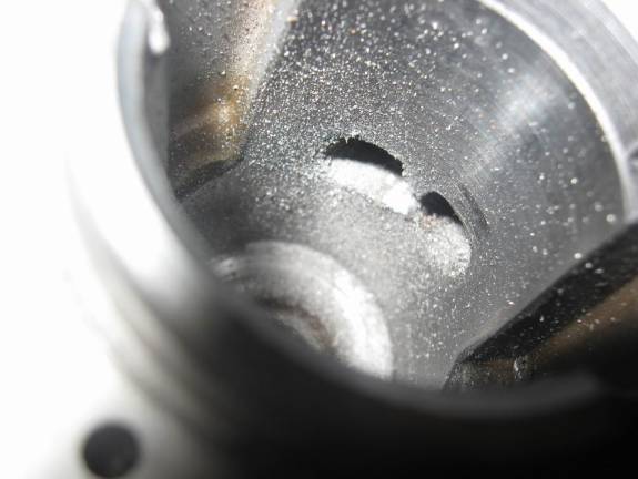
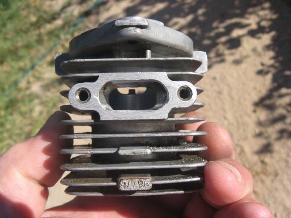
So the Homelite 25cc comes with a bridged exhaust port. We have had the piston modified with a pin and a special ring for use with a pinned piston, all done by the Ring Master, Frank Bowman, so we can remove that port bridge for better exhaust flow. The pin will keep the ring from rotating and ever getting caught in the exhaust port, so, away with that bridge!
As a quick side note here, that is the quick and easy way to tell a Homelite 25cc from a Homelite 30cc. They are identical on the outside, but the 30cc does not have an exhaust port bridge.
Some of the later model Homelite 25 and 30cc engines have a hole in the cylinder just above the exhaust port that leads into a corresponding hole in the muffler. Opinions vary as to what that hole is for, but the most probable one is that it is for EGR, or Exhaust Gas Recirculation. We don’t want that for our engines, so if yours has that, drill and tap it for a set screw, and plug the hole with a set screw with Loctite. Take care that you don’t penetrate the cylinder with the tap threads, as that may cause a burr in the cylinder.
Now for the actual porting. There are several ways to mark the ports for grinding, and I have used them all at one time or another. One is to use magic marker or machinist’s Dykem to color the area above or below the port so that it will show a scribed mark. You can then very, very carefully position the piston so that it’s top edge will be where you want the new top of the port to be, and reach in through the spark plug hole and scribe the cylinder near the port, using the piston as a guide. Another is to do the same magic marker or Dykem marking, but use a calipers to get your distance, and then use a right angle scribe to make your mark. And lastly, you can also use a piece of pin striping tape or a similar piece of tape cut from electrical tape. Use a long tweezers or medical hemostats, and position the tape the appropriate distance above or below the port. You can then grind to your mark, (or the tape), but as I mentioned I highly recommend going only part way and doing an engine mock up and measuring/checking your results and progress. Remember, when changing port timing we ALWAYS remove only from the TOP of the exhaust port, or the BOTTOM of the intake port. All in all I recommend the tape method as probably being the easiest and most fool proof means of marking your port for grinding. Using the bottom of a vernier calipers or using a dial indicator are ways of gauging the distance; another would be to find or make something of the thickness desired, to gauge the distance you want to grind the port top or bottom. It really is difficult working up in that small diameter cylinder with a head that can’t be removed. So just take your time and as I keep saying; go slow and check your work often. Here are some porting pics.
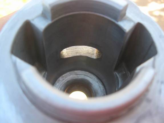
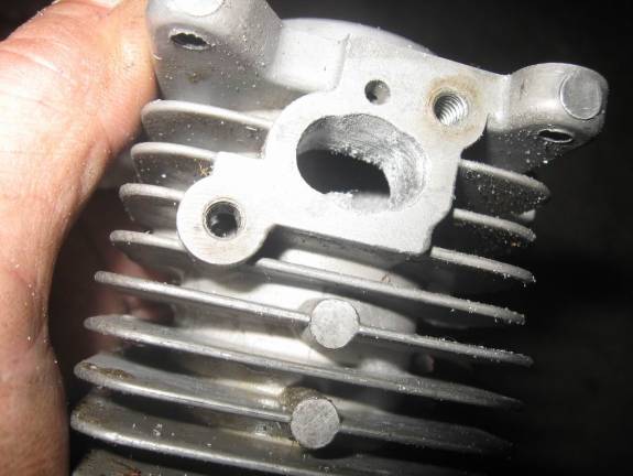
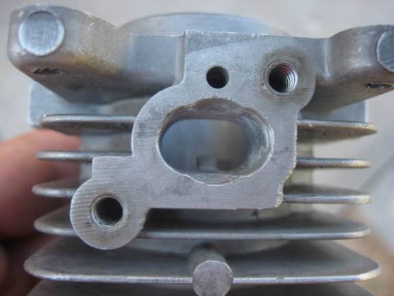
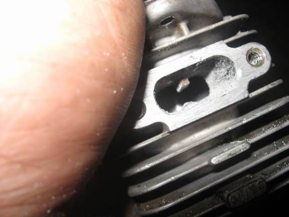
Resist the urge to grind out that little “nub” in the intake port. It is there to help keep the piston ring from bulging into the intake port and getting damaged. Leave it there. Also, the transfer ports are not addressed in this treatise, because they are very critical and you should only attempt modifying them after you are very adept at porting. They must be kept identical, both in opening times, and ANGLES! If you mess them up, the engine might end up running worse than stock. Just check that the transfer ports align at the cylinder to crankcase interface, and smooth the transfer port entry slots in the crankcase itself.
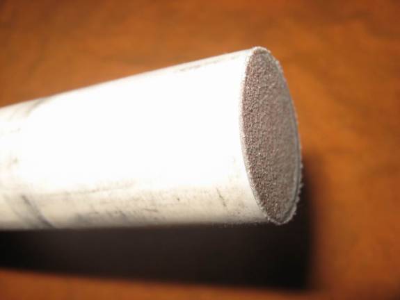
Now we will address “Stuffing the Crankcase.” I determined that a 1/8” piece of aluminum would be the correct thickness to get the .025” crank pin to backplate clearance I wanted, so I made a plate out of it to the shape of the inner surface of the backplate.
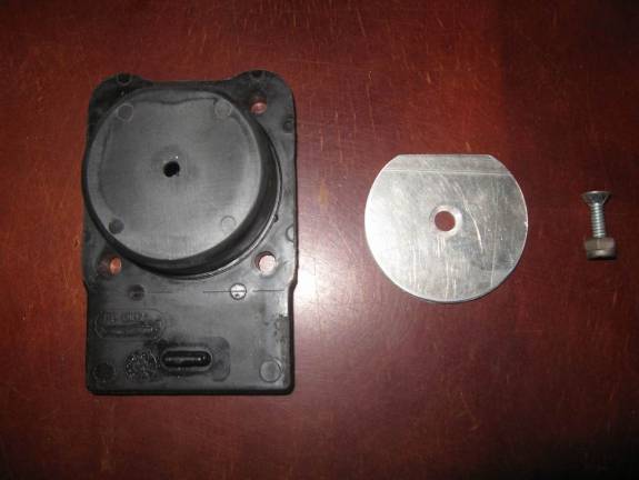
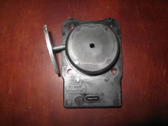
I sanded both the back plate and the aluminum spacer, cleaned them with acetone, and then installed the spacer using JB Weld and a counter sunk screw in the middle. A counter sunk screw is not really needed as the crank pin goes around the middle and won’t hit a bolt head. However, if you use a regular bolt, be sure to check that it doesn’t hit the connecting rod. If you think you will ever need a crankcase pressure tap for a smoke pump, or remote carb pulse, here would be a good place and time to put one. Use the pressure tap to help hold the plate in place instead of a bolt. The JB Weld actually does the holding, the bolt is just there to firmly hold the plate in place while the JB Weld dries, and to help me sleep better at night. It sure would be messy if that plate ever came loose while the engine was running….
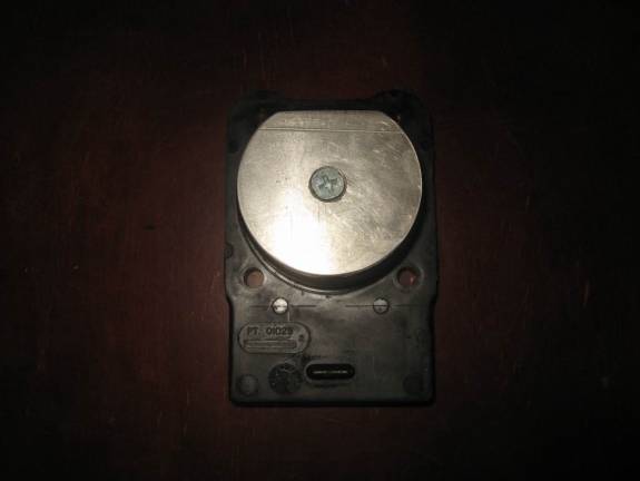
Now we have a much more reasonable piston to crankpin clearance and our crankcase is STUFFED! Note that this is another spot where you can fine tune your clearance with gaskets. Using thicker, thinner, and/or multiple gaskets on the backplate will get you where you want to be; .025”.
Now on to final assembly and the last checks. Use a small amount of two stroke oil on all bearings and give them a spin. Don’t load the engine up, just a few drops on each bearing is plenty.
A pic of the thicker cylinder gasket I made. (use notebook cardboard, cereal boxes, file folders, etc. to make gaskets.) Harbor Freight sells a really neat hole punch kit that makes making gaskets fun. (Well, sort of….)
I don’t use any sealer on the base gasket normally, and NEVER use any sealer on the carb adapter or carb gaskets.
Put a nice film of two stroke oil on the piston, ring, and cylinder wall and put ‘er back together for the last time. (Hopefully!)
With the cylinder bolted on, a final check of the squish distance shows a perfect .020”.
This article is continued in the next post by w8ye. The reason being for the continuation is due to the limitations of the RCU editor . . .
This article is specifically about the Homelite 25cc, and pertains to the Homelite 30cc engine in most respects as well. However, the port measuring and porting techniques apply equally well to most small two stroke engines. I hope you find it helpful.
First and foremost, it is important that one never attempt to “hop up” a worn engine. The results will be frustrating at best. All important components should be in perfect condition, and I always recommend starting with a new Frank Bowman ring as well. I have seen engines that still ran pretty well gain 800 rpms by only replacing a worn ring.
Second, a coordinated approach is always needed when hopping up any engine. The modifications need to work together to achieve good results. It does no good to bolt on a huge carburetor for example, and leave the stock, restrictive exhaust in place. Common errors such as this create an engine that actually runs worse than stock.
Third, unless you are willing to go through a lot of parts and do a lot of testing, stick to known, proven modifications. Parts cost a lot of money, and if you make a modification that doesn’t work, well, you just created an expensive paper weight. Don’t re-invent the wheel….
And lastly, don’t “polish” the ports. Just a nice finish with a small sanding drum to clean up the casting is all that is necessary. “Polishing the Ports” is old tech, and it has been proven that a slightly rough port actually flows somewhat better than a mirror smooth port. Seems odd, but it’s not if you know some of the intricacies of fluid dynamics.
You will need the proper tools of course. Torx drivers, screwdrivers, etc., etc. as normal, plus a few special tools. Here are some that I use:
Most of them are self explanatory. The small light on the end of a flex cable is my favorite for checking port timing as I can insert it inside the engine and really see when a port opens or closes. The Dremel cutters are all carbide. Don’t try to use grinding stones on aluminum or magnesium! They will immediately clog up, then can over heat and explode! Lastly for the Dremel is a small sanding drum tool. (Good for final dressing up of the ports.) The tool that looks like a spark plug is my Positive Stop for finding TDC, (Top Dead Center), and the last is a length of PVC tubing with a piece of thick, hard emery sand paper securely glued onto the end. This is for removing the squish band. A person should also have some small jeweler’s files in flat and round. They should be heated and have the last 1.5” or so bent at about a 20 to 30 degree angle. These are for dressing and chamfering the edges of the ports to prevent damage to the piston and/or ring. I do it with the small round carbide tool in my Dremel, but, one slip and, well, remember what I said about expensive paper weights?
I don’t need to mention about eye protection and a dust mask for use while porting and grinding on metal do I? Didn’t think so….
The first step, after disassembly, and a thorough cleaning and inspection of parts, is to mock up the engine the first time to take baseline measurements. Hopefully, we already have the Frank Bowman modified piston and special ring in hand. Then we start taking our baseline measurements, but one of the measurements will require the squish band to be removed first, so I do that using the PVC tube with the stiff sand paper glued on it. The PVC tube is a nice smooth slip fit into the cylinder. One could make a special cutter to do this, but unless you do a lot of engines it wouldn’t be worth it. Just use the sand paper tool. Push it up against the squish band and push and turn to remove the band. Check often, and be very careful not to scar or score the cylinder bore with the tool. You are done when you can insert a screwdriver or scribe into the cylinder head area, and no longer feel that “step” around the outer edge of the combustion area. Here is the cylinder with the squish band ground out.
Another thing we are going to be doing is to “stuff the crankcase”, and now is a good time to take a measurement of that to see what will be required. As you can see, there is quite a large gap between the crank pin and the backing plate. We want to reduce that to about .025” for better engine efficiency. (Increased secondary compression ratio.)
Now we can do the first mock up assembly and start taking actual measurements.
First we set up the degree wheel and pointer by finding TDC. This is the only proper way to find Top Dead Center of the piston, and is called the “Positive Stop Method”. You install your positive stop, (seen screwed into the head in the picture above), and set the degree wheel and pointer so that it shows the exact same degree reading whether the piston is up against the stop going in one direction, or the other. In this case the piston hits the stop at 35 degrees when I rotate the engine clockwise, and when I rotate the engine all the way around counterclockwise and the piston hits the stop again, it also shows exactly 35 degrees. You move the degree wheel or the pointer as necessary to achieve this; equal in both directions. Now, and only now, when you take the Positive Stop out and the pointer shows “TDC”, the piston is actually and truly at Top Dead Center. Now we can take the port timing measurements. Here’s what I got for stock readings:
INTAKE OPEN: 60 degrees BTDC
INTAKE CLOSE: 60 degrees ATDC
Total Duration = 120 degrees
EXHAUST OPEN: 106 ATDC
EXHAUST CLOSE: 74 ABDC
Total Duration = 148 degrees
A special note here because I know people will ask. Here’s how you find that exhaust duration:
180 – 106 = 74 degrees. 74 (from ATDC to BDC) + 74 (ABDC) = 148 total degrees the exhaust port is open. If it is easier for you, just count the total open degrees on the degree wheel.
This is just a baseline measurement. This is an older engine, so the exhaust duration is not too bad. Newer engines have been coming out generally with a much lower exhaust port duration. However, the intake duration is rather low. All this will change however, when we lower the cylinder to raise the compression. When the cylinder is lowered, the exhaust port timing is lowered, and the intake port timing is raised. (The exhaust port will open later, and close earlier, and the intake will do the reverse when the cylinder is lowered.) So when we lower the cylinder, we will lose ground with the exhaust port total timing, but gain some with the intake. We’ll compensate when we do our porting.
Next, while working with the degree wheel in this first mockup, I like to use my dial indicator to see how much piston movement affects port timing. This could be figured out mathematically using the piston stroke, rod length, and some tricky math, but it is quick and easy to do it with the dial indicator, and fool proof.
I measure how many degrees of wheel movement it takes to move the dial indicator .100”. (For best accuracy do this test measurement with the piston at about mid travel, and don’t try to figure for just one degree or a smaller dial indicator amount as it won’t be as accurate; use .100”.) In this case, 10 degrees of wheel movement moved the dial indicator .100”. So dividing 10 into .100”, we find that each degree of the wheel moves the piston .010”. That’s a nice easy number to work with. Now, here is an important fact that is absolutely imperative to remember when working with two strokes. Whatever amount you take off a port top or bottom to change the timing DOUBLES the timing change. This is because you are not only changing when the port opens, but also when the port closes.
Example:
20 degree change desired.
20 x .010” = .200”
.200” divided by 2 =.100” (Because both opening AND closing is changed.)
.100” to remove from port opening edge for a 20 degree timing change.
So now we know that in order to make a (for example) 20 degree port timing change, we would remove .100” from the top of the exhaust port or the bottom of the intake port. If we removed .200” it would change the timing 40 degrees because remember, when we make a change to a port, it alters BOTH the opening AND the closing of the port.
The next thing to check/measure, is the quench or squish distance. This is also sometimes called “Deck Height”, though that term is not exactly correct for this application. What we need to know is the distance from the piston to the head at TDC. The way to do that is to bend a piece of soft solder, (not silver solder) so that it will go into the spark plug hole and go over against the cylinder wall. We then rotate the engine several times while holding the solder secure in one position and making sure it is touching the cylinder wall. The piston will smash the solder flat, which we can then measure and this gives us the piston to head clearance. I normally use 1/8” electrical solder for this, but the clearance was so wide in this engine that I had to use larger diameter plumbing solder. The pic is a bit blurry, but you can see from the gap in the calipers that it was a large piston to head clearance. It measured about .080”, while we want a much smaller gap of .020”. (.015” absolute minimum for safe operation.) Lowering the cylinder and closing up this wide gap will give a nice raise in the compression ratio of this engine. Now we know about how much to remove.
So, the crankcase is set up in the milling machine, and we proceed to take off .060” to arrive at the .020” clearance that we want. (I actually took a bit more off, because I like to make a new, slightly thicker cylinder base gasket and so I allowed for that.) Some people make up a spud to mount the cylinder in a lathe, and remove material from the cylinder base. I prefer to take the material off the crankcase when possible, because then if you ever have to replace the cylinder, you won’t have to do the machine work again. The squish clearance can always be fine tuned with different thickness gaskets if you take enough off the crankcase to allow for that.
Next comes the cylinder porting. There are several important items to note here. One is obvious but critical; you can always take more material off, but you can’t add it back on. So I recommend that you take perhaps half of what you calculated you would need to, and then mock the engine up again, and measure your port timings. See if they are what would be expected for the amount you took off. If you go too far, well, there we are with a paper weight again! You might want to do the porting in three stages instead of just two. Grind a little, check, grind again. (Hey, if it were quick and easy anyone could do it right??!!)
Another thing is that you must always clean up and chamfer the port edges after grinding on them and before mocking the engine up again. If not, the raw port edges where you ground them will scar, score, and destroy the piston and ring. (More paper weights!) It is your choice whether you remove the ring or not for these mock up tests. If you do, be careful as it is very, very easy to break a ring while taking it off or putting it back on. If you don’t take it off, just be very careful when assembling the engine that you don’t break the ring. Go slow and easy, if anything needs forced, something is not right.
So the Homelite 25cc comes with a bridged exhaust port. We have had the piston modified with a pin and a special ring for use with a pinned piston, all done by the Ring Master, Frank Bowman, so we can remove that port bridge for better exhaust flow. The pin will keep the ring from rotating and ever getting caught in the exhaust port, so, away with that bridge!
As a quick side note here, that is the quick and easy way to tell a Homelite 25cc from a Homelite 30cc. They are identical on the outside, but the 30cc does not have an exhaust port bridge.
Some of the later model Homelite 25 and 30cc engines have a hole in the cylinder just above the exhaust port that leads into a corresponding hole in the muffler. Opinions vary as to what that hole is for, but the most probable one is that it is for EGR, or Exhaust Gas Recirculation. We don’t want that for our engines, so if yours has that, drill and tap it for a set screw, and plug the hole with a set screw with Loctite. Take care that you don’t penetrate the cylinder with the tap threads, as that may cause a burr in the cylinder.
Now for the actual porting. There are several ways to mark the ports for grinding, and I have used them all at one time or another. One is to use magic marker or machinist’s Dykem to color the area above or below the port so that it will show a scribed mark. You can then very, very carefully position the piston so that it’s top edge will be where you want the new top of the port to be, and reach in through the spark plug hole and scribe the cylinder near the port, using the piston as a guide. Another is to do the same magic marker or Dykem marking, but use a calipers to get your distance, and then use a right angle scribe to make your mark. And lastly, you can also use a piece of pin striping tape or a similar piece of tape cut from electrical tape. Use a long tweezers or medical hemostats, and position the tape the appropriate distance above or below the port. You can then grind to your mark, (or the tape), but as I mentioned I highly recommend going only part way and doing an engine mock up and measuring/checking your results and progress. Remember, when changing port timing we ALWAYS remove only from the TOP of the exhaust port, or the BOTTOM of the intake port. All in all I recommend the tape method as probably being the easiest and most fool proof means of marking your port for grinding. Using the bottom of a vernier calipers or using a dial indicator are ways of gauging the distance; another would be to find or make something of the thickness desired, to gauge the distance you want to grind the port top or bottom. It really is difficult working up in that small diameter cylinder with a head that can’t be removed. So just take your time and as I keep saying; go slow and check your work often. Here are some porting pics.
Resist the urge to grind out that little “nub” in the intake port. It is there to help keep the piston ring from bulging into the intake port and getting damaged. Leave it there. Also, the transfer ports are not addressed in this treatise, because they are very critical and you should only attempt modifying them after you are very adept at porting. They must be kept identical, both in opening times, and ANGLES! If you mess them up, the engine might end up running worse than stock. Just check that the transfer ports align at the cylinder to crankcase interface, and smooth the transfer port entry slots in the crankcase itself.
Now we will address “Stuffing the Crankcase.” I determined that a 1/8” piece of aluminum would be the correct thickness to get the .025” crank pin to backplate clearance I wanted, so I made a plate out of it to the shape of the inner surface of the backplate.
I sanded both the back plate and the aluminum spacer, cleaned them with acetone, and then installed the spacer using JB Weld and a counter sunk screw in the middle. A counter sunk screw is not really needed as the crank pin goes around the middle and won’t hit a bolt head. However, if you use a regular bolt, be sure to check that it doesn’t hit the connecting rod. If you think you will ever need a crankcase pressure tap for a smoke pump, or remote carb pulse, here would be a good place and time to put one. Use the pressure tap to help hold the plate in place instead of a bolt. The JB Weld actually does the holding, the bolt is just there to firmly hold the plate in place while the JB Weld dries, and to help me sleep better at night. It sure would be messy if that plate ever came loose while the engine was running….
Now we have a much more reasonable piston to crankpin clearance and our crankcase is STUFFED! Note that this is another spot where you can fine tune your clearance with gaskets. Using thicker, thinner, and/or multiple gaskets on the backplate will get you where you want to be; .025”.
Now on to final assembly and the last checks. Use a small amount of two stroke oil on all bearings and give them a spin. Don’t load the engine up, just a few drops on each bearing is plenty.
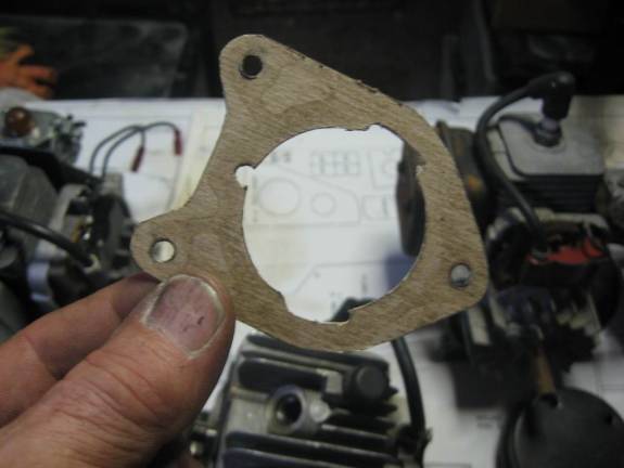
A pic of the thicker cylinder gasket I made. (use notebook cardboard, cereal boxes, file folders, etc. to make gaskets.) Harbor Freight sells a really neat hole punch kit that makes making gaskets fun. (Well, sort of….)
I don’t use any sealer on the base gasket normally, and NEVER use any sealer on the carb adapter or carb gaskets.
Put a nice film of two stroke oil on the piston, ring, and cylinder wall and put ‘er back together for the last time. (Hopefully!)
With the cylinder bolted on, a final check of the squish distance shows a perfect .020”.
This article is continued in the next post by w8ye. The reason being for the continuation is due to the limitations of the RCU editor . . .
Last edited by w8ye; 03-20-2015 at 11:01 AM.
 03-19-2015, 05:43 PM
#2


Here is the continuation of the original post by av8tor1977 . . .
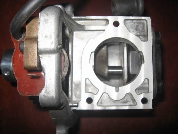
Here you can see where I used a carb gasket with a larger bore, and have ported out the intake manifold adapter to accommodate the larger carb bore. The manifold gets really, really thin at the impulse port slot, and near one of the mounting screws when you do this. On more extensive, high rpm builds, I make a dam and add manifold surface area near that one screw using JB Weld, and use a smaller head screw. Then, also using JB Weld, I fill in the impulse hole and slot, and use an external pulse port and hose to activate the fuel pump in the carb. By doing this I can port the manifold adapter hole larger than you see here. If you want a really nice handling engine, go with a carb with an 11mm venturi. If you want a bit more power, a 12.7mm venturi is the way to go, but will be a touch more finicky on adjustment and throttle up transition. (Not too badly though; that�s the size carb used on the Zenoah G-26 engines.)

Some people like to make a metal plate that they bolt to the back of the engine with countersunk screws, and then the plate bolts to the firewall to mount the engine. I don�t like adding the extra weight, and so I just use studs to mount the back plate, and then those same studs go back through the firewall with washers and nuts on them. Simple and light!

As to the muffler, you can purchase one from various sources that will be much better than the unmodified stock muffler. If not, you will definitely have to modify the stock muffler to go along with the other modifications here. It is much, much too restrictive and power robbing. What I do, is carefully undo the crimp that holds the muffler halves together. I then remove all the original baffling, screens, packing, or whatever else you might find in there. The only thing you want to leave is the two bolt spacers. These need to be there to keep the bolts from smashing the muffler when tightened. Then re-assemble the muffler and crimp it back together with the bolt spacer tubes located inside. You then need to make either one outlet with about a 5/8� diameter tube, or two outlets with at least �� diameter tubes. Braze shut any other holes in the muffler, clean it with the wire wheel on your grinder, and paint it black with engine paint. Done this way, the muffler is actually about as light as an aluminum muffler, because the aluminum is much thicker than the steel. They work fine. So�
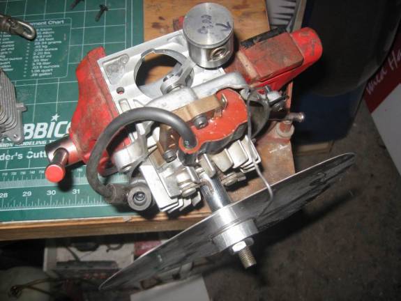
Here is the engine all assembled.


Final specs:
Squish distance = .020�
Crank pin to back plate clearance = .025�
Exhaust Open: 102 degrees ATDC
Exhaust Close: 76 degrees ABDC
Exhaust total: 154 degrees
Intake Open: 67 degrees BTDC
Intake Close: 67 degrees ATDC
Intake Total: 134 degrees
What I generally recommend is 150 to 155 degrees on the exhaust and 130 to 140 degrees on the intake for operation from around 7000 to 8000 rpms or a bit above.
For operation at 9000 and slightly above, 160 to 165 on the exhaust and about 150 on the intake seems to work well. Much more duration than 165 degrees on the exhaust is getting into tuned pipe area/timing.
If you are going for the higher rpms and the most power, definitely go with the 12.7mm venturi carb.
All done and NO paper weights created! Yes!!
This engine turned an APC 16 x 8 prop at 8400 rpms on the test stand on the first run. A bit more power and a good bit less weight could be realized by getting rid of the magneto and going to electronic ignition. This would also provide for easy hand starting and an even lower idle. It handles very nicely and is responsive throughout the rpm range. A bit more running time and a slightly larger carb would easily see 8700 rpms on the same prop, and CDI electronic ignition would help as well by eliminating the drag of the magneto flywheel, and optimizing the ignition timing. (Which should be set at 28 degrees.) This is a very nice, reliable engine. The boat guys run these engines at 10,000 rpms, so unless you run them lean or without oil, they should last forever at under 9000 rpms.
Here she is, singing away on her first run!

Source for modified Homelite 25cc piston and excellent piston rings for any engine: Frank Bowman [email protected] Phone: 505-327-0696
Here you can see where I used a carb gasket with a larger bore, and have ported out the intake manifold adapter to accommodate the larger carb bore. The manifold gets really, really thin at the impulse port slot, and near one of the mounting screws when you do this. On more extensive, high rpm builds, I make a dam and add manifold surface area near that one screw using JB Weld, and use a smaller head screw. Then, also using JB Weld, I fill in the impulse hole and slot, and use an external pulse port and hose to activate the fuel pump in the carb. By doing this I can port the manifold adapter hole larger than you see here. If you want a really nice handling engine, go with a carb with an 11mm venturi. If you want a bit more power, a 12.7mm venturi is the way to go, but will be a touch more finicky on adjustment and throttle up transition. (Not too badly though; that�s the size carb used on the Zenoah G-26 engines.)
Some people like to make a metal plate that they bolt to the back of the engine with countersunk screws, and then the plate bolts to the firewall to mount the engine. I don�t like adding the extra weight, and so I just use studs to mount the back plate, and then those same studs go back through the firewall with washers and nuts on them. Simple and light!
As to the muffler, you can purchase one from various sources that will be much better than the unmodified stock muffler. If not, you will definitely have to modify the stock muffler to go along with the other modifications here. It is much, much too restrictive and power robbing. What I do, is carefully undo the crimp that holds the muffler halves together. I then remove all the original baffling, screens, packing, or whatever else you might find in there. The only thing you want to leave is the two bolt spacers. These need to be there to keep the bolts from smashing the muffler when tightened. Then re-assemble the muffler and crimp it back together with the bolt spacer tubes located inside. You then need to make either one outlet with about a 5/8� diameter tube, or two outlets with at least �� diameter tubes. Braze shut any other holes in the muffler, clean it with the wire wheel on your grinder, and paint it black with engine paint. Done this way, the muffler is actually about as light as an aluminum muffler, because the aluminum is much thicker than the steel. They work fine. So�
Here is the engine all assembled.
Final specs:
Squish distance = .020�
Crank pin to back plate clearance = .025�
Exhaust Open: 102 degrees ATDC
Exhaust Close: 76 degrees ABDC
Exhaust total: 154 degrees
Intake Open: 67 degrees BTDC
Intake Close: 67 degrees ATDC
Intake Total: 134 degrees
What I generally recommend is 150 to 155 degrees on the exhaust and 130 to 140 degrees on the intake for operation from around 7000 to 8000 rpms or a bit above.
For operation at 9000 and slightly above, 160 to 165 on the exhaust and about 150 on the intake seems to work well. Much more duration than 165 degrees on the exhaust is getting into tuned pipe area/timing.
If you are going for the higher rpms and the most power, definitely go with the 12.7mm venturi carb.
All done and NO paper weights created! Yes!!
This engine turned an APC 16 x 8 prop at 8400 rpms on the test stand on the first run. A bit more power and a good bit less weight could be realized by getting rid of the magneto and going to electronic ignition. This would also provide for easy hand starting and an even lower idle. It handles very nicely and is responsive throughout the rpm range. A bit more running time and a slightly larger carb would easily see 8700 rpms on the same prop, and CDI electronic ignition would help as well by eliminating the drag of the magneto flywheel, and optimizing the ignition timing. (Which should be set at 28 degrees.) This is a very nice, reliable engine. The boat guys run these engines at 10,000 rpms, so unless you run them lean or without oil, they should last forever at under 9000 rpms.
Here she is, singing away on her first run!
Source for modified Homelite 25cc piston and excellent piston rings for any engine: Frank Bowman [email protected] Phone: 505-327-0696
Last edited by w8ye; 03-20-2015 at 11:06 AM.
03-20-2015, 12:41 PM
#3
Frank Bowman, at the e-mail address and/or phone number listed above, sells the special ring with a notch in it for a pinned ring setup in the Homelite 25cc that allows us to grind out that exhaust port bridge for more flow and power. He can also modify the piston and install the necessary pin for you, which is what I highly recommend as it is a rather tricky operation to install the pin. It would be easy to botch the job and ruin the piston, or worse, have the pin come out later and destroy the piston and cylinder too.
However, I have been asked to include the procedure to install a pin in the piston. So here goes:
The pin should be about the diameter of the ring groove. I use a little piece of gas welding rod. You use a drill press to drill a perfectly straight hole about .003" smaller than the size of the pin in the ring groove. You want to locate it where there are no ports in the cylinder, like in between the transfer and the exhaust port. This is critical. Then I use a bit of JB Weld on the pin, and with the piston held in a padded "V" block, very carefully drive the pin into the hole with a hammer and a small pin punch. (It's a three handed deal.) Start it straight and don't miss, or you'll ruin the ring land. Usually you size the pin to be the full depth of the ring land plus the distance of the hole you drilled, so as to be able to handle the pin and drive it in properly. But the pin has to end up being only 1/2 the depth of the ring groove. So you have to very, very carefully grind or file down the pin until it is only sticking up halfway into the ring groove. Once again, this is critical as if you don't get it right, you will either break Frank's special ring when you assemble the engine, or have a tight spot there because the pin is holding the ring up. Not good! The other thing is most people don't realize that the piston ring must seal on the bottom of the ring groove in the piston as well as against the cylinder wall. If you damage the ring land, or groove, the ring won't seal well and the engine will be down on power.
Note that the Homelite 30cc engine, which is identical to the 25cc except for the bore size, has a pinned piston and an exhaust port without a bridge from the factory. It weighs exactly the same as the 25cc, and is a better candidate for your airplane engine. As of the date of this posting, I have been seeing Homelite 30cc engines in the Ryobi brand of string trimmer, and in some of the Homelite brand handheld leaf blowers.
AV8TOR
Last edited by av8tor1977; 03-20-2015 at 12:44 PM.
03-23-2015, 05:19 PM
#4

Join Date: Oct 2004
Location: Coshocton, OH
Posts: 290
Likes: 0
Received 0 Likes
on
0 Posts
Frank Bowman, at the e-mail address and/or phone number listed above, sells the special ring with a notch in it for a pinned ring setup in the Homelite 25cc that allows us to grind out that exhaust port bridge for more flow and power. He can also modify the piston and install the necessary pin for you, which is what I highly recommend as it is a rather tricky operation to install the pin. It would be easy to botch the job and ruin the piston, or worse, have the pin come out later and destroy the piston and cylinder too.
However, I have been asked to include the procedure to install a pin in the piston. So here goes:
The pin should be about the diameter of the ring groove. I use a little piece of gas welding rod. You use a drill press to drill a perfectly straight hole about .003" smaller than the size of the pin in the ring groove. You want to locate it where there are no ports in the cylinder, like in between the transfer and the exhaust port. This is critical. Then I use a bit of JB Weld on the pin, and with the piston held in a padded "V" block, very carefully drive the pin into the hole with a hammer and a small pin punch. (It's a three handed deal.) Start it straight and don't miss, or you'll ruin the ring land. Usually you size the pin to be the full depth of the ring land plus the distance of the hole you drilled, so as to be able to handle the pin and drive it in properly. But the pin has to end up being only 1/2 the depth of the ring groove. So you have to very, very carefully grind or file down the pin until it is only sticking up halfway into the ring groove. Once again, this is critical as if you don't get it right, you will either break Frank's special ring when you assemble the engine, or have a tight spot there because the pin is holding the ring up. Not good! The other thing is most people don't realize that the piston ring must seal on the bottom of the ring groove in the piston as well as against the cylinder wall. If you damage the ring land, or groove, the ring won't seal well and the engine will be down on power.
Note that the Homelite 30cc engine, which is identical to the 25cc except for the bore size, has a pinned piston and an exhaust port without a bridge from the factory. It weighs exactly the same as the 25cc, and is a better candidate for your airplane engine. As of the date of this posting, I have been seeing Homelite 30cc engines in the Ryobi brand of string trimmer, and in some of the Homelite brand handheld leaf blowers.
AV8TOR
However, I have been asked to include the procedure to install a pin in the piston. So here goes:
The pin should be about the diameter of the ring groove. I use a little piece of gas welding rod. You use a drill press to drill a perfectly straight hole about .003" smaller than the size of the pin in the ring groove. You want to locate it where there are no ports in the cylinder, like in between the transfer and the exhaust port. This is critical. Then I use a bit of JB Weld on the pin, and with the piston held in a padded "V" block, very carefully drive the pin into the hole with a hammer and a small pin punch. (It's a three handed deal.) Start it straight and don't miss, or you'll ruin the ring land. Usually you size the pin to be the full depth of the ring land plus the distance of the hole you drilled, so as to be able to handle the pin and drive it in properly. But the pin has to end up being only 1/2 the depth of the ring groove. So you have to very, very carefully grind or file down the pin until it is only sticking up halfway into the ring groove. Once again, this is critical as if you don't get it right, you will either break Frank's special ring when you assemble the engine, or have a tight spot there because the pin is holding the ring up. Not good! The other thing is most people don't realize that the piston ring must seal on the bottom of the ring groove in the piston as well as against the cylinder wall. If you damage the ring land, or groove, the ring won't seal well and the engine will be down on power.
Note that the Homelite 30cc engine, which is identical to the 25cc except for the bore size, has a pinned piston and an exhaust port without a bridge from the factory. It weighs exactly the same as the 25cc, and is a better candidate for your airplane engine. As of the date of this posting, I have been seeing Homelite 30cc engines in the Ryobi brand of string trimmer, and in some of the Homelite brand handheld leaf blowers.
AV8TOR
03-23-2015, 09:46 PM
#5
As I mentioned in the first sentence of the posting about pinning the piston, the pin should be whatever you can find that is about the same diameter as the width of the ring groove. It is a bit tough to drill a hole in a ring groove that is larger than the diameter of the groove, and often times when you try to do so, you will break a bit and/or damage the ring groove. That's why I suggest measuring the width of the groove, and then planning to use a pin that is close to the same diameter. Do not quote me on this, but it seems as though the last time I did one, which was some time ago, I used a gas welding rod with a diameter of .063" to make the pin.
Then, since you want a press fit in the aluminum for the pin, I suggest precision measuring the pin with a micrometer, and then using a drill bit that is .003" less than the diameter of the pin for your hole in the piston. You will really need a drill press and a "V" block for the piston for doing this procedure, as the hole has to be perfect. If done by hand, it will surely not be perfectly straight nor round, and you will not be able to trust the press fit of the pin. That could be disastrous for the engine.
The depth will vary with the different pistons encountered with the various Homelite 25cc engines. In some cases, you will break right through the ring land while drilling, and of course, that is as deep as you can go. In other cases, the drill will go partly into the piston crown, and partly into the interior of the piston. Once again, that will determine your depth, as once the hole breaks through to the interior of the piston, don't bother drilling any farther. And lastly, the drill might go entirely into the piston crown, and never break through to the interior area of the piston. In that case, I would drill the hole, let's say, approximately the same depth as the depth of the ring land.
Sorry but I do not have any pics of me doing the procedure. I had figured on referring people to Frank Bowman for doing it, as it is a fairly critical operation. However, I have recently been informed that Frank is so busy making rings for customers worldwide, that he does not have the time anymore to do the pinning operation. So, proceed very carefully, and be patient while doing the procedure. As mentioned, I use a tiny bit of JB Weld on the pin when punching/pressing it in place. Just be sure to clean any excess JB Weld away before it dries. And when you grind that pin down to be only half way protruding into the ring groove, be super careful that you do not damage the ring groove while doing so.
AV8TOR
03-24-2015, 06:02 AM
#7
If you can find a file that is narrow enough, like a flat jewelers file, I would use that. If not, a cutoff/grinding disk in a Dremel tool will work, but man, be careful with that.
When installing the ring, just make sure that the notches in the gap align with the pin.
AV8TOR
When installing the ring, just make sure that the notches in the gap align with the pin.
AV8TOR
03-24-2015, 08:36 AM
#8
If you can find a file that is narrow enough, like a flat jewelers file, I would use that. If not, a cutoff/grinding disk in a Dremel tool will work, but man, be careful with that.
When installing the ring, just make sure that the notches in the gap align with the pin.
AV8TOR
When installing the ring, just make sure that the notches in the gap align with the pin.
AV8TOR
Sincerely, Richard
03-25-2015, 01:35 PM
#13
The best check is to look into the exhaust port and see what the piston and rings look like. If the piston is smooth, shiny, and a bit oily it is probably a good candidate for rebuild and hop up. If there are any signs of seizure, grooves, lots of carbon on the side of the piston, etc., it is best to "pass" on the engine.
As far as compression, what I do is squirt just a bit of a very thin oil like WD-40 into the spark plug hole. Then I block the carb wide open, and do the compression test, pulling the start rope about 4 or 5 times. 140-150 is excellent, and you'll rarely if ever see a used engine go that high. 100 psi is about the minimum to start and run well, and down at 70 they will barely run, if at all. Don't use a thick oil to do this test, such as two stroke oil or 30 weight, as it will seal the ring, worn or not, and give you a false high compression reading.
But we should always rebuild a used conversion engine to use on airplanes especially if we are going to hop them up, so the compression really doesn't matter unless you are going to run the engine as is. More important is the condition of the piston and cylinder for a rebuild with a new ring.
I was going through my engines yesterday and found a couple of Homelite 30cc engines I didn't know I had. I have to check them to see if they are good, but if anyone is interested in buying them please send me a PM.
AV8TOR
04-11-2015, 02:20 PM
#16
What I do is first align the chuck perfectly with the "V" block by chucking a bit in the drill press, and lowering the chuck while adjusting the position of the "V" block until the drill bit hits perfectly in the bottom center of the "V". I then, using a very sharp fine point punch, center punch exactly where I want to drill the hole in the piston. (Remember that this must be in a spot of the ring groove that will not align with any ports in the assembled engine!) Then, using a drill bit less than half the size of the hole I eventually want, I carefully position the piston in the "V" block aligned with the drill bit and drill the hole. Using a high speed on the drill press chuck, and very light pressure when drilling the hole helps keep it on track. Once the small guide hole is drilled, I follow up with the final size drill I want the hole to be.
To directly answer your last question, I have often chucked a pin vise into my drill press to drill very tiny holes. Just be careful, as some of the cheaper pin vises do not actually center the drill bit well in their chucks. This is not too noticeable when using the pin drill by hand, but it will really wobble when chucked into a drill press.
AV8TOR
Last edited by av8tor1977; 04-11-2015 at 02:24 PM.
04-11-2015, 04:35 PM
#17
Join Date: Oct 2004
Location: Coshocton, OH
Posts: 290
Likes: 0
Received 0 Likes
on
0 Posts
Few additional questions. What type sand paper and grit do we use to remove the squish band? Size of Pvc tube? Second, when do you record the exhaust, intake timing, soon as we see the light through the port or different?
Third, What size screw for the little hole above the exhaust? Tap?
Third, What size screw for the little hole above the exhaust? Tap?
04-12-2015, 09:13 AM
#18
Ok, for sandpaper to take out that squish band, you want something in about 36 or 80 grit and as stiff as possible. I cut mine out of a very stiff side grinder disc. Glue it securely to the end of the PVC pipe and make sure it stays straight and flat and dries well. "Goop" shoe glue from Walmart works great for things like this. I believe the size of the PVC tube is 3/4". It nicely fits into the 25cc cylinder with a slip, almost snug fit. Monitor your progress as you grind out that squish band. You may need to lean slightly harder on one side or another of the tube if it is not grinding out the squish band evenly. Use caution that you do not score the cylinder wall with the sandpaper, grit, grindings, nor the tool.
I gauge the beginning of a port opening when I get just barely begin to see a bit of light showing through a port being uncovered by the piston. Closing is the same; when the light just barely goes away, that's the closing time.
I can't remember exactly what size that hole above the muffler is, but I believe it is either an 8-32 or 10-32. I found that I didn't even need to drill the hole out; just tap it as it is already the right size. Just don't break a tap off in the hole!!. I am not where most of my engine work is done, so I don't have access to some of my stuff to refer to and give more precise answers.
Now that you all see how much is involved with "hopping an engine up", you probably understand why I don't normally take orders to do them. Too much work involved for what a person could charge. But it is a fun and satisfying thing to do as a hobby. The engine shown is not even a maximum effort/get all the power you can engine, and it was still labor intensive.
Hope that helps,
AV8TOR
04-29-2015, 06:36 PM
#20

180 is the number of degrees total exhaust opening time normally. 180 is considered fairly high, mainly for a piped motor. The bypass ports are slightly lower in the cylinder and will be something like 135 degrees total. BTDC is before top dead center. ATDC is after top dead center, and ABDC is after bottom dead center.
04-30-2015, 07:19 AM
#22
In this case, 180 does not refer to the exhaust duration. It refers to the distance between TDC and BDC; 180 degrees. Exhaust port timing is measured in degrees ATDC for the opening, and ABDC for the closing. Using the 180 in the formula I gave, results in obtaining the total exhaust duration.
(Copy and paste of post): A special note here because I know people will ask. Here’s how you find that exhaust duration:
180 – 106 = 74 degrees. 74 (from ATDC to BDC) + 74 (ABDC) = 148 total degrees the exhaust port is open. If it is easier for you, just count the total open degrees on the degree wheel.
Another copy and paste explaining exhaust total durations and effect: What I generally recommend is 150 to 155 degrees on the exhaust and 130 to 140 degrees on the intake for operation from around 7000 to 8000 rpms or a bit above.
For operation at 9000 and slightly above, 160 to 165 on the exhaust and about 150 on the intake seems to work well. Much more duration than 165 degrees on the exhaust is getting into tuned pipe area/timing.
One really should be quite familiar with engines in general and be handy with metal working and modification/fabrication skills before attempting a hop up project such as this. It is an advanced skill, and as mentioned, a mistake could be costly and frustrating .
AV8TOR
Last edited by av8tor1977; 04-30-2015 at 07:23 AM.


