


Stihl MS660 big bore conversion.


 10-14-2015, 12:14 AM
#28

Thread Starter

Join Date: Sep 2015
Location: Bellingen NSW Australia
Posts: 332
Likes: 0
Received 0 Likes
on
0 Posts
Yes, understood. The genuine part is available and is only $17. Won't break the budget. The after market open race bearings are only $8.50 each here.
10-14-2015, 05:46 AM
#30


The clutch side bearing is 17 X 40 X 14 and is a Stihl bearing Notice that it is wider than standard?
The flywheel side is a 6203 which is 17 X 40 X 12
It might not make any difference on the rear bearing - being as you are going to cut the crank off and put a plug in the hole?
The flywheel side is a 6203 which is 17 X 40 X 12
It might not make any difference on the rear bearing - being as you are going to cut the crank off and put a plug in the hole?
10-14-2015, 12:01 PM
#31
Thread Starter
Join Date: Sep 2015
Location: Bellingen NSW Australia
Posts: 332
Likes: 0
Received 0 Likes
on
0 Posts
The clutch side bearing is 17 X 40 X 14 and is a Stihl bearing Notice that it is wider than standard?
The flywheel side is a 6203 which is 17 X 40 X 12
It might not make any difference on the rear bearing - being as you are going to cut the crank off and put a plug in the hole?
The flywheel side is a 6203 which is 17 X 40 X 12
It might not make any difference on the rear bearing - being as you are going to cut the crank off and put a plug in the hole?
10-14-2015, 01:00 PM
#33
Thread Starter
Join Date: Sep 2015
Location: Bellingen NSW Australia
Posts: 332
Likes: 0
Received 0 Likes
on
0 Posts
10-15-2015, 05:08 PM
#34
Thread Starter
Join Date: Sep 2015
Location: Bellingen NSW Australia
Posts: 332
Likes: 0
Received 0 Likes
on
0 Posts
I am going to machine down the standard flywheel with the hope that it will have enough metal thickness to provide a flange to take the new extension, which I will turn up. The extension will have a mating flange with a spigot and be fixed with four axial studs. The flywheel is a kind of plastic/alloy combination; it is hard to tell if this will do the job before I start reducing it down. There is every chance I will have to start from scratch.
Can one of you experienced engine builders describe a step by step set of instructions of how to make the extension please? Any drawings or picture will help. At this stage, I can't see how it can be done without machining the taper to fit the crankshaft, then turning it around and do the other end. I have no experience in dialling in a job like this would require, but have seen it done.
Also, what alloy is suitable?
Last edited by Jim.Thompson; 10-15-2015 at 05:25 PM.
10-15-2015, 05:59 PM
#35
Thread Starter
Join Date: Sep 2015
Location: Bellingen NSW Australia
Posts: 332
Likes: 0
Received 0 Likes
on
0 Posts
For those interested in the build thread for the plane, here it is:
http://www.rcgroups.com/forums/showt...9#post32950628
http://www.rcgroups.com/forums/showt...9#post32950628
10-15-2015, 11:57 PM
#36
how i make single piece hubs: bore a pilot hole in the hub stock that is slightly smaller than the diameter of the small end of the taper. add a counterbore large enough to accept the crank nut and socket. this should have a flat bottom for the nut/washer to seat on. for my engines this is usually 19mm. make the bore about 1mm deeper than needed so you will have something to remove when facing the front of the hub later on. back end of the hub where the taper goes should also have some extra stock left. concentricity between this bore and the stock isn't important. if doing this on a mill then now is the time to add the prop screw holes in the same setup so they are concentric to the counterbore.
now chuck up a piece of round stock that is larger than your counterbore. i use 20mm ground stock in a collet but a regular 3-jaw chuck is fine as runout isn't important. turn this stock to a shrink fit with the counterbore in your hub stock. make it long enough so that you can still get in to face the front of the hub but no more than that. put a shallow couterbore in the end of your new mandrel that is slightly larger than the small diameter of the crank's taper, this is to allow whatever tool you use to cut the taper to pass through without hitting the mandrel.
mount your hub stock on the mandrel and cut the OD, both faces and the taper. go slow with the taper so you can check it against the crank. to broach the keyway grind up a very sharp tool the same thickness as the key and mount it centered with the hub. use the compound set at the same taper angle to plunge cut and wind out the cross slide a bit with each plunge until you get the depth needed. nice if you can lock the spindle but not really necessary as each cut should follow the last.
important part is to never remove the mandrel from the chuck until you are done.
6061-t6 or 2024-t4 are both fine.
10-16-2015, 11:40 AM
#38
Thread Starter
Join Date: Sep 2015
Location: Bellingen NSW Australia
Posts: 332
Likes: 0
Received 0 Likes
on
0 Posts
Thanks Zagnut. However, I have read your description maybe 10 times and cannot understand it. You describe it as "single piece hub", but it seems from my interpretation of your text there are two separate components machined. Or have I got that confused?
How is the crankshaft retaining nut fitted and accessed? There is no mention of that.
At the end of paragraph 2 in your text above, is the hub removed from the lathe chuck and then the second piece of round stock chucked up in the lathe?
Many questions arising. Maybe because I am not a machinist/fitter and turner.
10-16-2015, 03:46 PM
#39
by single piece i mean that the tapered end is integral to the hub instead of being separate like with the zenoah or conversions where the flywheel is turned down.
yes, end of second paragraph the hub is removed from the lathe or mill as concentricity is not an issue at that stage. the 19mm counterbore described here is the access for the nut that holds the hub to the crank. on commercial engines this will usually be a special nut that also includes the 10mm prop centering shaft on the opposite end. i just use the regular nut and then a plug with the centering shaft is inserted into the bore and held with set screws.
third paragraph describes the steel mandrel used to hold the hub for the rest of the machining. this is just a tool and not part of the hub.
the plug with center shaft can be seen in the attachment. the three flutes cut in the plug provide seats for the set screws without marring the outer surface. it is a very close fit in the hub, any dings and it would not be coming out again.
10-16-2015, 04:08 PM
#40
Thread Starter
Join Date: Sep 2015
Location: Bellingen NSW Australia
Posts: 332
Likes: 0
Received 0 Likes
on
0 Posts
It's beginning to become clearer, thanks for sticking with me on this.
I'm still not clear on this bit: "mount your hub stock on the mandrel and cut the OD".
Can you explain this for me please?
I'm still not clear on this bit: "mount your hub stock on the mandrel and cut the OD".
Can you explain this for me please?
10-17-2015, 07:44 AM
#41
the hub stock that you put the pilot hole and counterbore into is slid over the steel mandrel that you machined to fit and that is still chucked in the lathe. this mandrel is your work holder. a shrink fit is my preferred way and reasonably easy to do in aluminium mounted on steel. only tool needed is a toaster oven. a tight sliding fit would also be OK but would need to be secured somehow, glue or loctite would do it and either heat or some kind of solvent could be used to debond the parts when done. any perceptible slop between the mandrel and hub means the mandrel is too small and needs to be done again.
the whole idea behind this method is that it guarantees perfect concentricity without the need for any indicating or aligning. swapping a part end for end in a regular 3 jaw chuck there is no way you would come even close no matter how much time you spend indicating the part.
oh, and OD= outside diameter, ID= inside diameter
Last edited by ZAGNUT; 10-17-2015 at 07:46 AM.
10-17-2015, 09:02 AM
#42
This is the key element in Zagnut's discussion . . .
"the whole idea behind this method is that it guarantees perfect concentricity without the need for any indicating or aligning. swapping a part end for end in a regular 3 jaw chuck there is no way you would come even close no matter how much time you spend indicating the part."
"the whole idea behind this method is that it guarantees perfect concentricity without the need for any indicating or aligning. swapping a part end for end in a regular 3 jaw chuck there is no way you would come even close no matter how much time you spend indicating the part."
10-17-2015, 01:48 PM
#43
Thread Starter
Join Date: Sep 2015
Location: Bellingen NSW Australia
Posts: 332
Likes: 0
Received 0 Likes
on
0 Posts
....................................
the whole idea behind this method is that it guarantees perfect concentricity without the need for any indicating or aligning. swapping a part end for end in a regular 3 jaw chuck there is no way you would come even close no matter how much time you spend indicating the part.
oh, and OD= outside diameter, ID= inside diameter
1. How is the shrink fitted hub removed from the steel mandrel after the hub is finished?
2. Is the second part of the this "one part hub" ( very confusing....... this is one of the things that threw me from the start), by that I mean the centreing plug with pin to go through the prop, machined separately and shrink fitted into the hub?
3. How can the hub be removed if required later? There are no provisions visible to take the jaws of a puller.
10-17-2015, 02:16 PM
#44
the plug with center shaft is just a very close slip fit and held with the three set screws. needs to be easily removable to get the hub off the engine.
for hub removal i have a thick prop washer made of steel with the center hole threaded. remove center plug and nut from hub, mount the special washer with all six prop screws tightened down, long bolt with pointed tip goes in the center and is tightened against the crank nose. exact same concept as a regular puller.....you could make the hub compatible with a regular puller as well.
to remove the hub from mandrel just toss the whole assembly in the toaster and if needed use a regular puller or press it out in a drill press while still hot. shouldn't need a lot of force. if you don't want to remove the mandrel from the chuck then a heat gun will work.
Last edited by ZAGNUT; 10-17-2015 at 02:18 PM.
10-17-2015, 02:47 PM
#45
Thread Starter
Join Date: Sep 2015
Location: Bellingen NSW Australia
Posts: 332
Likes: 0
Received 0 Likes
on
0 Posts
I've got it! Very nice method. I'm already tempted to just go for doing it this way rather than making a mandrel to mount the old flywheel on and machining that down etc.
There is time to think about it now, I won't be doing it for at least a month or two.
Thanks again.
Two more questions:
1. How are the six prop retaining screws drilled while the hub is still in the lathe chuck?
2 Should I make up a drilling guide first? Out of some thick steel plate or round stock?
Last edited by Jim.Thompson; 10-17-2015 at 08:45 PM.
10-18-2015, 03:24 AM
#46
Member
Join Date: Feb 2014
Posts: 87
Likes: 0
Received 0 Likes
on
0 Posts
I posted a Video https://www.youtube.com/watch?v=qqlexLHi3dEon You Tube on how to make a Prop Adapter, Type in Pouland Prop Adapter.
Larry
Larry
10-18-2015, 07:38 AM
#47
in the lathe you would need some way to index the spindle and live tooling to drill and tap for the prop screws. that's why i prefer to do the prop screws on the mill in the same setup i do the counterbore for the mandrel...concentric without the need to even check it. you could get by with a drill jig if it had hole sizes for both drilling and tapping but then you are going to need one of the above mentioned methods to make the jig.
edit: one of the commercially available jigs would work fine after bushing the holes down with brass tubing or similar. would be a good idea to drill and tap on a drill press and not free hand. the 10mm center shaft is responsible for centering the prop so no worries if your bolt circle is a hair off.
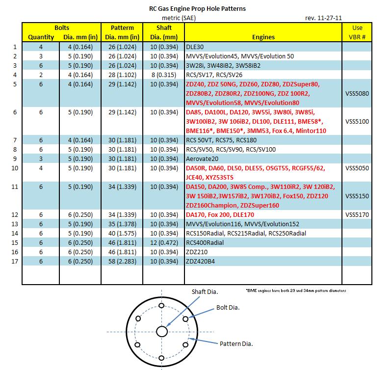
hobbyking probably has a jig for cheap. six M5 screws on a 29mm circle would be the default choice for an engine this size.
edit: one of the commercially available jigs would work fine after bushing the holes down with brass tubing or similar. would be a good idea to drill and tap on a drill press and not free hand. the 10mm center shaft is responsible for centering the prop so no worries if your bolt circle is a hair off.
hobbyking probably has a jig for cheap. six M5 screws on a 29mm circle would be the default choice for an engine this size.
Last edited by ZAGNUT; 10-18-2015 at 10:38 AM.
10-18-2015, 12:23 PM
#48
Thread Starter
Join Date: Sep 2015
Location: Bellingen NSW Australia
Posts: 332
Likes: 0
Received 0 Likes
on
0 Posts
Thanks again Zagnut.
I will look at the HobbyKing offering. However, I just might be able to get an engineer pal to make me up a drill guide. Unless of course, I figure out how to do it without a mill.
I will look at the HobbyKing offering. However, I just might be able to get an engineer pal to make me up a drill guide. Unless of course, I figure out how to do it without a mill.
10-20-2015, 01:08 PM
#49
If using a aftermarket cylinder and piston, do not just assume everything fits perfect as you might with genuine Stihl parts.
Observe the piston skirt to crank counter weight clearance as well as taking a squish measurement between the piston and edge of the combustion chamber.
Clean off all burrs and compare the new parts very closely with the old parts
Stick both pistons on one wrist pin and compare deck heights as well as skirt lengths.

