


Mk-16
 02-12-2015, 05:12 PM
#1

Thread Starter
My Feedback: (2)
Join Date: Feb 2002
Location: Hervey Bay Queensland, AUSTRALIA
Posts: 2,995
Likes: 0
Received 0 Likes
on
0 Posts
What is known about these little fellows?
The example below is engraved with serial no. B719. It is castor/cosmolene locked, has no washer marks, and appears to be un-run.
Overall build quality appears to be higher than for the later MK-17.
The example below is engraved with serial no. B719. It is castor/cosmolene locked, has no washer marks, and appears to be un-run.
Overall build quality appears to be higher than for the later MK-17.
 02-13-2015, 06:57 AM
#2

Not too much info about it, the Mk17 seems to have been derived from it.
http://modelenginenews.org/cardfile/mk17.html
http://sceptreflight.net/Model%20Eng...sts/MK-17.html
http://www.rojobcn.com/technic/avion/mk16.htm
http://youtu.be/tfeeHTmoaD8
http://modelenginenews.org/cardfile/mk17.html
http://sceptreflight.net/Model%20Eng...sts/MK-17.html
http://www.rojobcn.com/technic/avion/mk16.htm
http://youtu.be/tfeeHTmoaD8
Last edited by coriolan; 02-13-2015 at 07:06 AM.
02-13-2015, 11:23 AM
#3


Yes, unfortunately, due to the cold war at the time, there just isn't much if any information about the engines out of Russia. Many of the engine makers at the time, for what ever reason, never identified themselves either. There might have been good reason for that too. But I think you are correct in that the MK-16 was the predecessor to the MK-17. I think the MK-16's likely were made in small numbers at several different locations. But when the government took a interest they caused production to expand and the more improved MK-17 came about then. The MK-17 looks to have been made at just about every factory in Russia at the time.
02-13-2015, 11:49 PM
#4
Senior Member
Join Date: Oct 2009
Location: SydneyNew South wales, AUSTRALIA
Posts: 1,346
Likes: 0
Received 4 Likes
on
4 Posts
02-14-2015, 08:16 PM
#5
Thread Starter
My Feedback: (2)
Join Date: Feb 2002
Location: Hervey Bay Queensland, AUSTRALIA
Posts: 2,995
Likes: 0
Received 0 Likes
on
0 Posts
There appears to have been some evolution to the MK-16
First image shows an early sand cast model with separate front housing.
Second and third images, later unitary 'black' and 'grey' case versions, with MK-17 type NVA's.
At a guess I'd say mine is an early unitary case example. It runs well but is very tight, and will not yet hold peak without going over.
https://www.youtube.com/watch?v=Ge0V...CHC8Gs5NaDm-zA
Last edited by fiery; 02-15-2015 at 04:56 PM.
02-14-2015, 08:28 PM
#6
Thread Starter
My Feedback: (2)
Join Date: Feb 2002
Location: Hervey Bay Queensland, AUSTRALIA
Posts: 2,995
Likes: 0
Received 0 Likes
on
0 Posts
Some shots from preparation before running. It is unlikely the engine had never been opened since it left the works.
General construction quality is good. The only let down are the back plate screws, which are made from 'butter steel', and will be replaced.
Inside it was clean apart from gummy residue. No swarf at all. The brown paper back plate gasket disintegrated upon separation of the back plate from the case. I made up a new gasket from 0,4 m.m. Klinger Oilstat gasket paper. The fuel inlet banjo was sealed on each face with thin black leather washers. After 50 plus years these also disintegrated. They were replaced with red fibre washers which will hold up in use and seal better.
The third photograph shows one of the two (!) grooves in the piston above the gudgeon pin. The grooves are quite wide - approx. 0,8 mm as measured by my visual vernier - and deep; as if for a ring.
The piston is of course a lapped fit. A nice job it is too. Lots of excess weight removed and with quite a thin skirt by the standards of the day. Plenty of support for the gudgeon pin. It holds compression well hot or cold. My guess is that the grooves were intended to reduce friction. Happy to be advised otherwise.
General construction quality is good. The only let down are the back plate screws, which are made from 'butter steel', and will be replaced.
Inside it was clean apart from gummy residue. No swarf at all. The brown paper back plate gasket disintegrated upon separation of the back plate from the case. I made up a new gasket from 0,4 m.m. Klinger Oilstat gasket paper. The fuel inlet banjo was sealed on each face with thin black leather washers. After 50 plus years these also disintegrated. They were replaced with red fibre washers which will hold up in use and seal better.
The third photograph shows one of the two (!) grooves in the piston above the gudgeon pin. The grooves are quite wide - approx. 0,8 mm as measured by my visual vernier
- and deep; as if for a ring.The piston is of course a lapped fit. A nice job it is too. Lots of excess weight removed and with quite a thin skirt by the standards of the day. Plenty of support for the gudgeon pin. It holds compression well hot or cold. My guess is that the grooves were intended to reduce friction. Happy to be advised otherwise.
Last edited by fiery; 02-14-2015 at 10:22 PM.
02-18-2015, 11:53 AM
#7
The engine is looking pretty good. It probably wasn't made at numerous locations and different factories like the MK-17 was. So maybe the quality is better.
I think what was cool about these rear intake rotary valve engines was how some of them got converted to four stroke engines. It sort of made it easy to convert them.
Granted you needed a new cylinder sleeve, head, and backplate as well as valves and a gear train and cams. But it was pretty cool to see some that were made into four stroke engines.
02-19-2015, 05:43 PM
#9
Join Date: Oct 2005
Location: ACTAustralia, AUSTRALIA
Posts: 393
Likes: 0
Received 0 Likes
on
0 Posts
Yo Fiery
Your Pictures had a fatal attraction ,
I will have to get out the Diesel Dan on the weekend
See if I can find a small patch of grass , now where did that Mercury Picador get to
Your Pictures had a fatal attraction ,
I will have to get out the Diesel Dan on the weekend
See if I can find a small patch of grass , now where did that Mercury Picador get to
02-19-2015, 05:49 PM
#10
Thread Starter
My Feedback: (2)
Join Date: Feb 2002
Location: Hervey Bay Queensland, AUSTRALIA
Posts: 2,995
Likes: 0
Received 0 Likes
on
0 Posts
Hello Howard.
In the MEN web article on the MK-17, the author states that:
"from Peter Chinn's column in the February 1976 issue [of Aeromodeller] [2]. ... Peter notes that the Mk 17 is a development of the Mk 16K, and that the latter was designed by one V Petukhov, "..as long ago..." as 1956 ..."
In the MEN web article on the MK-17, the author states that:
"from Peter Chinn's column in the February 1976 issue [of Aeromodeller] [2]. ... Peter notes that the Mk 17 is a development of the Mk 16K, and that the latter was designed by one V Petukhov, "..as long ago..." as 1956 ..."
Last edited by fiery; 03-15-2015 at 09:31 PM.
02-19-2015, 06:49 PM
#12
02-21-2015, 04:27 AM
#13
I believe the MK-16 dates back to around 1958 and the first engines had a 4-screw front housing and gold muff. The second version had a unit construction one piece case in black, with gold muff.
The gold muffs were smaller in diameter than the later MK-17 red muffs.
The gold muffs were smaller in diameter than the later MK-17 red muffs.
02-22-2015, 01:37 PM
#15
Join Date: Oct 2005
Location: ACTAustralia, AUSTRALIA
Posts: 393
Likes: 0
Received 0 Likes
on
0 Posts
The penultimate motor for the Picador
Except for the spinner , mine always vibrate off
and you cant flick it either , and also the tank is problematic behind the intake protrusion
Except for the spinner , mine always vibrate off
and you cant flick it either , and also the tank is problematic behind the intake protrusion
02-22-2015, 06:09 PM
#17
Join Date: Oct 2005
Location: ACTAustralia, AUSTRALIA
Posts: 393
Likes: 0
Received 0 Likes
on
0 Posts
Fiery
Thanks for the fine detail pictures , makes me feel like I own a Mk16 , or a Mk17 ,
its the penultimate 1.5 cc Diesel , like running a Team race engine in your ship , and easy to handle too
Thanks for the fine detail pictures , makes me feel like I own a Mk16 , or a Mk17 ,
its the penultimate 1.5 cc Diesel , like running a Team race engine in your ship , and easy to handle too
02-23-2015, 12:02 AM
#19
Thread Starter
My Feedback: (2)
Join Date: Feb 2002
Location: Hervey Bay Queensland, AUSTRALIA
Posts: 2,995
Likes: 0
Received 0 Likes
on
0 Posts
G'day there!
Its a really nice little engine. Looks to be made by persons skilled in knowing how to fit a diesel model engine. It is much better than some Soviet era products. By the standards of the day its specification as a twin ball raced 1/2 A [UK class] sport diesel was almost unheard of. It would blow my ED Hornet into the weeds on performance and finish.
It hand starts easily on a choke prime. Hence, no 'bites' to my flicking fingers. Its P/L set up is near perfect. Machining and finish of working parts is much 'nicer' than my later MK-17 1.48 cc or MARZ 2.5 cc; which are very much 'consumer' spec products. The setting of float on this MK-16's disc rotor valve pin is spot-on, and the rotor itself concentric.
I may need to reduce or eliminate DII in my fuel for it. This little black work horse appears not to like being fed any exotic additive.
Last edited by fiery; 02-23-2015 at 12:08 AM.
02-23-2015, 01:45 AM
#20
The MK-17 was also available as a glo engine. I've never run this one but hear it is nowhere near the diesel version for power output.
I don't know if the MK-16 was ever done as a glo.
I don't know if the MK-16 was ever done as a glo.
02-26-2015, 08:53 AM
#21
Member
Join Date: Oct 2014
Posts: 46
Likes: 0
Received 0 Likes
on
0 Posts
This looks like a self-made conversion. As far as I know from different russian sources, MK16 and MK17 were produced only as diesel engines for technical sections for children and students, supported by goverment of the USSR.
There is very detail description of some soviet engines, including MK16 is in this book (it's in Russian, 1973)
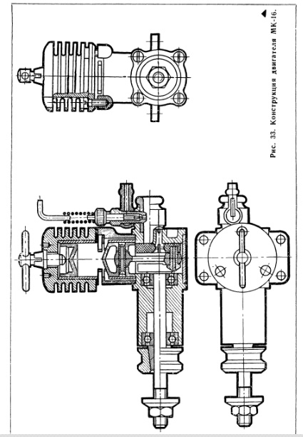
Some of pictures of MK16 from book
http://avia-master.ucoz.com/load/0-0-0-53-20
Ok, here is draft translation (sorry for mistakes, English is not my native language).
=======================================
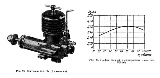
Micro engine MK-16 has the smallest working volume of cylinder among all soviet engines and the volume is 1.48cc. It was designed by V.I.Petukhov, the oldest soviet model aircraft builder, master of sports, champion of the USSR. MK-16 is diesel engine, it is simple in operation. It is very popular among experienced model builders and beginners as well. Usually it is used on a control line trainers, free flight models and control line aircraft scale models.
The design of the engine is relatively simple. It consists of: crank case, crank case front part, backplate with rotary valve, cylinder liner, piston and conrod, counter piston, cooling head, needle valve assembly, and crankshaft
The case is made with chill casting of aluminium AL4 (USA analogue Aluminium 354.0). The case has screw holes for fixing front part, backplate and cooling head. The thread of screws is M2.5x0.35
Bypass ports formed between walls of crank case and cylinder liner. The expulsion of cylinder is fountain type
Backplate is made with chill casting of aluminium AL4. Backplate has a ventury pipe in which a needle valve-assembly inserted. On the inner side of backplate a valve rotates, made of composite epoxy material. The latest engines were produced with valve made of aluminium D16T (Al 2024). The valve rotates on a steel pin.
Steel cylinder liner has three exhaust ports and three bypass ports, made with disc cutter. Bypass ports are made under cylinder pad. It is aligned on outer diameter of pad. The inner surface of cylinder liner is grinded. The surface finish is <10.
The piston group consists of piston, wrist pin and conrod. Piston made of cast iron; the top of piston is conical for efficiency of expulsion and hardness. The surface of piston has three oiling grooves. The hole for wrist pin is perpendicular to axis of piston. Wrist pin diameter is 3 mm and it's made of steel. It doesn't have hole for reducing weight. Conrod is stamped aluminium D16T (Al 2024), it has small grooves on the tips for oiling.
Counter piston made of cast iron SCH21-40 (antifriction Gray Cast Iron). The bottom of counter piston is conical as well. Cone angle matches piston and it is 5 Degrees.
Cooling head made of D16T aluminium (Al 2024). It has six cooling fins. It is mounted on a crank case with three screws M2.5. The screw holes in the cooling fins clear the screw heads all the way down to the last, thick fin, 2.5 mm. On the top of cooling head a collet bushing is screwed in. It prevents counter piston screw from wandering. Counter piston screw has M4 thread.
Steel crankshaft is heat treated. The diameter of crankpin is 3.5mm
Needle valve is turnable. Needle connected with handle via soldered spring, which protects needle from damage caused by forces during engine tuning.
Specifications of MK16:
Volume: 1.48 cc
Bore: 12.85mm
Stroke: 11.4mm
Dimension: 0.888
Compression: 10-18
Max output power: 200 Watts (0.147 hp)
Max RPM: 15000
Ignition: Compression of fuel
Liter power: 135 hp/l
Mass: 0.117 kg
Power density: 0.585 kg/hp
Fuel: Kerosine - 34%, Diethyl ether 34%, Castor oil 29%, Isopropyl nitrite(Amyl nitrite) 3%
===================================
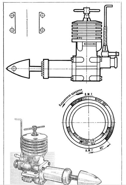
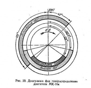
The other book is Model aircraft engines, 1958.
Has some additional info, including performance chart (hp / RPM) and timing diagram
There is very detail description of some soviet engines, including MK16 is in this book (it's in Russian, 1973)
Some of pictures of MK16 from book
http://avia-master.ucoz.com/load/0-0-0-53-20
Ok, here is draft translation (sorry for mistakes, English is not my native language).
=======================================
Micro engine MK-16 has the smallest working volume of cylinder among all soviet engines and the volume is 1.48cc. It was designed by V.I.Petukhov, the oldest soviet model aircraft builder, master of sports, champion of the USSR. MK-16 is diesel engine, it is simple in operation. It is very popular among experienced model builders and beginners as well. Usually it is used on a control line trainers, free flight models and control line aircraft scale models.
The design of the engine is relatively simple. It consists of: crank case, crank case front part, backplate with rotary valve, cylinder liner, piston and conrod, counter piston, cooling head, needle valve assembly, and crankshaft
The case is made with chill casting of aluminium AL4 (USA analogue Aluminium 354.0). The case has screw holes for fixing front part, backplate and cooling head. The thread of screws is M2.5x0.35
Bypass ports formed between walls of crank case and cylinder liner. The expulsion of cylinder is fountain type
Backplate is made with chill casting of aluminium AL4. Backplate has a ventury pipe in which a needle valve-assembly inserted. On the inner side of backplate a valve rotates, made of composite epoxy material. The latest engines were produced with valve made of aluminium D16T (Al 2024). The valve rotates on a steel pin.
Steel cylinder liner has three exhaust ports and three bypass ports, made with disc cutter. Bypass ports are made under cylinder pad. It is aligned on outer diameter of pad. The inner surface of cylinder liner is grinded. The surface finish is <10.
The piston group consists of piston, wrist pin and conrod. Piston made of cast iron; the top of piston is conical for efficiency of expulsion and hardness. The surface of piston has three oiling grooves. The hole for wrist pin is perpendicular to axis of piston. Wrist pin diameter is 3 mm and it's made of steel. It doesn't have hole for reducing weight. Conrod is stamped aluminium D16T (Al 2024), it has small grooves on the tips for oiling.
Counter piston made of cast iron SCH21-40 (antifriction Gray Cast Iron). The bottom of counter piston is conical as well. Cone angle matches piston and it is 5 Degrees.
Cooling head made of D16T aluminium (Al 2024). It has six cooling fins. It is mounted on a crank case with three screws M2.5. The screw holes in the cooling fins clear the screw heads all the way down to the last, thick fin, 2.5 mm. On the top of cooling head a collet bushing is screwed in. It prevents counter piston screw from wandering. Counter piston screw has M4 thread.
Steel crankshaft is heat treated. The diameter of crankpin is 3.5mm
Needle valve is turnable. Needle connected with handle via soldered spring, which protects needle from damage caused by forces during engine tuning.
Specifications of MK16:
Volume: 1.48 cc
Bore: 12.85mm
Stroke: 11.4mm
Dimension: 0.888
Compression: 10-18
Max output power: 200 Watts (0.147 hp)
Max RPM: 15000
Ignition: Compression of fuel
Liter power: 135 hp/l
Mass: 0.117 kg
Power density: 0.585 kg/hp
Fuel: Kerosine - 34%, Diethyl ether 34%, Castor oil 29%, Isopropyl nitrite(Amyl nitrite) 3%
===================================
The other book is Model aircraft engines, 1958.
Has some additional info, including performance chart (hp / RPM) and timing diagram
Last edited by vsv123; 02-26-2015 at 11:38 AM.
02-26-2015, 05:32 PM
#22
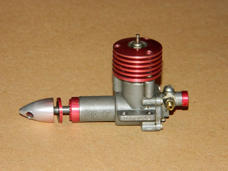
vsv123 Here's the story on the MK-17 glo. I got this engine from Stu Richmond who made several trips to Europe and he assured me this was a factory engine and there were more than just this one. Stu explained how these engines were built in schools and could vary in quality, depending on which school.
As far as Russians not using glo engines they were quite active in FAI speed and FF competitions in the 50's, 60's and later. They made many .15 glo engines; usually copies of various Supertigre .15's and later on they copied the Rossi .15. A few I can recall were made by Uckam, Vip, Kometa and the Russian Meteor. Stu showed me several Rossi copies but some had no names on the case. They did look extremely well finished.
As far as Russians not using glo engines they were quite active in FAI speed and FF competitions in the 50's, 60's and later. They made many .15 glo engines; usually copies of various Supertigre .15's and later on they copied the Rossi .15. A few I can recall were made by Uckam, Vip, Kometa and the Russian Meteor. Stu showed me several Rossi copies but some had no names on the case. They did look extremely well finished.
Last edited by Dan Vincent; 02-26-2015 at 06:08 PM.
02-26-2015, 09:33 PM
#23
Member
Join Date: Oct 2014
Posts: 46
Likes: 0
Received 0 Likes
on
0 Posts
Well may be your buddy knows what russians don't know.
But as far as soviet people know MK-17 is purely diesel engine (at least in mass production). There were convesions of that engine to glow. And many articles in magazines how to convert it.
To convert MK-17 to glow usually you have to do some major modifications, including increasing sub-induction ports, replacing weak ball bearing with stronger one, and replacing counter piston or cooling head of course. Glow conversion runs at 23500 RPM with 6.4x3 prop
http://www.rcpilot.h12.ru/engine01.html
http://yoline.3dn.ru/index/0-89
http://modelist-konstruktor.com/v_mi...nogo--kalilnyj
Last edited by vsv123; 02-26-2015 at 09:59 PM.
02-27-2015, 04:04 AM
#24
My friend, Stu Richmond, was a writer for both RC Modeler and Model Builder magazines and a noted engine collector. He knew a lot of the European engine manufactures and I took his word that this was a genuine factory engine. It will be interesting to see if more people weigh in on this thread.
