


Sailplane Wing Design Round II
 05-28-2012, 08:43 PM
#1

Thread Starter

Join Date: Feb 2012
Location: Fairfield, CT
Posts: 416
Likes: 0
Received 0 Likes
on
0 Posts
Hey folks,
This is a continuation of my Scratch Designed/Built Sailplane build log. My design flew beautifully but...

...unfortunately my wing could use a rethink. Basically it folded in half mid-flight on the fourth or fifth flight...
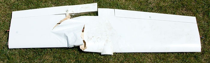
The wing was of built-up balsa & spruce construction with carbon fiber reinforcing here & there...
Thankfully the damage was limited to the wing, not sure how the fuselage survived...

So my plan is to design & build a new stronger wing. This thread will document that process.
So to get started here's a fun YouTube video featuring the old wing...
YouTube Video - Wing Failure
I'll post details about my new design shortly.
This is a continuation of my Scratch Designed/Built Sailplane build log. My design flew beautifully but...
...unfortunately my wing could use a rethink. Basically it folded in half mid-flight on the fourth or fifth flight...
The wing was of built-up balsa & spruce construction with carbon fiber reinforcing here & there...
Thankfully the damage was limited to the wing, not sure how the fuselage survived...
So my plan is to design & build a new stronger wing. This thread will document that process.
So to get started here's a fun YouTube video featuring the old wing...
YouTube Video - Wing Failure
I'll post details about my new design shortly.
 05-28-2012, 09:31 PM
#2
Senior Member
My Feedback: (2)
Join Date: May 2005
Location: Tacoma, WA WA
Posts: 353
Likes: 0
Received 0 Likes
on
0 Posts
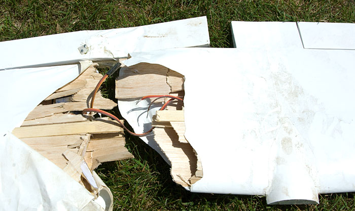
Just a quick question....is there any shear webbing between the upper and lower spars in the wing?
Unable to tell in the pictures.
Nice looking build.
Unable to tell in the pictures.
Nice looking build.
05-28-2012, 10:26 PM
#3
Thread Starter
Join Date: Feb 2012
Location: Fairfield, CT
Posts: 416
Likes: 0
Received 0 Likes
on
0 Posts
Yeap there was sheer webbing, the video shows more about the design.
I'll have some design ideas for the new wing posted soon, will give you folks a chance to tell me if I'm going in the right direction.
I'll have some design ideas for the new wing posted soon, will give you folks a chance to tell me if I'm going in the right direction.
05-29-2012, 10:48 AM
#4
Thread Starter
Join Date: Feb 2012
Location: Fairfield, CT
Posts: 416
Likes: 0
Received 0 Likes
on
0 Posts
Just so we're all on the same page, here's a few amazing articles about shear loads, spars & wing design...
Shear Loads (look at pages 20 - 21)
http://www.rcsoaringdigest.com/pdfs/...SD-2005-04.pdf
http://www.rcsoaringdigest.com/pdfs/...SD-2005-05.pdf
Compression Load at Spar or Joiner Bend (look at pages 20 - 21)
http://www.rcsoaringdigest.com/pdfs/...SD-2005-06.pdf
I found those in this very informative thread, well worth a read too...
http://www.rcgroups.com/forums/showt...00#post6164407
That's just some of what I've been reading recently. Based on my new found understanding of wing spar science I'll have a few nifty design concepts posted shortly.
05-29-2012, 12:41 PM
#5
Member
I'm sorry - and amazed - to hear this. If it's any consolation, this is even more great education for us newbies.
Looking forward to the new build thread.
Looking forward to the new build thread.
05-29-2012, 05:14 PM
#6
Thread Starter
Join Date: Feb 2012
Location: Fairfield, CT
Posts: 416
Likes: 0
Received 0 Likes
on
0 Posts
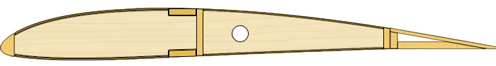
The Old Wing
The New Wing
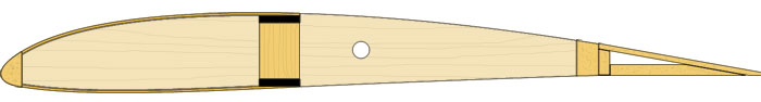
Okay so the obvious difference here is the 12mm x 2mm CF spar caps, no more wimpy spruce. After looking at a load of shear web options I've chosen to go with full spar width, vertical gain, balsa shear webbing. The CF & webbing will be epoxied together & then wrapped with Kevlar ribbon (not shown). That should produce an exceedingly strong spar.
I've eliminated the sheeting aft of the spar as I don't think its necessary, will save some weight there. Will probably fully sheet the first few bays around the center though. Speaking of the sheeting, it now overlaps the spar caps instead of butting up to them, should provide a much larger bonding surface. The holes in the ribs are for the servo wires. Lastly I doubled up the thickness of the TE material that the flaps/ailerons hinge against. The old 1/8" TE scolloped after I shrank the covering.
I'm looking into wing joinery options, have a couple of ideas in mind. Anyway that's the plan for now. Questions or suggestions? Please fire away.
The New Wing
Okay so the obvious difference here is the 12mm x 2mm CF spar caps, no more wimpy spruce. After looking at a load of shear web options I've chosen to go with full spar width, vertical gain, balsa shear webbing. The CF & webbing will be epoxied together & then wrapped with Kevlar ribbon (not shown). That should produce an exceedingly strong spar.
I've eliminated the sheeting aft of the spar as I don't think its necessary, will save some weight there. Will probably fully sheet the first few bays around the center though. Speaking of the sheeting, it now overlaps the spar caps instead of butting up to them, should provide a much larger bonding surface. The holes in the ribs are for the servo wires. Lastly I doubled up the thickness of the TE material that the flaps/ailerons hinge against. The old 1/8" TE scolloped after I shrank the covering.
I'm looking into wing joinery options, have a couple of ideas in mind. Anyway that's the plan for now. Questions or suggestions? Please fire away.
05-29-2012, 05:30 PM
#7
Senior Member
Join Date: Jan 2011
Location: Cody,
WY
Posts: 294
Likes: 0
Received 0 Likes
on
0 Posts
If you wrap the spar with bias light glass, rather than the kevlar wrap, you don't need to use vertical grain balsa. You can just use horizontal grain. This will save you some time and weight and make the dimensions of the final spar more predictable. You can mist the spar with Super 77, lay it on some smoothed out 2 ounce fiberglass and roll the spar so no wrinkles are present. Then brush on the laminating resin. It's important that the fiber oreintation of the glass be at 45* to the length of the spar. Another option is to find some light braided fiberglass sock/tubing. You can slide it over the spar, stretch it tight, and then saturate.
05-29-2012, 06:35 PM
#8
Thread Starter
Join Date: Feb 2012
Location: Fairfield, CT
Posts: 416
Likes: 0
Received 0 Likes
on
0 Posts
That'd be an option if I were planning to use split ribs butt joined to the front & rear of the spar but I'm probably not going that route. Instead I'll be using full ribs mounted between the shear webbing. That sorta rules out any sock or tubing technieques, also makes glassing a pain in the butt. Here's a photo I stole of a BubbleDancer's spar wrapped in Kevlar, using full width shear webbing...
Looks like either technieque will produce a good strong wing, for whatever reasons I like this aproach *shrug*. Thanks for the suggestions, will mull them around some, still keeping my options open.
Looks like either technieque will produce a good strong wing, for whatever reasons I like this aproach *shrug*. Thanks for the suggestions, will mull them around some, still keeping my options open.
05-29-2012, 06:50 PM
#9


Join Date: Oct 2002
Location: Chilliwack, BC, CANADA
Posts: 12,425
Likes: 0
Received 22 Likes
on
19 Posts
IMHO wrapping the spar like that would be a lot more trouble and a lot more messy than simply making up a jig and cutting out the proper vertical grain webbing.
Nodd, the width of the spruce you used should have been more than enough to hold the flight loads. So the failure mode was something else. Two possible causes that come to mind are;
[ul][*] The face joints of the webbing failed because you used too light a grade of balsa in the higher stress area near the center of the wing. For this area the webbing should have been very hard balsa or even 1/32 plywood. And to gain more joint area I'd have used the vertical webs both front and back. By putting only one piece on the back of that wide a spruce spar the failure where the upper spar wants to collapse inward to the lower spar could easily have started along the front where it was unsupported. And when it started to twist the forces could have split apart the webbing glue joint and then total collapse followed very fast.[*] The spruce used for the spar may have a high angle grain runout in that area I can't tell from the splinters in the failure area.
[/ul]
Consider this. You put the carbon fiber over the area of the spars at the center joint where they had the benefit of plywood joiners as their "webbing". And, I'd have to go back and check the other thread, likely you put plywood braces both front and back?
On the wing you broke over your knee examine the webbing to see if you can get a better idea of what part failed. I'm pretty sure it was so easy to break due to the nature of the balsa webbing or the glue lines. Couple that with a rather wide C shaped spar instead of a front and back webbing box spar and I can see it breaking that easily.
Anyhow, going with the carbon top and bottom caps with full width vertical webbing a la Mark Drela's designs will certainly do the trick. Just keep in mind that you still want to bridge the center joint with long fibers in a way similar to the carbon caps you used in this first wing.
At least you don't need to do new tip panels. Even with the weaker C shaped spars and webbing the loads out on the tips are a lot lighter.
05-29-2012, 07:13 PM
#10
Thread Starter
Join Date: Feb 2012
Location: Fairfield, CT
Posts: 416
Likes: 0
Received 0 Likes
on
0 Posts
Yeah I'm leaning towards inadiquate gluing of my shear webbing as a possible cause for the first wing's demize. I dimmly recall "spot welding" the webbing in place with thin CA. Now that I have a better understanding of what the webbing actually does I realize not gluing it in place completly along each edge was a big no no. I also know what you mean about the C shaped spar. Combined with my "gappy" butt joined sheeting, the front edge of the spar had little if no support. Yes you're correct, some areas of the spar enjoyed webbing both front & rear but not the area that failed. I can't coment on the quality of the spruce as I've already tossed the old wing.
Unfortunatly my wing rods which were glued into the outer wing pannels all fractured on impact. Faced with major surgery to replace them & a doubtfull spar I chose to toss the entire wing, outer sections included. Probably for the best.
Anyway this has been a good, if somewhat painful, learning experiance. Combined with all the great advice I'm getting, my future wings will be far stronger because of it.
05-29-2012, 09:37 PM
#11
Junior Member
My Feedback: (1)
Join Date: May 2011
Location: waukegan,
IL
Posts: 21
Likes: 0
Received 0 Likes
on
0 Posts
what would you want for one of those with the new wing? im not very good with tools and would buy one from you.
that is a beautiful sailplane.

that is a beautiful sailplane.
05-30-2012, 03:12 AM
#12
Senior Member
Just a suggestion.
You mentioned the outer wing rods fractured. That doesn't show in the pictures so that might be why we've not been talking about anything but what looks broken in the pictures. They actually were the instruments of destruction that failed the center section. Look at where your fracture line zig-zags in the pictures. The center section failure on that side is basically where those two rods seem to end inside that side. They aided the major failure and still failed, possibly as the wing folded and got some extra aero forces thrown at their joint. They probably did go on impact, but that makes you wonder what they'd do if it caught a wing on landing.
I'd think about increasing the diameter of the primary rod one step up. No need to increase the smaller aft rod.
If you've not done that area of the center section yet, you might also consider combining the rod holding tubes with the main spar out in that area. Combining structures often allows you to make each part of the combination lighter.
05-30-2012, 07:37 AM
#13
Thread Starter
Join Date: Feb 2012
Location: Fairfield, CT
Posts: 416
Likes: 0
Received 0 Likes
on
0 Posts
That's an interesting theory but although I said the wing rods "fractured", a better description would be, that they developed small cracks. The outer panels remained firmly attached to the wing even after impact. It was only when I removed them did I notice they'd been damaged. They were still quite rigid but not something I'd trust to reuse.
One of the reasons I went with rubber bands to secure the wing was to limit damage during a cartwheel landing. I'm confident the old rods would have been fine under normal use/abuse. Going straight in from a thousand feet, no I didn't plan for that LOL. Nevertheless I agree, more substantial rods would be good.
One of the reasons I went with rubber bands to secure the wing was to limit damage during a cartwheel landing. I'm confident the old rods would have been fine under normal use/abuse. Going straight in from a thousand feet, no I didn't plan for that LOL. Nevertheless I agree, more substantial rods would be good.
05-30-2012, 07:42 AM
#14
Thread Starter
Join Date: Feb 2012
Location: Fairfield, CT
Posts: 416
Likes: 0
Received 0 Likes
on
0 Posts
ORIGINAL: jonnynoz
what would you want for one of those with the new wing? im not very good with tools and would buy one from you.
that is a beautiful sailplane.
what would you want for one of those with the new wing? im not very good with tools and would buy one from you.
that is a beautiful sailplane.
05-30-2012, 03:11 PM
#15
Senior Member
Join Date: Apr 2010
Location: Fort St. John,
BC, CANADA
Posts: 122
Likes: 0
Received 1 Like
on
1 Post
Hi again Nodd. Boy that glider sure did turn out nice. Beautiful sleek lines!! Too bad you had a wreck, but that happens from time to timedoesn't it
Anyhow, I don't know it this will be of any help to you, but when I built my enlarged Sagitta wing (111" span, pictured below) here is how I did it:
The spar caps, top and bottom are 1/8 X 3/8 spruce, the shear webs are progressively smaller. They start the full width of the spar capsnear the root and go down from there. All this is combined with a full D-tube leading edge structure. The only place where I wrapped the spar with anything was at the root, the section that has the joiner tube inside it. This is simply because as you put a G load on the wing, the tube is actually trying to "pry" against the spar caps and spread them apart. Outside of that point there is significantly reduce force trying to spread the spars apart, and the bond between the spar caps and webs is enough to do the job. This wing will go up on a high start that is big enough for 3-4m gliders and the wing barely even flexes. Even crash tested it a couple weekends ago.....no damage to the wing after two gust wind cartwheel landings!!
Just looking at the photos, I am with Bruce, I would bet that the shear web on the original wing was the major player in the failure.
EDIT: Forgot to say, the following is not directly aimed at Mr. Nodd, as he is pretty knowledgeable in designing, but more intended for newer fellow's to designing and building.
Something to watch out for, are "built in sheer points". In other words, a place where there is a change in the structure that could cause a failure. A good example of this is the end of a joiner tube, or the end of a double, or maybe even the edge of the top sheeting. Any of these points will be a spot where there could be a failure. A perfect example of this is how in a crash, most aircraft will break the fuselage right at the trailing edge of the wing/wing mount structure.
What you want to do to alleviate those shear points is spread them out. If you have the joiner tube, the root spar doubler, and the sheeting all and at the same rib, immediately followed by the small sheer webs, I guarantee that is where the wing will break.Some things I did on my wing was the leading edge sheeting of course extends to the tip, so that helps spread that out a bit.The ply doublers on the front and back of the spar caps go out to the end of the joiner tube, but are then cut at an angle from the bottom up so that the top of the ply is onebay longer than the bottom, allowing that shear point to be spread a bit. Also, right up against the joineris wherethe shear webs are full spar width, therebyhelping to spreadthe heavy loading out along an even greater length.
Remember, this is pretty basic stuff, but many guys forget it......the closer in to the fuselage you get, the stronger thebending loads are on the wing. One needs to build accordingly strong at the root, and get lesser towards the tip to keep the tips light where there is less load.
Hereare the promised pics of the glider, and a simple "schematic" drawing of the spar structure.
05-30-2012, 10:56 PM
#16
Junior Member
My Feedback: (1)
Join Date: May 2011
Location: waukegan,
IL
Posts: 21
Likes: 0
Received 0 Likes
on
0 Posts
hey there nodd thanks for the quik reply. i didnt think you would sell a sailplane like that very cheap.it looks great nice build. jon-
05-31-2012, 10:10 AM
#17
Thread Starter
Join Date: Feb 2012
Location: Fairfield, CT
Posts: 416
Likes: 0
Received 0 Likes
on
0 Posts
ORIGINAL: rhall999
...What you want to do to alleviate those shear points is spread them out. If you have the joiner tube, the root spar doubler, and the sheeting all and at the same rib, immediately followed by the small sheer webs, I guarantee that is where the wing will break...
...What you want to do to alleviate those shear points is spread them out. If you have the joiner tube, the root spar doubler, and the sheeting all and at the same rib, immediately followed by the small sheer webs, I guarantee that is where the wing will break...
05-31-2012, 10:58 AM
#18
Thread Starter
Join Date: Feb 2012
Location: Fairfield, CT
Posts: 416
Likes: 0
Received 0 Likes
on
0 Posts
Spar Confusion
It took me a little while to realize there's two ways to go about building my new spar...
Continuous Webbing - Split Ribs (top cap strip not shown)
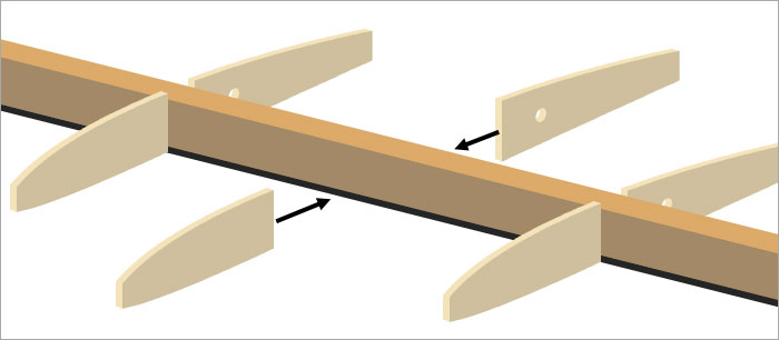
In this technique, the spar is completed first using a strip of continus shear web material. This is ideal for constructing spars wrapped with 45° bias fiberglass or various tube/sock wraps. The advantage is the ribs don't get in the way while you're doing the wrapping, they're attached afterwards.
Bay Webbing - Full Ribs (top cap strip not shown)
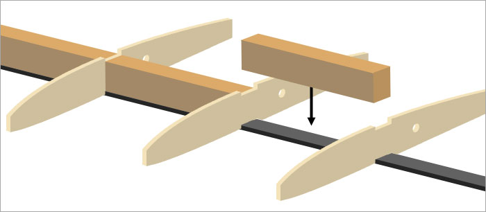
Using this technique the ribs & webbing are added in alternating order to the bottom cap strip. The advantage here is you can use full ribs, which on non-flat bottomed airfoils like the SD 7037, helps assure things stay aligned. Obviously trying to slip a tube wrap over the spar with all those ribs in the way isn't an option. However you can still wrap it using Kevlar thread or ribbon (tow).
I like both techniques but I think I'm going to go with the second. Seeing as this is a tapered wing, I'll need to construct a jig to accurately cut the shear webs but that sounds like a fun challenge. I'll be doing the same thing for the outer panels but with thinner/narrower CF. Will likely ease up on the Kevlar wrap out there too. Anyway I'm liking the direction this is going.
It took me a little while to realize there's two ways to go about building my new spar...
Continuous Webbing - Split Ribs (top cap strip not shown)
In this technique, the spar is completed first using a strip of continus shear web material. This is ideal for constructing spars wrapped with 45° bias fiberglass or various tube/sock wraps. The advantage is the ribs don't get in the way while you're doing the wrapping, they're attached afterwards.
Bay Webbing - Full Ribs (top cap strip not shown)
Using this technique the ribs & webbing are added in alternating order to the bottom cap strip. The advantage here is you can use full ribs, which on non-flat bottomed airfoils like the SD 7037, helps assure things stay aligned. Obviously trying to slip a tube wrap over the spar with all those ribs in the way isn't an option. However you can still wrap it using Kevlar thread or ribbon (tow).
I like both techniques but I think I'm going to go with the second. Seeing as this is a tapered wing, I'll need to construct a jig to accurately cut the shear webs but that sounds like a fun challenge. I'll be doing the same thing for the outer panels but with thinner/narrower CF. Will likely ease up on the Kevlar wrap out there too. Anyway I'm liking the direction this is going.
05-31-2012, 12:43 PM
#19
Senior Member
ORIGINAL: Nodd
I like both techniques but I think I'm going to go with the second. Seeing as this is a tapered wing, I'll need to construct a jig to accurately cut the shear webs but that sounds like a fun challenge. I'll be doing the same thing for the outer panels but with thinner/narrower CF. Will likely ease up on the Kevlar wrap out there too. Anyway I'm liking the direction this is going.
I like both techniques but I think I'm going to go with the second. Seeing as this is a tapered wing, I'll need to construct a jig to accurately cut the shear webs but that sounds like a fun challenge. I'll be doing the same thing for the outer panels but with thinner/narrower CF. Will likely ease up on the Kevlar wrap out there too. Anyway I'm liking the direction this is going.
With your present choice of webbing being as wide as the CF spar caps, simply choosing an adequate thickness of CF can easily make the wrapping extra effort. But as you say, the time spent crafting things can be quite rewarding and isn't really 'extra effort'.
05-31-2012, 01:06 PM
#20
Senior Member
Join Date: Apr 2010
Location: Fort St. John,
BC, CANADA
Posts: 122
Likes: 0
Received 1 Like
on
1 Post
Yeap seems I learned that the hard way. Its interesting that in therory, reinforcing just a small section of an otherwise sound wing could actually cause it to fail.
Ireally like the "second" spar idea in you pictures. Like you mentioned, to keep the wing aligned using two piece ribs would be tricky. Besides, if you use one piece ribs, and then just make your shear webs so they fit nice and snug enough between each rib, the end result really won't be any weaker than the solid spar/split ribdesign. Especially with your carbon spar caps. This time around I doubt you will have any issues!!!
05-31-2012, 02:20 PM
#21
Senior Member
Join Date: Jan 2011
Location: Cody,
WY
Posts: 294
Likes: 0
Received 0 Likes
on
0 Posts
I've done many rounds of spar tests with carbon caps. The most common form of failure is the debonding of the carbon caps from the shear web. This is why wrapping is so important. It prevents the cap under compression from buckling away from the web and causing a bond failure.
The shear forces on the web are diagonal to the length of the spar. For this reason the grain orientation of a balsa shear web, be it horizontal or vertical, isn't that crucial. In my testing the vertical grain was only 3-4% stronger. Since this testing I've done spars with horizontal grain balsa that have sustained high g's during dynamic soaring. If you wrap the spar with bias cut glass then the fibers are more directly aligned with the shear forces. This means that you can make a thinner spar/web which is lighter. If the rib pass through the web then the bias glass is a waste in respect to the shear strength of the web. The weakness of a spar with ribs that pass through the web is the shear strength of the rib itself. In this scenario the grain orienation of the rib is in the absolute weakest orientation to handle shear forces.
1) If each aspect of the spar construction exceeds the forces involved then the spar is functional.....even if the construction methods are less efficient. The spar is just heavier than it needs to be.
2) If the carbon spar caps fail (compression) before the shear strength of the web is exceeded then the web construction is periphery.
3) If the bond between web and cap fails then the cap strength and web shear strength is periphery.
4) A spar construction method only becomes stronger if you strengthen the weakest portion of the design.
05-31-2012, 05:33 PM
#22
Senior Member
ORIGINAL: Nodd
Spar Confusion
It took me a little while to realize there's two ways to go about building my new spar...
Continuous Webbing - Split Ribs (top cap strip not shown)
[img][/img]
In this technique, the spar is completed first using a strip of continus shear web material. This is ideal for constructing spars wrapped with 45° bias fiberglass or various tube/sock wraps. The advantage is the ribs don't get in the way while you're doing the wrapping, they're attached afterwards.
Bay Webbing - Full Ribs (top cap strip not shown)
[img][/img]
Using this technique the ribs & webbing are added in alternating order to the bottom cap strip. The advantage here is you can use full ribs, which on non-flat bottomed airfoils like the SD 7037, helps assure things stay aligned. Obviously trying to slip a tube wrap over the spar with all those ribs in the way isn't an option. However you can still wrap it using Kevlar thread or ribbon (tow).
I like both techniques but I think I'm going to go with the second. Seeing as this is a tapered wing, I'll need to construct a jig to accurately cut the shear webs but that sounds like a fun challenge. I'll be doing the same thing for the outer panels but with thinner/narrower CF. Will likely ease up on the Kevlar wrap out there too. Anyway I'm liking the direction this is going.
Both are excellent designs.
Do you have a drawing that shows how the design of the wing joiners lays out? ....how the joiner rods are tied to and supported by the center section?
05-31-2012, 08:05 PM
#23
Thread Starter
Join Date: Feb 2012
Location: Fairfield, CT
Posts: 416
Likes: 0
Received 0 Likes
on
0 Posts
This time its between the spars!
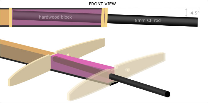
I'm not locked into using an 8mm CF rod but that sounds about right & according to my CAD software, should fit. Currently my plan is for a 7" (17cm) rod length, that will extend one rib bay into each wing panel. The hardwood block will be wrapped it plenty of Kevlar tow, epoxy, fiberglass & anything else I can think of to make sure it stays together. Will probably insert some sort of tubing into the block so that the rod fits consistently (I know humidity will wreak havoc with the size of the hole if I don't line it with something). Well that's the plan for now.
I'm not locked into using an 8mm CF rod but that sounds about right & according to my CAD software, should fit. Currently my plan is for a 7" (17cm) rod length, that will extend one rib bay into each wing panel. The hardwood block will be wrapped it plenty of Kevlar tow, epoxy, fiberglass & anything else I can think of to make sure it stays together. Will probably insert some sort of tubing into the block so that the rod fits consistently (I know humidity will wreak havoc with the size of the hole if I don't line it with something). Well that's the plan for now.
06-01-2012, 09:14 PM
#24
Join Date: Oct 2002
Location: Chilliwack, BC, CANADA
Posts: 12,425
Likes: 0
Received 22 Likes
on
19 Posts
Nodd, when I've done rods of this sort I build the whole wing with some brass or aluminium tubing in there that will be a nice fit for the wires or rods. I put a "cutting shim" between the facing ribs so I can later pull it out and have clearance for a razor saw blade to fit and cut the tubing.
By doing the wing panes as a temporary one piece I am certain that the slip tubes for the joiner rods are fully aligned.
Lat but not least. On the bays with the joiners I don't use webbing between the caps. Instead I mix up a batch of epoxy thickened with phenolic or glass micro balloons to thicken the resin and pack it in between the spars. Before it can run out I cap and clamp 1/32 ply outside "webbings" in place to provide a dam to hold the thickened resin in place. When it cures the resin itself becomes the full webbing for those rib bays as well as ensuring that the bending loads are correctly transferred to the carbon or spruce caps.
Once all that is done I also face the balsa face ribs and sheeting edges with full profile face rib of 1/32 ply. It really cuts down on the usual dings that WILL occur to the fragile edges otherwise. If you can leave the tubing a little proud so it sticks out through those face ribs and then file it down so much the better.
The same treatment goes for the alignment wire slip tubes that generally sit back a bit towards the trailing edge. Or since you are using flaps at the hinging spar along the flap hinge line.
I'm not sure if this matches your intended plan of attack but if there's some ideas in there you can use by all means steal them....
06-01-2012, 09:58 PM
#25
Thread Starter
Join Date: Feb 2012
Location: Fairfield, CT
Posts: 416
Likes: 0
Received 0 Likes
on
0 Posts
Wow awesome suggestions! This is precisely why I'm doing this build in public. I have my own small bag of tricks I enjoy sharing but I love how this works both ways.
For my last ill fated wing I did something a little different to your temporary one piece wing alignment method. Basically I made the wing-rod holes in my ribs slightly over sized on one wing panel. I then assembled the two panels, made sure they were aligned & then used epoxy to fill in the gaps between the wing-rod tube & the over sized holes in the ribs. I was wondering how on Earth I was going to align things this time around but you've just solved that problem for me. Very cool.
We're involved in a debate over on RC Groups about whether my wing-rod blocks would benefit from extra outside ply webbing. Even though your 1/32" ply isn't structural, I think you just wrapped up that discussion for us too with your micro balloon soup rod-block technique. I really like the idea of a self aligning fluid block instead of hours spent drilling holes in hardwood until things come out right. Very smart.
That & your other suggestions, good stuff. Thank you again.