


CDI gr8flyer55

 09-16-2012, 04:02 AM
#302
Senior Member
Join Date: Aug 2011
Location: Moscow,
ID
Posts: 144
Likes: 0
Received 0 Likes
on
0 Posts
Good catch Gompy. (I've added you to the credits for the next version BTW) I do too much cutting and pasting.
I've updated the webpage a bit. Hopefully it will make getting started a little easier.
I'm not sure about the hex file issue. It could be a format problem. MPLAB uses the Intel hex format, which includes config bits at the start and specifies the memory addresses for the values. It could be a problem with certain programmers expecting a different format. Maybe it wants some sort of binary or ELF format hex file.
I do know that it work well through MPLAB with a PicKit2 style programmer. There are cheap clones of this that can be had for $10-20.
I use one of these programmers...
I bought the iCP02 on ebay for $10-12, then ended up also getting the iCP07 board to go with it for around $7.
Here are the links to what I have...
You really don't need the 3.3v option so you can save a few bucks there. You might also save a little by getting the package that includes the socket instead of getting themseparately, and if you bid on ebay you can also save a few bucks that way. The iCP07 board just worked out well for me since I can power and program it from the USBwhile connected to the timer board.
What I did was take out the processor socket on John's timer board and put in another one that had really long pins. I connect those pins to the iCP07 board (not all of them, just the needed ones!). That way I can program and power the iCP07 while connected to the timer board. I just have to pull the CDI power each time I want to reprogram otherwise it gives me an error.
In any case, I suggest investing in a programmer. It should only set you back around $15-25 depending on your options and if you want to snag one by bidding on ebay. It supports pretty much every PIC processor out there and works through MPLAB.
09-16-2012, 04:04 AM
#303
Senior Member
Join Date: Aug 2011
Location: Moscow,
ID
Posts: 144
Likes: 0
Received 0 Likes
on
0 Posts
> OK I have been playing with the spreadsheet and in the table that I paste in code I get a lot of negative numbers. Jake do you know why?
Email it to me and I'll take a look.
Email it to me and I'll take a look.
09-16-2012, 04:49 AM
#304
Senior Member

Join Date: Jul 2010
Location: Alkmaar, NETHERLANDS
Posts: 404
Likes: 0
Received 0 Likes
on
0 Posts
BTW, befor instal MPlabs and compiler you have to uninstall / remove all old files.
MPlabs will collect al you need by them self.
After instal MPlabs you have to install the compiler.....not befor or with old MPlabs version.
If you still have done, you have to remove also the compiler files.
MPlabs will collect al you need by them self.
After instal MPlabs you have to install the compiler.....not befor or with old MPlabs version.
If you still have done, you have to remove also the compiler files.
09-16-2012, 04:59 AM
#305
Senior Member
Join Date: Nov 2005
Location: Hamburg,
PA
Posts: 805
Likes: 0
Received 0 Likes
on
0 Posts
Rob, I saw the wrong pic chip number as I was going thru the steps the first time and changed it as I was going thru them to do the process. I think now that my programming software is giving me a problem with the Intel format of the hex file. I was using pic4u software. Trying something else today. Hope it works.
John
John
09-16-2012, 05:11 AM
#306
Senior Member
Join Date: Jul 2010
Location: Alkmaar, NETHERLANDS
Posts: 404
Likes: 0
Received 0 Likes
on
0 Posts
This will be a normal 2stroke ignition curve.
Started at ~5 degrees BTDC (easystart), at 1000 rpm back to the factory settings of the ignition (~28 degrees BTDC) and when speedup back to ~5 degrees BTDC.
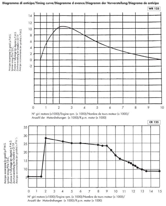
Started at ~5 degrees BTDC (easystart), at 1000 rpm back to the factory settings of the ignition (~28 degrees BTDC) and when speedup back to ~5 degrees BTDC.
09-16-2012, 07:07 AM
#307
Senior Member
Join Date: Nov 2005
Location: Hamburg,
PA
Posts: 805
Likes: 0
Received 0 Likes
on
0 Posts
Jake, i think I fixed my software problem!
My old programming software was the culprit!!
I was using Picprog4u as the software and it gave me overflow and math errors.
Sooooo, I downloaded new software. picpgm for windows.
It autodects my board as a JDM board but works anyway!
It also autodetects the pic chip! This is a vast improvement over the old software where everything was manually selected. Now I have my 4k file program in the pic chip and am about to test on my test engine. Results in my next post !!!
John
09-16-2012, 07:10 AM
#308
Senior Member
Join Date: Aug 2011
Location: Moscow,
ID
Posts: 144
Likes: 0
Received 0 Likes
on
0 Posts
Great curves Gompy.
NOTE!!!! - COM found some errors in the spreadsheet calculations. I'm working on it now. There were a couple places where I converted degrees to digi-degrees backwards.
So everybody hang tight for the moment!
NOTE!!!! - COM found some errors in the spreadsheet calculations. I'm working on it now. There were a couple places where I converted degrees to digi-degrees backwards.
So everybody hang tight for the moment!
09-16-2012, 07:33 AM
#309
Senior Member
Join Date: Nov 2005
Location: Hamburg,
PA
Posts: 805
Likes: 0
Received 0 Likes
on
0 Posts
Well, it runs my engine but the curve deftly needs tweaking that I am using!!
Engine kicks back at starting, hesitates badly on acceleration and top end is alot lower than Nyemi's hex file with MSD.
Maybe the new changes you are making will fix some of it but I am programming a new curve in a few minutes to try first before making any changes to the software itself.
John
Engine kicks back at starting, hesitates badly on acceleration and top end is alot lower than Nyemi's hex file with MSD.
Maybe the new changes you are making will fix some of it but I am programming a new curve in a few minutes to try first before making any changes to the software itself.
John
09-16-2012, 07:47 AM
#310
Senior Member
Join Date: Nov 2005
Location: Hamburg,
PA
Posts: 805
Likes: 0
Received 0 Likes
on
0 Posts
I was also noticing that we need some finer adjustments at the starting rpm of the curve. It takes too large of a jump in rpm versus advance available. Maybe some 1/2k increments would do the trick, not sure. Nyemi's curve has finer adjustments. His curve works excellent. The one I use is the Rcxel curve. Perfect for 2 strokes. We used it on the DA dyno runs at Boyesen and all data collected reported it was "THE" absolute best running curve to date.
If I can duplicate that curve in our new data line, that would be the icing on the cake, so to speak.
John
If I can duplicate that curve in our new data line, that would be the icing on the cake, so to speak.
John
09-16-2012, 08:22 AM
#311
Senior Member
Join Date: Aug 2011
Location: Moscow,
ID
Posts: 144
Likes: 0
Received 0 Likes
on
0 Posts
I think I fixed the errors in the spreadsheet. New version (rev3) is on the website.
It seems to work well in the simulator.
You need to check that it's not giving you negative values in the Calc. Load column on the Table Values sheet.
I'll try to make it a little more user friendly in the future.
I should probably figure out better ways to make sure the settings are right.
One thing to point out is that if your hall sensor is at 30 deg, you can't have a 30 deg advance setting!
There needs to be at least 43 uS of delay after the sensor input before the processor can fire the spark.
09-16-2012, 11:14 AM
#312
Senior Member
One thing to point out is that if your hall sensor is at 30 deg, you can't have a 30 deg advance setting!
Why? Can't you just have no delay?
Anyway I tried out the latest spreadsheet and I have a new problem. Now at 5000 rpm the ignition stops firing. below 5000 it starts again. Also the curve is no a smooth transition
it bounces from full retard to full advance.
09-16-2012, 12:14 PM
#313
Senior Member
Join Date: Aug 2011
Location: Moscow,
ID
Posts: 144
Likes: 0
Received 0 Likes
on
0 Posts
Once the sensor interrupt triggers the PIC has to decide how long to delay. By the time it decides essentially about 43 uS have elapsed. If it sets a timer compare value that has already passed it will not generate the interrupt to fire the spark.
Thanks for testing things. It's possible I screwed up somewhere between the code and spreadsheet. I'll keep working on it.
Thanks for testing things. It's possible I screwed up somewhere between the code and spreadsheet. I'll keep working on it.
09-16-2012, 01:24 PM
#314
Senior Member
Join Date: Nov 2005
Location: Hamburg,
PA
Posts: 805
Likes: 0
Received 0 Likes
on
0 Posts
I've just finished trying to compile the new source code. There are way too many errors to wade thru now for me. I got syntax errors, init variable errors and about 30 total other errors in lines I have no idea how to edit out.
Anyone get all these new errors? The previous source compiled fine with my advance values being the only thing changed.
Don't know what to do now. I guess maybe go back to version 2 and keep trying my new curves only, since that one at least runs my test engine.
Charlie, the file you sent me compiled fine also. Just changed the curve. It seems that if you edit any other blocks in the excel sheet at all besides the advance, it screws something up. Not sure why yet.
Lots of work now that we have two of us actually testing things. I'm making one last hex for today and run the engine, will post results, good or bad.
John
09-16-2012, 04:13 PM
#315
Senior Member
Join Date: Nov 2005
Location: Hamburg,
PA
Posts: 805
Likes: 0
Received 0 Likes
on
0 Posts
Hey guys!!!
Just programmed my final pic chip for today. Took it outside to the engine test stand and plugged it into the timer board. Flipped on the power, primed the engine, one 2 finger flip and it roared to life!
Beauuuutiful idle, instant transition to high throttle and I gained another 200 rpm!
This one is a keeper.
Went back to the second source file that compiled with no errors, edited my curve in excel, pasted and ran MPLAB x for the compile. There were missing symbols, so I used the suggested fixes mplab's debugger gave me(great help hints by hitting alt-enter), fixed them all and compiled with no errors!!!!
I was ecstatic! Tears of joy. I have now what I consider to be a great advance curve. I will test again tomorrow but this hex file definitely works on my engines without a doubt!
Thanks Jake !!
John
09-17-2012, 12:10 AM
#316
Senior Member
Join Date: Jul 2010
Location: Alkmaar, NETHERLANDS
Posts: 404
Likes: 0
Received 0 Likes
on
0 Posts
I ask Jake todo the same with the Exelsheet we (JMJ and I) do befor.
Into the first tab the curve generator and into the second tab the complete code with the changes you have make into the first tab.
Only a copy / past from the code of tab two into MPlabs to compile must do the job without any faults.
Into the first tab the curve generator and into the second tab the complete code with the changes you have make into the first tab.
Only a copy / past from the code of tab two into MPlabs to compile must do the job without any faults.
09-17-2012, 01:23 AM
#317

Join Date: Mar 2009
Location: xnot applicable, AUSTRALIA
Posts: 293
Likes: 0
Received 0 Likes
on
0 Posts
Quick question on the circuit diagram.
There is an additional diode (obvious) but what is the red square around the 2 diodes in BR1 all about..??
There is an additional diode (obvious) but what is the red square around the 2 diodes in BR1 all about..??
 09-17-2012, 02:49 AM
#319
Senior Member
Join Date: Jul 2010
Location: Alkmaar, NETHERLANDS
Posts: 404
Likes: 0
Received 0 Likes
on
0 Posts
ORIGINAL: jakestew
One thing to point out is that if your hall sensor is at 30 deg, you can't have a 30 deg advance setting!
One thing to point out is that if your hall sensor is at 30 deg, you can't have a 30 deg advance setting!
The highest I can find will be 23 degrees BTDC, this will be a very large engine and a low rpm runner.
This kind of engines need the time after ignition to burn all the petrol.
Our engines, 25 till 50 ccm have 18 or maybe 20 degrees BTDC.
Why we will the pickpuppoint to 40 degrees...we need the time to calculate the real ignitiontime.
The real ignition it selfs must be between 0 and 40 degrees BTDC, above 40 degrees BTDC is not possible.
BTW, forget multi spark.
Into a big room you need multi bulbs to light up te room
Into a small room you need only one bulb to light up te room and sometimes even one bulb is given to much light.
Our engine have a very small cilinder and we put less petrol into this engine like they do in cars.
Both engine have one cancle to spark up the petrol.
Into the car engine the have to fire a lot of petrol, so they need more sparks to burn all petrol.
Our engines have also one cancle, but the petrol we put into our cilinder is lees then they use into a car engine.
So why do we need multispark........it takes only energie we need so bad for this one heavy spark we can make with the HV-board.
09-17-2012, 03:07 AM
#320
Senior Member
My Feedback: (1)
Join Date: Nov 2002
Location: Netanya, ISRAEL
Posts: 139
Likes: 0
Received 0 Likes
on
0 Posts
Hi John,
Can you share with us your ignition curve ?
Can you post all 3 spreadsheet (setup, table and graph) in pdf format ? think is accepted by forum.
Can be a good start point for us.
Thank,
Dino
Can you share with us your ignition curve ?
Can you post all 3 spreadsheet (setup, table and graph) in pdf format ? think is accepted by forum.
Can be a good start point for us.
Thank,
Dino
09-17-2012, 04:02 AM
#321
Senior Member
Join Date: Nov 2005
Location: Hamburg,
PA
Posts: 805
Likes: 0
Received 0 Likes
on
0 Posts
All of my edited and working files will be posted on Jake's website sometime today.
I'm happy with what I have working now. When I have time after work today, I'm going to try a video of how easy the engine starts and the lack of noticeable vibration throughout the whole rpm range etc.
Working 2 days a week gives me money for this hobby. Since I retired earlier this year, I've had time to develop the ignition and advance circuit boards. It may seem that I've gotten instant success lately, but it's been a very rocky road to the top. I want to personally thank all of the people involved in this project. Rob, you were my inspiration by giving up your time and helping develop the timer from the start. Jake, you've done a tremendous among of work on the software. Charlie, thanks for your input and sharing expertise in edits and trial versions and parts. There are many more of you as is evident by the thousands of posts in the forums. This is not the end however! Much work in different directions by contributors is still ahead. My main goal was a complete working ignition system, easy to build and maintain, and customizable by the end user. I've sent out many systems to people who've requested them and will continue to do so. I will be writing a detailed info-text on edits, what the effects are on running characteristics, and why one person's system would not be a cure all for everyone.
What I have experimented with was Nyemi's idea of multi-spark. I have many programmed pic chips with different settings. What I settled on for now is MSD with only 2 sparks up to about 3500 rpm, easy start angle of 4 degrees, and my edited 2 stroke curve. Like I said, my curve is working great. No misfires, plenty of spark energy thru the whole rpm range and reliability.
This is a starting point and as Jake experiments more, things are only going to get better!!
John
09-17-2012, 04:57 AM
#322
Senior Member
Join Date: Jul 2010
Location: Alkmaar, NETHERLANDS
Posts: 404
Likes: 0
Received 0 Likes
on
0 Posts
I changed the Exelsheet a bit with the extra code tab.
It's not ready yet, but I hope Jake understand wat I mean with it.
I dont want to change to much, maybe Jake have other ideas.
link http://www.bucket.gompy.net/v0.9b3_rev3_incl_code.xlsx
The change will be, the values of the curve will be writen direct to the code into the code tab.
Not good
#define Dwell_Time 500 // Dwell time, in uS, that output is kept on
Better
#define Ignition_Time 500 // Inigtion time in uS, SRC output is kept on
500 uS can be reduce to 250 uS
I don't know wat todo with this
#define MSD_Spark 3 // Total number of sparks per revolution when RPM is below Max_MSD_Rev (at least 1)
#define MSD_Low_Spark 4 // Total number of sparks to fire when in LowRPM mode (below 915 RPM)
#define MSD_Start_Spark 5 // Total number of sparks to fire on the first start spark
#define MSD_dDeg 5 // DigiDegrees between multisparks (1 = 1.4 deg)(dwell time not accounted for)
#define Max_MSD_Rev 79 // Maximum RPM (in terms of CurrentRev + 1) to use MSD (78 = 3,005)
If you ask me personal, leave it out of the code or only 2 sparks max at low (<2500) rpm.
09-17-2012, 10:01 AM
#323
Senior Member
Join Date: Aug 2011
Location: Moscow,
ID
Posts: 144
Likes: 0
Received 0 Likes
on
0 Posts
This is all very good news! After the rocky start I was worried there would be nothing but problems.
John's results seem like proof of concept to me! I'm not sure about the errors he was getting compiling yet, but it's great to see people getting things working and posting back.
In the future, if you do NOT want something you email me posted to the website please let me know. Otherwise I think it can only help to keep posting everything there.
Gompy, I do like the idea of having the spreadsheet generate the code. At the very least it will be good to have it generate the whole user settings/curve table section. I'll work on getting that done.
I know you don't like the multispark, but I think it's worth keeping as an option. You can always turn it off and it doesn't waste any significant processor time. I think that any CDI circuit is going to be different, and some may be capable of delivering sparks very fast. The setup John sent has a partly bad coil, I had a random large spark gap (bare wires), and I still could fire it every 4ms. I think with a proper gap and a good coil it could fire a lot faster. I proper resistor spark plug might also make a difference.
I also think there's other applications for the MSD. If your spark doesn't fire the first time, maybe a spark just after TDC would at least clear the cylinder and burn the fuel.
Don't let me discourage you from discouraging us though. It's good for people to know when us young pups are trying something silly, and I don't want people to think this is some amazing feature when it might not work at all.
COM, I thought about your comment and I think you're right. The software should not just skip sparks that it can't throw on time. I didn't think much about how this would cause problems for high advances at different RPMs. I was only thinking about it being a problem at very high RPMs. I'll rework the code so that it will just throw a spark right away if it can't time it.
My plan for the future is to stick with the 683 for awhile, until I'm sure it's working as good as possible and I've maxed out it's capabilities for features. The code should directly port to the 1840 with no problems, aside from some adjustments for higher running frequency.
I have a few ideas left for the 683. Please comment on what you think of them so I don't end up wasting time on something silly...
****I need to rework the MSD delay degree idea. I think that was a bust. My idea was to space out the sparks as much as possible so they would have the best chance. I thought that the best idea would be to throw the first spark proper, then the next at half way to TDC, then the final at TDC, and/or maybe even sparks after TDC. My thought was that even a late spark would burn off the fuel, which would hopefully be cleaner and better prepare the cylinder for the next spark. It might also give a little power to keep the engine turning so it doesn't sputter out.
My understanding is that it is harder to spark as cylinder pressure goes up. So my thought was that if it didn't fire at the right spot maybe it was because the fuel was late or not vaporized enough, if it didn't fire at TDC maybe it was because the pressure was too high, but ATDC it might have a chance to fire.
I need to know what people think about how best to time the MSD sparks. Set delay between them or somehow spaced based on RPM?
****I'll get two ignition tables loaded at the same time so you can switch between them. I think there's no better way to test curves than switching back and forth and seeing how it runs. People might also want to run the same ignition on multiple engines. There's room for probably three curves, and I might try to get three loaded at some point too. Pins 2+3 aren't used and pin 4 is grounded, so the switch/jumper will probably go between 2-3 or 3-4.
****If anyone has looked at the code closely you might have noticed that I save CurrentRev to LastRev for no apparent reason. I'm thinking about adding a feature that uses the RPM from the last spark to tell if the engine is accelerating or decelerating and use that to predict the delay a little more precisely.
If anyone knows about the different speed throughout the cycle please share. I think that the 30-0 revolution speed is probably less than the speed of the whole revolution. Inertia from the flywheel should smooth things out, but how well does it work? Also what about people milling their flywheels down or running with none at all?
If the engine is accelerating I think the 30-0 speed is probably very close to the total rev speed. But if it's slowing down I think the 30-0 could be a lot slower than the total.
Can someone also set their curve to flat (all the same advance value) and see how steady the timing is? I'm curious if it's real steady or if it doesn't track well when revving or letting off the throttle.
I think it might also be possible to have the engine slow down faster by retarding the spark. Some people might like this. The way it would work is that if the processor detects that the CurrentRev is a lot less than the LastRev it will know you have let off the throttle and will retard the spark to produce less power, thus slowing the engine faster.
****Another idea I plan is to shorten the table to only what is needed for the high RPMs and start calculating the delay on the fly for the rest of the range. If I can calculate at least up to the idle and a little bit of the takeoff from idle I think that will help.
Using a table you can only have so many values. This limits how precisely I can use the timer value.
Right now I have about 128 uS resolution throughout, but I should hopefully be able to get down to a few uS resolution in the calculated range.
The other strategy for this would be to use the high bits of the timer for a table lookup as I do now, then use the low bits to determine the position between table values, then calculate how much time to add. This would take too much processing time I think.
****A RPM limiter is another thing I would like to add. Cutting off, skipping every other, or retarding the spark are the methods I can think of for this. Advice requested.
One interesting thing I noticed about the curent code is that when the RPM goes too high to time the spark it skips every other spark. It just happened to work out this way. But as COM seemed to figure out, this could also happen if your advance was set too high. That would make you run really rough.
****The only other thing I can think of for the 683 is using the sleep mode to save some power. The processor should be able to sleep through 330 degrees of engine revolution. If I can reduce the power consumption by over 90% (330/360) I think that would be worthwhile.
The GP2 interrupt should wake the processor from sleep mode, but the timers don't run in sleep without an external clock source. We would need some sort of crystal to keep the timer going and that would tie up more pins. A crystal is more stable and less temperature sensitive, so it might be something to think about for the future. Tying up two extra pins on a 8-pin processor probably isn't worth it though.
So keep the comments comming! That's what keeps me going and how I learn what I need to know for this project.
-Jake
P.S. John's tested and working version is up on the website. I might get some time to get a few things done tonight.
09-17-2012, 10:42 AM
#324
Senior Member
Join Date: Jul 2010
Location: Alkmaar, NETHERLANDS
Posts: 404
Likes: 0
Received 0 Likes
on
0 Posts
The flyback we use can't generate enough power to make multi sparks.
The transformer is much to small to load the capacitor between two sparks.
A other isue will be the pressure into the cilinder from this small engines.
Into the cilinder you have ~6 bar and need about 30 mJ to generate a small spark.
If tested outside the cilinder you have a spark, but not when the engine runs.
So you wast power for the next real spark you want to have.....not good.
At high rpm the time to load the capacitor will again shorter, less power to load the capacitor.
The flyback don't have enough time and power to load the capacitor.
Thats why you can't run high rpm with the multispark option.
Use multi spark with low rpm at start, it don't do any thing......next spark will be after TDC.
All petrol wat is not burn is allready find the way out, why do we want to ignite this petrol ?
It isn't I don't like multi spark, but when you lost power (get small spark) it's better not to use multi spark for small engines.
09-17-2012, 11:19 AM
#325
Senior Member
Join Date: Feb 2010
Location: szarvas, HUNGARY
Posts: 133
Likes: 0
Received 0 Likes
on
0 Posts
Hi Jake
I congratulate, excellent work.
But RC Ignition uses a Hall input rising edge.
GPIO = sGPIO.ALL; // Shadow GPIO -> GPIO
OPTION_REG = 0b11000000; // pullups off, GP2 input(hall)6 bit=falling edge=0, rising edge=1, Tmr0
CMCON0 = 0b00000111; // comparator config, disable
CCP1CON = 0b00000000; // CCP off, special event mode = 1011 (resets Timer1)
T1CON = 0b00010100; // TMR1 Off, 1:2 prescaler
TMR1 = 0; // Zero Timer1
falling edge=OPTION_REG = 0b10000000;
rising edge= OPTION_REG = 0b11000000;