


Great Planes Giant Ugly Stick
 03-21-2013, 05:48 PM
#451

My Feedback: (1)
Join Date: Jan 2008
Location: Arlington,
TX
Posts: 535
Likes: 0
Received 0 Likes
on
0 Posts
ok so im at the point of drilling the fire wall for the motor mount, i found a template online for the DLE 35RA since it dont come with one. Now when I place the template on the firewall and line it up it seems to have the engine shifted over to the right side so is that normal? I need to know before I drill. Heres a pic of the template and what Im talking about. Now my firewall has been painted black so the cross lines are hard to see but they are lined up with the ones I made on the template. 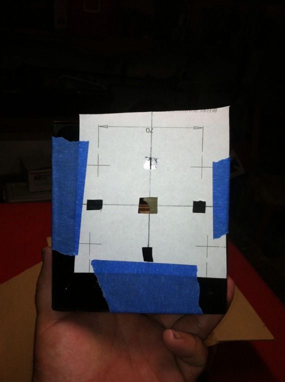
 03-21-2013, 06:28 PM
#452

Join Date: Nov 2005
Location: Poolesville, MD
Posts: 12,624
Likes: 0
Received 0 Likes
on
0 Posts
Ok, just to clarify things...
You say it is "shifted to the right". That is incorrect, it is shifted to the LEFT.
Always give directions as if you were sitting in the airplane cockpit. You are looking at the template from the front, which is why you think it is shifted to the right...
Now with that said...
When the engine is mounted the firewall provides a bit of a rightward angle ( as seen from a pilot ) called "right thrust".
This helps compensate for the normal pull to the left of the engine.
To make sure the spinner sits just about in the center of the airframe, the engine mount is shifted to the left a bit.
So everything is correct if you have resized your template properly.
I highly recommend that you mark the position of the crosses with an awl but DO NOT drill right away.
Next mount the standoffs on the engine, put bolts on the standoffs and make sure everything lines up with the standoff bolts and the awl holes.
Then determine exactly where you will put the throttle rod and fuel line holes... again establish all of this BEFORE you begin drilling.
Plan, check and measure again, and finally drill.
As you drill lessen the amount of force as you near penetrating the firewall so you will tend not to break the thin wood veneer in the back.
Also if you are using standoffs, consider using fender washers to spread out torsional loads.
I've built just a few of these planes ( I'm on number six now! )
 03-22-2013, 08:30 AM
#455
My Feedback: (1)
Join Date: Jan 2008
Location: Arlington,
TX
Posts: 535
Likes: 0
Received 0 Likes
on
0 Posts
Ok thanks guys, I thought that's what the deal was but just needed to be sure, what kind of lock tight should I use on the motor mounts? Blue is the best choice I think but thinking I need to go with the red on the muffler what's some opinions about that? Also what are you guys useing for a choke handle/switch?
03-22-2013, 09:32 AM
#456
Join Date: Nov 2005
Location: Poolesville, MD
Posts: 12,624
Likes: 0
Received 0 Likes
on
0 Posts
Definitely blue on the muffler if you ever want to remove it!
I've had good luck with it on mufflers.
For my Big Stik ( pictured before ) with a cowl, I used a piece of multi-stranded wire, soldered to a clevis for the engine side.
The exposed side is put through the cowl, and I attach a small wheel collar for a handle. The exposed side is also soldered to prevent fraying.
I don't bother with either a choke handle, switch or servo on the exposed engines, as I only need the choke once a day when the engine is cold.
I use a remote CDI cut off on most gassers and I also set the throttle so that I can kill the engine with the throttle kill as well.
03-24-2013, 12:12 PM
#458
My Feedback: (1)
Join Date: Jan 2008
Location: Arlington,
TX
Posts: 535
Likes: 0
Received 0 Likes
on
0 Posts
ORIGINAL: opjose
Ok, just to clarify things...
You say it is ''shifted to the right''. That is incorrect, it is shifted to the LEFT.
Always give directions as if you were sitting in the airplane cockpit. You are looking at the template from the front, which is why you think it is shifted to the right...
Now with that said...
When the engine is mounted the firewall provides a bit of a rightward angle ( as seen from a pilot ) called ''right thrust''.
This helps compensate for the normal pull to the left of the engine.
To make sure the spinner sits just about in the center of the airframe, the engine mount is shifted to the left a bit.
So everything is correct if you have resized your template properly.
I highly recommend that you mark the position of the crosses with an awl but DO NOT drill right away.
Next mount the standoffs on the engine, put bolts on the standoffs and make sure everything lines up with the standoff bolts and the awl holes.
Then determine exactly where you will put the throttle rod and fuel line holes... again establish all of this BEFORE you begin drilling.
Plan, check and measure again, and finally drill.
As you drill lessen the amount of force as you near penetrating the firewall so you will tend not to break the thin wood veneer in the back.
Also if you are using standoffs, consider using fender washers to spread out torsional loads.
I've built just a few of these planes ( I'm on number six now! )
03-24-2013, 12:38 PM
#459
Member
My Feedback: (58)
Join Date: Jul 2005
Location: SMYRNA,
DE
Posts: 52
Likes: 0
Received 0 Likes
on
0 Posts
Scott42,
I got mine here, http://www.jrhobbyhardware.com/shop/. The spinner in the picture is on a DLE 20, not a 30 or 35. I needed a 5mm X 75mm for my carbon fiber spinner on my GUS and he had it. Shipping is a little crazy but he will refund you the over charge.
You need to get me motivated to work on mine, I have not worked on it in weeks.
Bill
03-24-2013, 02:04 PM
#460
My Feedback: (1)
Join Date: Jan 2008
Location: Arlington,
TX
Posts: 535
Likes: 0
Received 0 Likes
on
0 Posts
ORIGINAL: TunnelBill
Scott42,
I got mine here, http://www.jrhobbyhardware.com/shop/. The spinner in the picture is on a DLE 20, not a 30 or 35. I needed a 5mm X 75mm for my carbon fiber spinner on my GUS and he had it. Shipping is a little crazy but he will refund you the over charge.
You need to get me motivated to work on mine, I have not worked on it in weeks.
Bill
03-24-2013, 03:59 PM
#461

Join Date: Oct 2005
Location: Derry,
NH
Posts: 21
Likes: 0
Received 0 Likes
on
0 Posts
Updates on my low stik... Need to find matching paint for the cowl and build the fake radiator
[link]http://images.rcuniverse.com/gallery/photos/206244/lg-238278.jpg[/link]
[link]http://images.rcuniverse.com/gallery/photos/206244/lg-238278.jpg[/link]
[link]http://images.rcuniverse.com/gallery/photos/206244/lg-238278.jpg[/link]
[link]http://images.rcuniverse.com/gallery/photos/206244/lg-238278.jpg[/link]
03-24-2013, 05:42 PM
#462
My Feedback: (1)
Join Date: Jan 2008
Location: Arlington,
TX
Posts: 535
Likes: 0
Received 0 Likes
on
0 Posts
ok so I have spent the last two days working on just the forward compartment, I built 2 battery trays to hold down the batterys built a servo tray. It dont look like it but theres alot of work in that small space. I still need to install the fuel tank and hook up the reciever also need to hook up the ignition battery but wanting to wait untill I balance the plane so I can putt it where it helps to balance things out. I borrowed a lot of ideas from this very post about the GUS and I really think the ideas all payed off in one way or another. Heres a few pics of the build.
03-24-2013, 05:46 PM
#463
My Feedback: (1)
Join Date: Jan 2008
Location: Arlington,
TX
Posts: 535
Likes: 0
Received 0 Likes
on
0 Posts
please bear with me, my files are to large to upload all at once so I will break it down a bit. Here are my battery trays that I built to hold the batterys down.


 03-25-2013, 04:49 AM
#466
Member
My Feedback: (58)
Join Date: Jul 2005
Location: SMYRNA,
DE
Posts: 52
Likes: 0
Received 0 Likes
on
0 Posts
Cool looking plane, looks like you need skis on it. Spring is coming. I see your covering is about as poor as mine was, the worse covering job I have ever had on a ARF. Bill
03-25-2013, 07:09 AM
#468
Join Date: Oct 2005
Location: Derry,
NH
Posts: 21
Likes: 0
Received 0 Likes
on
0 Posts
ORIGINAL: SCOTT42
Can you guys tell me if the stopper that's supplied with the tank is gas proof? Or do I need to replace it with one that is?
Can you guys tell me if the stopper that's supplied with the tank is gas proof? Or do I need to replace it with one that is?
03-25-2013, 09:50 AM
#470
Join Date: Nov 2005
Location: Poolesville, MD
Posts: 12,624
Likes: 0
Received 0 Likes
on
0 Posts
ORIGINAL: underh2o2long
You need to replace it with a gas one... the one that comes with it is for glow fuel.
You need to replace it with a gas one... the one that comes with it is for glow fuel.
I wonder though... the stopper looks and feels identical to the one sold with the Sullivan conversion kit.
03-25-2013, 10:43 AM
#472
Join Date: Nov 2005
Location: Poolesville, MD
Posts: 12,624
Likes: 0
Received 0 Likes
on
0 Posts
ORIGINAL: ghoffman
You could always test it by putting it in a jar of gas for a day or so.
You could always test it by putting it in a jar of gas for a day or so.
I may just have to try it and see.
03-25-2013, 02:49 PM
#474
Join Date: Oct 2005
Location: Derry,
NH
Posts: 21
Likes: 0
Received 0 Likes
on
0 Posts
ORIGINAL: TunnelBill
Cool looking plane, looks like you need skis on it. Spring is coming. I see your covering is about as poor as mine was, the worse covering job I have ever had on a ARF. Bill
Cool looking plane, looks like you need skis on it. Spring is coming. I see your covering is about as poor as mine was, the worse covering job I have ever had on a ARF. Bill
Yeah, I agree... on both the skis and the covering! Think Spring! I was also surprized by the covering when I got it... GP usually is better than this.... Oh well, I will need to spend some time making it pretty.
David
04-03-2013, 04:00 PM
#475
My Feedback: (1)
Join Date: Jan 2008
Location: Arlington,
TX
Posts: 535
Likes: 0
Received 0 Likes
on
0 Posts
It seems like I had to add 10 oz of lead to the front of my last GUS, I just put the new GUS with the dle 35 on the cg stand and even with these heavy batterys im useing it still comes out that I need to add 10 oz of lead to this gus. Im kinda disapointed that im having to add so much weight to this one, not sure of another way around it.