


Great Planes Reactor ARF .46-.70 - Build Thread
 01-09-2007, 03:59 PM
#26
Senior Member
Thread Starter
Join Date: Jul 2006
Location: Charlottesville,
VA
Posts: 723
Likes: 0
Received 0 Likes
on
0 Posts
Ernie,
Decent servos seem to be so expensive these days, and believe me, it wasn't easy to spend the cash on them, but I figure they'll have a long life in other birds long after the Reactor has passed on. Oh, and for what it's worth, with a little creative use of coupons, they can be had for about $48 a piece, which is not quite as hard to swallow as $60 a pop.
Decent servos seem to be so expensive these days, and believe me, it wasn't easy to spend the cash on them, but I figure they'll have a long life in other birds long after the Reactor has passed on.
Oh, and for what it's worth, with a little creative use of coupons, they can be had for about $48 a piece, which is not quite as hard to swallow as $60 a pop.
 01-09-2007, 04:55 PM
#28
Senior Member
Thread Starter
Join Date: Jul 2006
Location: Charlottesville,
VA
Posts: 723
Likes: 0
Received 0 Likes
on
0 Posts
ORIGINAL: Ernie Misner
Getting those servos through Tower, Erik?
Thanks,
Ernie
Getting those servos through Tower, Erik?
Thanks,
Ernie
01-09-2007, 05:19 PM
#29
Junior Member
Join Date: Dec 2003
Location: champlin, MN
Posts: 8
Likes: 0
Received 0 Likes
on
0 Posts
just wondering on engines,my two choices are a ys 63 or a 82 saito. just recieved my reactor from tower today.(20 gift certificate, 30 rebate, =119 for the plane, couldn't pass it up)I want the plane ultimate 3D.
01-09-2007, 10:57 PM
#30
Senior Member
Thread Starter
Join Date: Jul 2006
Location: Charlottesville,
VA
Posts: 723
Likes: 0
Received 0 Likes
on
0 Posts
Darin, I imagine either of those engine choices would power it about the same. The YS might allow a little more flexibility in tank placement, but the Saito will probably cause less tuning frustration, unless of course, you’re a YS guru.
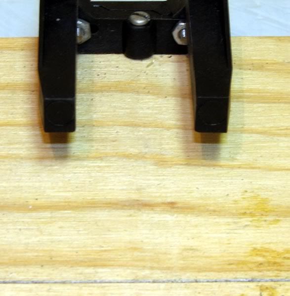
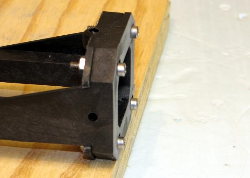
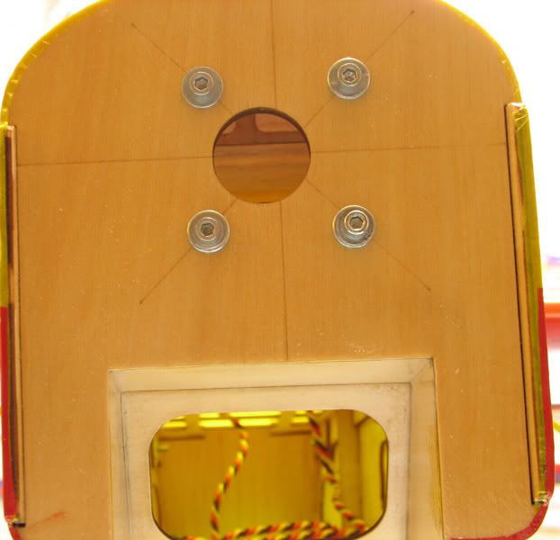
I got the horizontal stab installed, and as far as I can tell it’s damn near perfect. I didn’t have to even LOOK at a piece of sandpaper and it went together exactly parallel with the wing, at least as far as my eyes can tell. The first step was to get the wings on, which is where I ran into my first bit of real trouble with this plane. The right wing panel would not seat properly in the fuse. The first clue something was wrong was when the rear screw on the right side wouldn’t go into the fuse without cross threading. The other three were fine, so I concluded there was a spot of glue or something in the blind nut. I was wrong. Without the wing in place, the 4-40 bolt went in smooth as butter. After lots of head scratching and careful inspection, I figured out what was wrong. The opening for the front anti-rotation pin was not in the exact right location……or alternatively, the front ARP was not properly located on the wing root. Whichever it was, the solution was simple. I used a round file to open up the opening on the fuse so the wing could be nudged forward a hair. I didn’t measure, but we’re talking about less than 1 mm at the most. Here is a pic that explains it better than all those words.
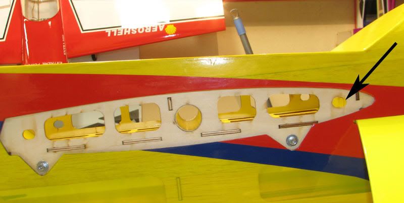
I relieved the front side of the indicated hole, thereby allowing the wing to nudge forward. The fit is still not perfect, and I may end up doing a little sanding in the area of the two tabs through which the bolts pass, but it goes together now, and that’s what I needed in order to get the stab installed.
After measuring to make sure the stab was centered and square, I marked along the fuse with a marker, as instructed.
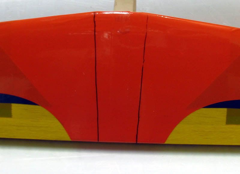
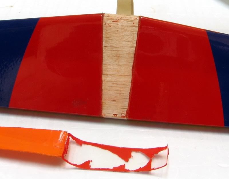
I then used a soldering iron to burn through the covering along the inside of the line and pull off the center section.
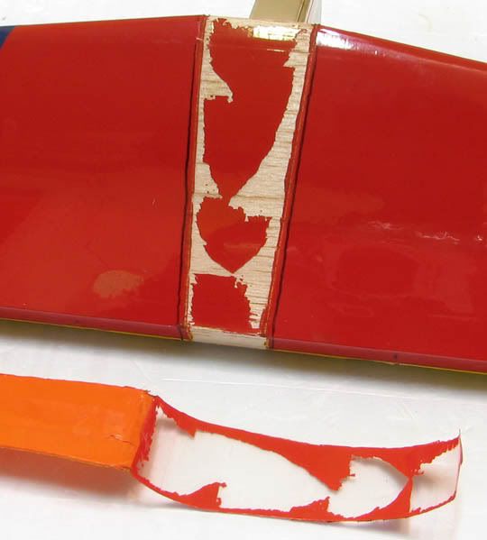
It left a bunch of the pigment behind just like the black trim on the bottom of the wing. Maybe that stuff is MonoKote after all, but I’ve never seen it leave color behind on itself like that. Anyway, after a few minutes spent scraping with a fresh #11, the center was ready to be glued in.
It was a simple affair, but my hands were covered in epoxy, so I didn’t get to take any pics. Here are a couple of pics taken after the fact.
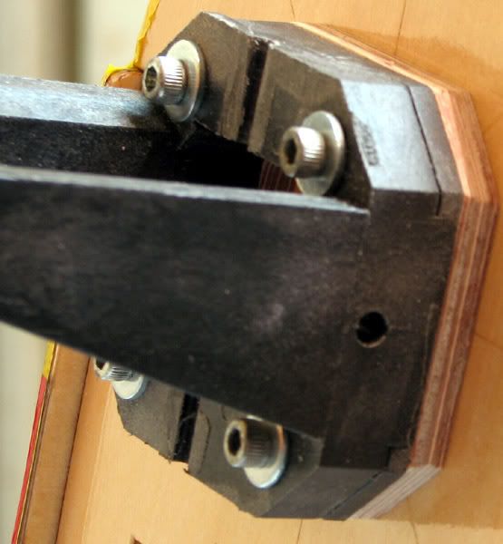
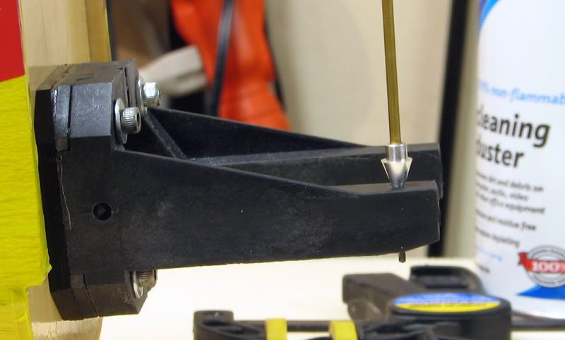
The next step is to hinge up the elevators, but I didn’t want to do that while the epoxy was wet, so I skipped ahead to the next step, mounting the engine. I didn’t want to fuss with the plane at all while the epoxy was drying, so I screwed the mount to the edge of a piece of scrap plywood and drew a line 4 15/16 inches from the rear face of the mount to simulate the firewall.
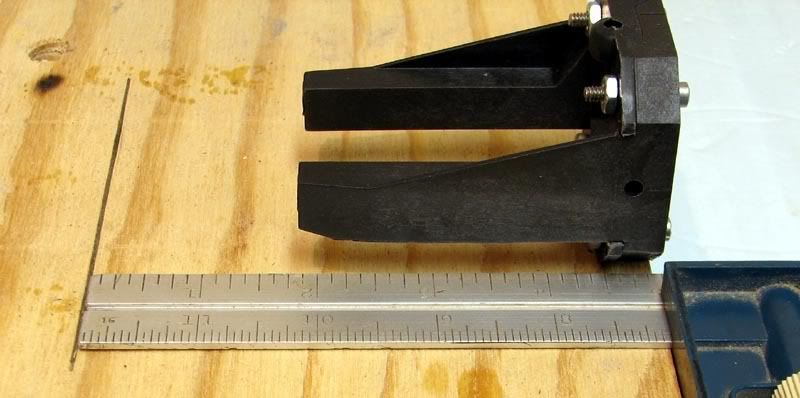
The mount is held in place by a screw passing through the nose gear bearing.
I made sure it was flush with the edge of the piece of wood.
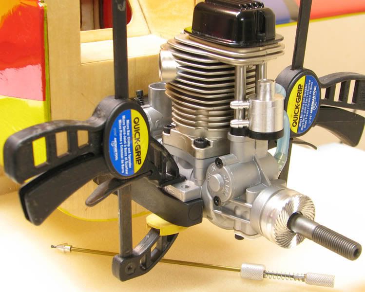
I then placed the engine on the mount and was surprised to see that even moved fully forward on the beams, it’s just a hair shy of reaching the line!
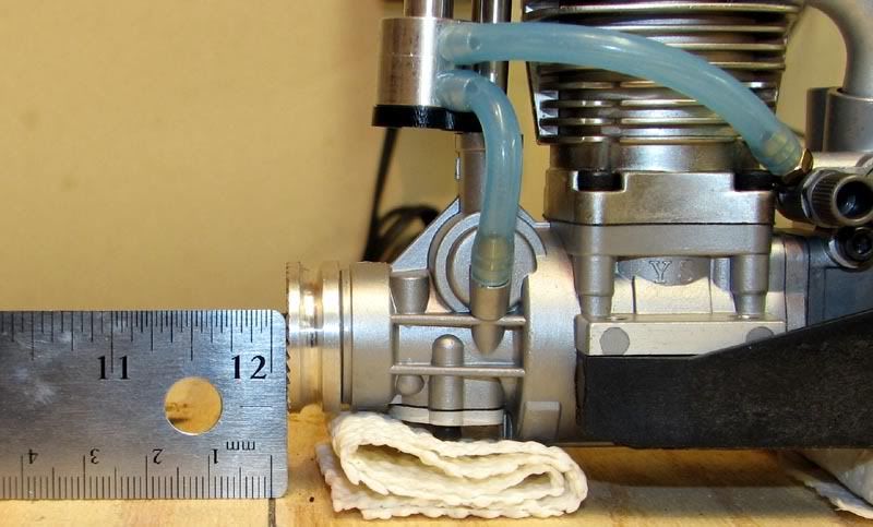
That looks to be only 1 or 2 mm’s from being a perfect fit. I’m assuming (uh oh!) that it’s safe to place the engine lugs flush with the front end of the beams. If anyone has any comments on whether or not this is safe, please chime in. Mike, if you read this, could you check with Buddy (lol) and see if he used the supplied mount? And if so, how did he remedy this situtation? It seems like the easiest thing to do would be put a spacer of 1/8 inch aircraft ply between the mount and the firewall and be done with it. If I used 1/4 inch, I could then move the engine back from the very edge of the mounting beams.
That’s it for now. Next up is to hinge the elevators and install the three servos in the tail.
I got the horizontal stab installed, and as far as I can tell it’s damn near perfect. I didn’t have to even LOOK at a piece of sandpaper and it went together exactly parallel with the wing, at least as far as my eyes can tell.
The first step was to get the wings on, which is where I ran into my first bit of real trouble with this plane. The right wing panel would not seat properly in the fuse. The first clue something was wrong was when the rear screw on the right side wouldn’t go into the fuse without cross threading. The other three were fine, so I concluded there was a spot of glue or something in the blind nut. I was wrong. Without the wing in place, the 4-40 bolt went in smooth as butter. After lots of head scratching and careful inspection, I figured out what was wrong. The opening for the front anti-rotation pin was not in the exact right location……or alternatively, the front ARP was not properly located on the wing root. Whichever it was, the solution was simple. I used a round file to open up the opening on the fuse so the wing could be nudged forward a hair. I didn’t measure, but we’re talking about less than 1 mm at the most. Here is a pic that explains it better than all those words.I relieved the front side of the indicated hole, thereby allowing the wing to nudge forward. The fit is still not perfect, and I may end up doing a little sanding in the area of the two tabs through which the bolts pass, but it goes together now, and that’s what I needed in order to get the stab installed.
After measuring to make sure the stab was centered and square, I marked along the fuse with a marker, as instructed.
I then used a soldering iron to burn through the covering along the inside of the line and pull off the center section.
It left a bunch of the pigment behind just like the black trim on the bottom of the wing. Maybe that stuff is MonoKote after all, but I’ve never seen it leave color behind on itself like that. Anyway, after a few minutes spent scraping with a fresh #11, the center was ready to be glued in.
It was a simple affair, but my hands were covered in epoxy, so I didn’t get to take any pics. Here are a couple of pics taken after the fact.
The next step is to hinge up the elevators, but I didn’t want to do that while the epoxy was wet, so I skipped ahead to the next step, mounting the engine. I didn’t want to fuss with the plane at all while the epoxy was drying, so I screwed the mount to the edge of a piece of scrap plywood and drew a line 4 15/16 inches from the rear face of the mount to simulate the firewall.
The mount is held in place by a screw passing through the nose gear bearing.
I made sure it was flush with the edge of the piece of wood.
I then placed the engine on the mount and was surprised to see that even moved fully forward on the beams, it’s just a hair shy of reaching the line!
That looks to be only 1 or 2 mm’s from being a perfect fit. I’m assuming (uh oh!) that it’s safe to place the engine lugs flush with the front end of the beams. If anyone has any comments on whether or not this is safe, please chime in. Mike, if you read this, could you check with Buddy (lol) and see if he used the supplied mount? And if so, how did he remedy this situtation? It seems like the easiest thing to do would be put a spacer of 1/8 inch aircraft ply between the mount and the firewall and be done with it. If I used 1/4 inch, I could then move the engine back from the very edge of the mounting beams.
That’s it for now. Next up is to hinge the elevators and install the three servos in the tail.
01-10-2007, 04:05 AM
#31
Senior Member

Join Date: Feb 2003
Location: Vancover,
WA
Posts: 180
Likes: 0
Received 0 Likes
on
0 Posts
Erik, as far as not being out quit far enough, I'd bet your be ok. Mine ended pretty much on the money and if you look at the pictures of mine and the red paint on the cowl, it does not quit line up with the fuselage trim, cowl could have moved back abit. Plenty of room for the cowl to back too.
The pictures are at
http://www.rcuniverse.com/forum/m_44...mpage_2/tm.htm Post 50
The pictures are at
http://www.rcuniverse.com/forum/m_44...mpage_2/tm.htm Post 50
01-12-2007, 05:55 PM
#32

My Feedback: (6)
Mike,
Do you think 9252's are overkill on the elevators? I was thinking of maybe using a standard on the rudder with a little more power like the 9252 but wasn't sure about the elevators or even if something bigger on the rudder is necessary. I would have to use 6.0 volts to get more power out of the mini's so that is one downside. The 90 oz out of the 9252's at 4.8 is a nice thought but they cost more too.
The LHS sold the only Reactors he had in stock so I told him to go ahead and order me one so it should be in next week. That Saito 82 I have sitting in a box needs a home...haha. I figure I would rather learn more on this ship before I put together the Obsession with more money in it.
ORIGINAL: MikeEast
...He used 9650's on the ailerons and 9252's on the rudder/elevator...
...He used 9650's on the ailerons and 9252's on the rudder/elevator...
01-13-2007, 03:25 PM
#33
Senior Member
Thread Starter
Join Date: Jul 2006
Location: Charlottesville,
VA
Posts: 723
Likes: 0
Received 0 Likes
on
0 Posts
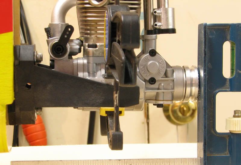
Well, after a few days of on-again off-again time in the workshop, I have a little more to report. I got the engine mounted, which first required that the template be cut out from the back page of the instruction manual and taped to the firewall.
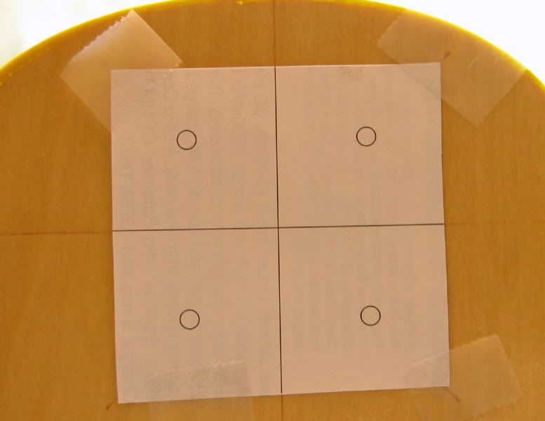
The lines on the template are lined up with the lines on the firewall depending on your powerplant of choice. For 2-stroke engines, the mount is rotated about 135 degrees from vertical, which puts a conventional muffler coming out on the bottom of the fuse. For a 4-stroke engine, it is as shown above, which puts the muffler exiting the cowl at about the 7 or 8 o’clock position when viewed from the cockpit. As others have done, I chose to use a 90 degree exhaust adaptor to get the muffler to exit on the bottom of the plane. I’ll try to get a pic of this when I get the engine mounted for good. For now, the next step was to mark and drill the holes indicated on the template.
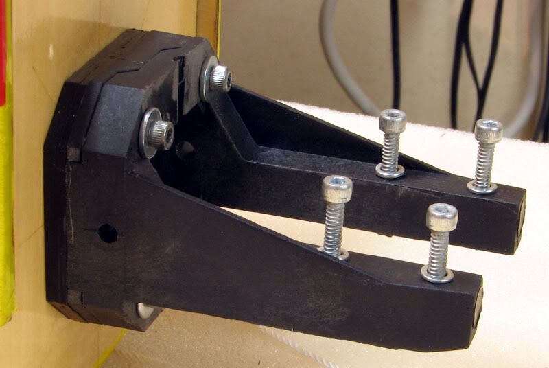
It was then a simple matter to use the 6-32 socket head cap screws to seat the blind nuts into the back side of the firewall.
I wicked in a little bit of thin CA between the edge of the blind nuts and the firewall in hopes that the nuts would stay put. I bolted the motor mount in place so I could mark and drill the necessary holes.
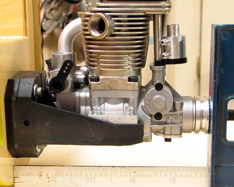
To address the spacing issue mentioned earlier, I made a 3/16 inch ply spacer, which you can see sandwiched between the firewall and the mount. I clamped the engine on the mount and measured the spacing between the firewall and thrust washer of the engine. I was able to move the engine back about 1/8 inch back from the very edge of the mounting beam, which contributes to my peace of mind, if nothing else.
In the last pic, you can see the spacer has been painted black. I was just going to coat it with epoxy, but I had some black enamel paint laying around and thought it might be easier than mixing up the epoxy and fussing with cleanup. All it took was 2 minutes with a cheap disposable foam paint brush and it was done.
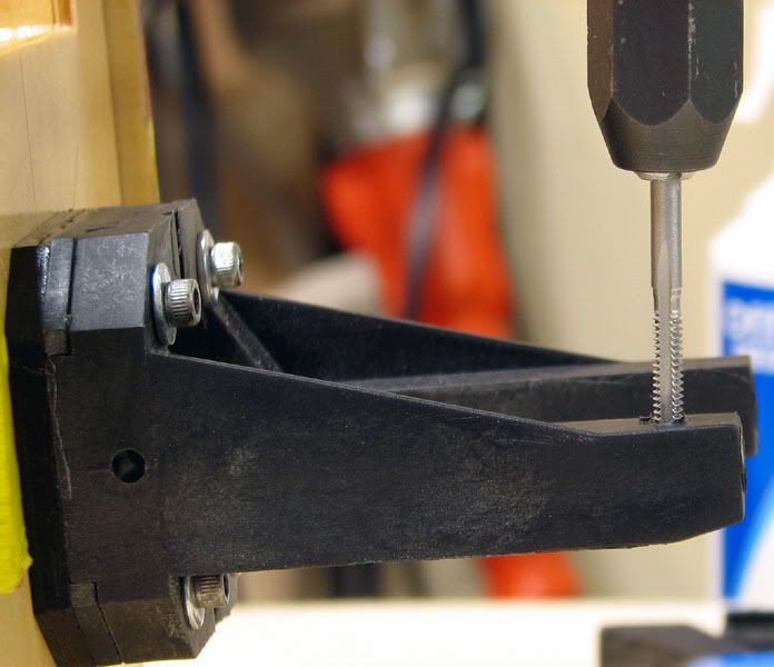
Next I used the Great Planes Dead Center device to drill the right front hole. I usually drill one hole, secure the engine, and then drill another hole. There’s less chance of me screwing up and it seems to work consistently. Speaking of the Dead Center thingy, I wouldn’t be caught dead without one. It’s the best $8 I’ve ever spent. Heck, if I had to, I’d buy one every time a built a plane. It makes a task that I used to hate one of the most simple and enjoyable ones of the entire process.
The manual simply says. “drill and tap the holes.” I guess they assume anyone assembling this plane has done this before. Fortunately, I had, so it went smoothly. I ran the tap through the first hole and then mounted up the engine with that one bolt.
After repeating the process three more times, it was done.
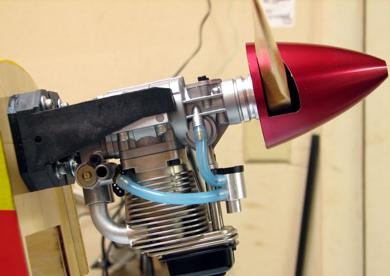
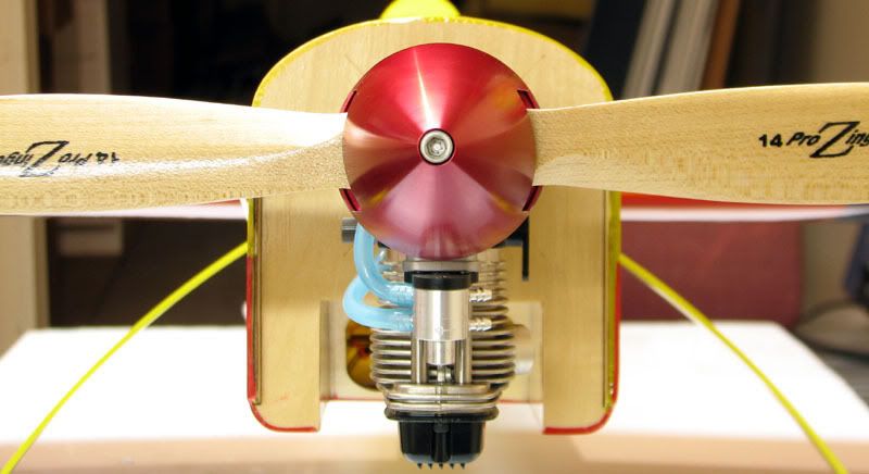
Now, I don’t know about the rest of you, but the first thing I do after getting an engine mounted for the first time, is bolt up a prop and flip a few times. This case was no different.
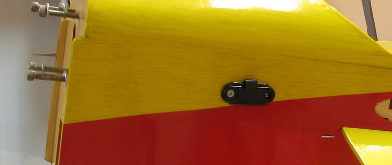
Next it was time to mount the switch and charge jack. The manual directs you to mount the switch on the side of the fuse under the wing, which not only seems terribly inconvenient, but would interfere with my plan to mount the fuel tank in that area. Instead, I used a scrap piece of 1/16 inch balsa to make a tray, hardened it with thin CA and mounted the switch to it. I then glued it in place right in front of the landing gear mount.
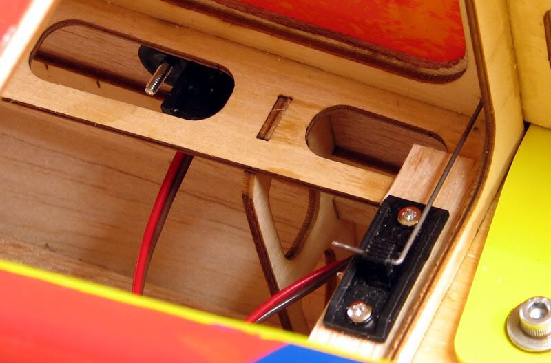
I used a scrap piece of music wire to make a little pushrod to actuate the switch. If you look below the switch you can see the Ernst charge receptacle mounted beneath and forward of it. I said a few choice words while getting my fat fingers in the tight space, but finally got it in. Here is shot showing the “high-tech” pushrod.
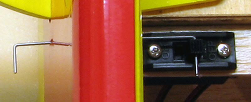
And here is what they both look like from outside the fuse.
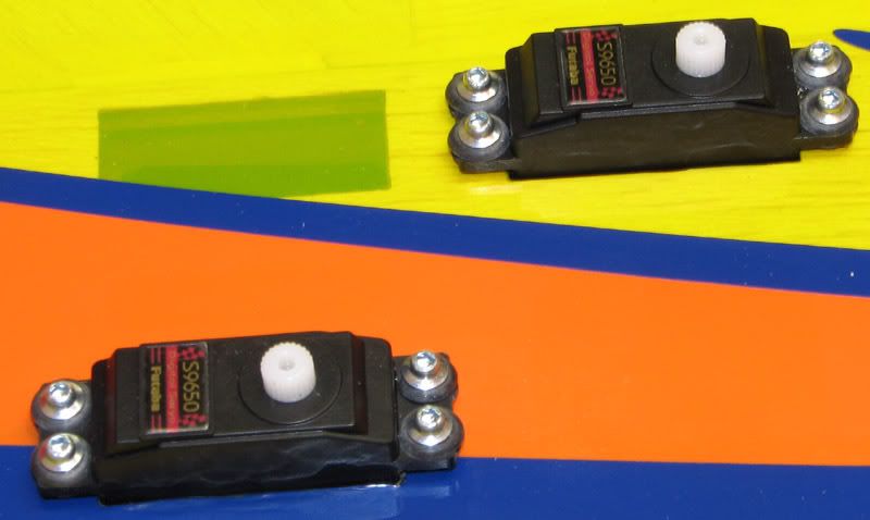
Next were the servos for the tail. I had skipped over this step because they hadn’t arrived yet. I was originally going to use the same servos as in the wing, Hitec 5245s, but after the time it took to modify the wing openings, I decided to go ahead and get the servos for which the cutouts were made. The Futaba 9650s dropped right in with no mods necessary.
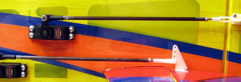
As with the aileron linkage, the supplied hardware was used. I did decide, however, to make up some carbon fiber pushrods for the tail feathers. I used JB Weld to secure short lengths of 2-56 all-thread into .157 OD carbon tube. One end gets a Dubro swivel link and the other end uses the supplied nylon clevis. The main reason I did this was because there was some slight binding at extreme control throws and I wanted to use the swivel links to remedy this. The carbon fiber tubes weren’t necessary, but I had them in my stash and figured what the heck. I’ll try to get pics of those up soon.
The lines on the template are lined up with the lines on the firewall depending on your powerplant of choice. For 2-stroke engines, the mount is rotated about 135 degrees from vertical, which puts a conventional muffler coming out on the bottom of the fuse. For a 4-stroke engine, it is as shown above, which puts the muffler exiting the cowl at about the 7 or 8 o’clock position when viewed from the cockpit. As others have done, I chose to use a 90 degree exhaust adaptor to get the muffler to exit on the bottom of the plane. I’ll try to get a pic of this when I get the engine mounted for good. For now, the next step was to mark and drill the holes indicated on the template.
It was then a simple matter to use the 6-32 socket head cap screws to seat the blind nuts into the back side of the firewall.
I wicked in a little bit of thin CA between the edge of the blind nuts and the firewall in hopes that the nuts would stay put. I bolted the motor mount in place so I could mark and drill the necessary holes.
To address the spacing issue mentioned earlier, I made a 3/16 inch ply spacer, which you can see sandwiched between the firewall and the mount. I clamped the engine on the mount and measured the spacing between the firewall and thrust washer of the engine. I was able to move the engine back about 1/8 inch back from the very edge of the mounting beam, which contributes to my peace of mind, if nothing else.
In the last pic, you can see the spacer has been painted black. I was just going to coat it with epoxy, but I had some black enamel paint laying around and thought it might be easier than mixing up the epoxy and fussing with cleanup. All it took was 2 minutes with a cheap disposable foam paint brush and it was done.
Next I used the Great Planes Dead Center device to drill the right front hole. I usually drill one hole, secure the engine, and then drill another hole. There’s less chance of me screwing up and it seems to work consistently. Speaking of the Dead Center thingy, I wouldn’t be caught dead without one. It’s the best $8 I’ve ever spent. Heck, if I had to, I’d buy one every time a built a plane. It makes a task that I used to hate one of the most simple and enjoyable ones of the entire process.
The manual simply says. “drill and tap the holes.” I guess they assume anyone assembling this plane has done this before. Fortunately, I had, so it went smoothly. I ran the tap through the first hole and then mounted up the engine with that one bolt.
After repeating the process three more times, it was done.
Now, I don’t know about the rest of you, but the first thing I do after getting an engine mounted for the first time, is bolt up a prop and flip a few times. This case was no different.
Next it was time to mount the switch and charge jack. The manual directs you to mount the switch on the side of the fuse under the wing, which not only seems terribly inconvenient, but would interfere with my plan to mount the fuel tank in that area. Instead, I used a scrap piece of 1/16 inch balsa to make a tray, hardened it with thin CA and mounted the switch to it. I then glued it in place right in front of the landing gear mount.
I used a scrap piece of music wire to make a little pushrod to actuate the switch. If you look below the switch you can see the Ernst charge receptacle mounted beneath and forward of it. I said a few choice words while getting my fat fingers in the tight space, but finally got it in. Here is shot showing the “high-tech” pushrod.
And here is what they both look like from outside the fuse.
Next were the servos for the tail. I had skipped over this step because they hadn’t arrived yet. I was originally going to use the same servos as in the wing, Hitec 5245s, but after the time it took to modify the wing openings, I decided to go ahead and get the servos for which the cutouts were made. The Futaba 9650s dropped right in with no mods necessary.
As with the aileron linkage, the supplied hardware was used. I did decide, however, to make up some carbon fiber pushrods for the tail feathers. I used JB Weld to secure short lengths of 2-56 all-thread into .157 OD carbon tube. One end gets a Dubro swivel link and the other end uses the supplied nylon clevis. The main reason I did this was because there was some slight binding at extreme control throws and I wanted to use the swivel links to remedy this. The carbon fiber tubes weren’t necessary, but I had them in my stash and figured what the heck. I’ll try to get pics of those up soon.
01-15-2007, 02:39 AM
#34


Join Date: Jul 2002
Location: Tacoma,
WA
Posts: 5,037
Likes: 0
Received 0 Likes
on
0 Posts
Erik, GOTTA love that picture with the red spinner! Did you use the Paint program to insert the cool arrow in your photo???
Thanks,
Ernie
Thanks,
Ernie
01-15-2007, 08:14 AM
#35
Senior Member
Thread Starter
Join Date: Jul 2006
Location: Charlottesville,
VA
Posts: 723
Likes: 0
Received 0 Likes
on
0 Posts
Hi Ernie. The spinner pics turned out well; I really like them too. The arrow was added in Photoshop, but I think Paint has that capability as well.
Erik
The arrow was added in Photoshop, but I think Paint has that capability as well.Erik
 01-20-2007, 08:09 AM
#37

ORIGINAL: rustypep
Mike,
Do you think 9252's are overkill on the elevators? I was thinking of maybe using a standard on the rudder with a little more power like the 9252 but wasn't sure about the elevators or even if something bigger on the rudder is necessary. I would have to use 6.0 volts to get more power out of the mini's so that is one downside. The 90 oz out of the 9252's at 4.8 is a nice thought but they cost more too.
The LHS sold the only Reactors he had in stock so I told him to go ahead and order me one so it should be in next week. That Saito 82 I have sitting in a box needs a home...haha. I figure I would rather learn more on this ship before I put together the Obsession with more money in it.
ORIGINAL: MikeEast
...He used 9650's on the ailerons and 9252's on the rudder/elevator...
...He used 9650's on the ailerons and 9252's on the rudder/elevator...
I think they are way more than you NEED. I think a nice metal gear servo about ~75oz is probably more than enough. A standard will work I have no doubt, but it just wont be as crisp. I think a Hitec 6635 would be plenty, but for just a couple of $$ more the 5645 would be awesome.. Thats roughly a $30 savings over a 9252.
01-20-2007, 03:28 PM
#38
Join Date: Jul 2002
Location: Tacoma,
WA
Posts: 5,037
Likes: 0
Received 0 Likes
on
0 Posts
Hey Mike, Erik, and all, we talk so much about the torque and stall aspects of the servos, but what about the speed. Just how much difference in speed is really noticable? For example of the 6635 and 5645 servos that Mike mentioned, the less powerful and expensive 6635 is actually quite a bit faster. (.21 vs .15)
I love my standard Hitec 475 servos that weigh only 1.4 oz but the speed is only .23 sec at 4.8 volts. So how much am I missing out (mostly sport and aerobatic, some 3D) over servos that are as fast as .15 sec?
Thanks,
Ernie
I love my standard Hitec 475 servos that weigh only 1.4 oz but the speed is only .23 sec at 4.8 volts. So how much am I missing out (mostly sport and aerobatic, some 3D) over servos that are as fast as .15 sec?
Thanks,
Ernie
01-20-2007, 04:36 PM
#39
Senior Member
Thread Starter
Join Date: Jul 2006
Location: Charlottesville,
VA
Posts: 723
Likes: 0
Received 0 Likes
on
0 Posts
Ernie,
This is just my two cents.....I think for the average sport pilot, the difference between .23 seconds and .15 seconds is hardly noticeable. I'm almost certain I wouldn't be able to tell the difference...at least not right now, anyway.
This Reactor is only the second plane in which I have ever used non-standard servos. The first plane is one I finished just a couple months ago (Extreme Flight Edge) and I might have 8 or 10 flights on it, so I really am in no position to compare. I'm really working to move my flying skills to the next level and have put better servos in these planes in hopes that I would "grow into them," so to speak. My suspicion is that after flying planes equipped with better servos, I'd be able to tell the difference very quickly. It's sort of like that old saying, "You never miss the water until the well runs dry."
01-21-2007, 01:49 AM
#40
My Feedback: (6)
I was already thinking 6635's on everything. The only one I was considering changing was the rudder and the 5645 is a nice thought so thanks. I guess the 5625 would work well too on a plane this size. I meant to say a more standard size digital with more torque (like the 5645). My only concern there is the 2.11 oz weight which is about double the weight of the 5645 (1.11oz). If I need tail weight thought, that would do the trick. It will be interesting to see how everyone does on balancing with the 6635's. I want metal gears and the programability of the hitecs is also nice. Thanks for the response and I haven't had much time to read up lately either. I got my Reactor and I am watching this tread with interest.
ORIGINAL: MikeEast
Sorry it took me so long to respond. I have been working and not had much time to read up.
I think they are way more than you NEED. I think a nice metal gear servo about ~75oz is probably more than enough. A standard will work I have no doubt, but it just wont be as crisp. I think a Hitec 6635 would be plenty, but for just a couple of $$ more the 5645 would be awesome.. Thats roughly a $30 savings over a 9252.
01-21-2007, 01:15 PM
#41
Senior Member
Join Date: Mar 2003
Location: Vancouver,
BC, CANADA
Posts: 309
Likes: 0
Received 0 Likes
on
0 Posts
ORIGINAL: JustErik
Ernie,
This is just my two cents.....I think for the average sport pilot, the difference between .23 seconds and .15 seconds is hardly noticeable. I'm almost certain I wouldn't be able to tell the difference...at least not right now, anyway.
This Reactor is only the second plane in which I have ever used non-standard servos. The first plane is one I finished just a couple months ago (Extreme Flight Edge) and I might have 8 or 10 flights on it, so I really am in no position to compare. I'm really working to move my flying skills to the next level and have put better servos in these planes in hopes that I would "grow into them," so to speak. My suspicion is that after flying planes equipped with better servos, I'd be able to tell the difference very quickly. It's sort of like that old saying, "You never miss the water until the well runs dry."
What is more important, to me at least, is how well the servos centre. A lot of the cheaper servos, particularily the non-digitals, have very poor centering. This makes trimming and any precision manuvers very difficult.
Malcolm
01-29-2007, 08:42 PM
#42
Junior Member
Join Date: Sep 2004
Location: Anchorage,
AK
Posts: 6
Likes: 0
Received 0 Likes
on
0 Posts
Does anyone have pictures of an OS .46 or .55AX mounted on one of these? I'm curious whether/how the muffler fits in the cutout below the firewall. Also, what is the mounting depth available for the wing servos? I too am a big fan of the Hitec HS-475HB servos - their specs @ 6V are 76 oz/in and .18 sec transit time. I just don't know if the wing is deep enough to take them.
TIA - great thread!
TIA - great thread!
 01-30-2007, 08:11 AM
#44
Senior Member
Thread Starter
Join Date: Jul 2006
Location: Charlottesville,
VA
Posts: 723
Likes: 0
Received 0 Likes
on
0 Posts
ORIGINAL: Kostas1
Good worl so far Erik!
Good worl so far Erik!
Erik
01-30-2007, 10:32 PM
#45
Senior Member
Thread Starter
Join Date: Jul 2006
Location: Charlottesville,
VA
Posts: 723
Likes: 0
Received 0 Likes
on
0 Posts
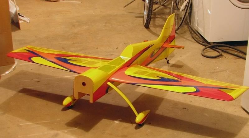
Well, the plane is done and ready to fly. It took a bit longer than I anticipated, but nevertheless, it’s completed. I think I left off with the tail servos and the whole CF pushrod subject. Here are the pushrods installed and ready for action. They are not any lighter than the stock ones, but they are stiffer and the swivel link on the servo arms allows for full movement with no binding.
I got the engine plumbed with the help of these.
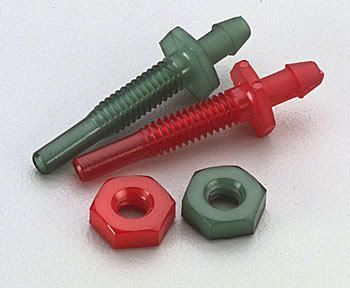
They are Fourmost Bulkhead Fittings and allow you to pass fuel through a firewall or fuse side without having to worry about fuel seeping in around the edges of the hole. As described in the instruction manual, I assembled the tank with a three-line option. However, instead of using fuel dots to access both the pressure and feed line, as is typically done with YS installations, I installed two Fourmost Bulkhead Fittings in the side of the fuse. One of these goes to the dedicated fill/drain line in the tank and the other goes to a T-fitting installed in the pressure line, downstream from the check valve, which is what maintains the pressure in the tank. As shown in the diagram below, this plumbing eliminates one of the T’s from the system and provides for an uninterrupted feed line to the engine. Here is how it all goes together.
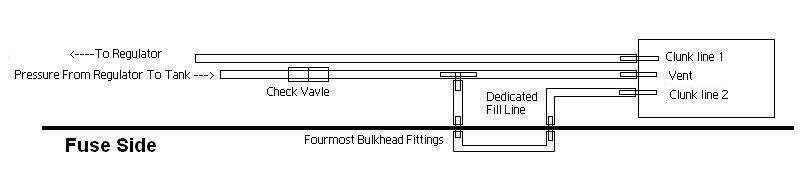
In practice, the two bulkhead fittings use a "jumper" piece of fuel line to join them together, effectively pressurizing the tank via both the vent line and the fill/drain line. At the end of a flight, one simply pinches the jumper line shut and pulls it off the bulkhead fitting tapped into the pressure line. This vents the pressure in the tank without spraying fuel everywhere. Then, you can plug your fuel jug feed line into the jumper line and fill or drain the tank. On the plane, the actual fittings are much closer together than depicted in the diagram. The jumper line is only about 1.5 inches long.
To me, this setup seems easier than dots because there are no plugs to remove (and lose!), no lines to feed through the fuse side and only one connection to handle on the plane. I imagine that’s a lot more detail than anyone wanted or needed on this subject.
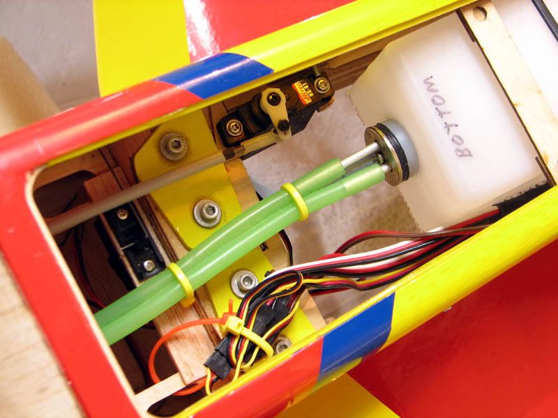
Here is a pic of the placement of the throttle servo, fuel tank and power switch. There’s nothing really out of the ordinary here.
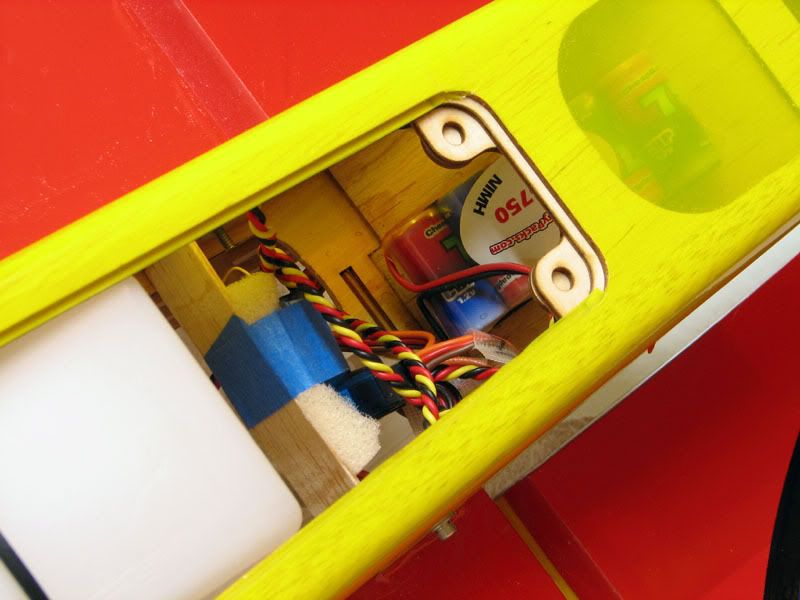
Right behind the tank, I mounted the receiver and battery. I know it’s generally considered bad to put the battery behind the receiver, but I needed to do that for balance reasons. As it is, I may end up having to add weight to the tail or perhaps put a larger battery in.
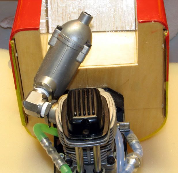
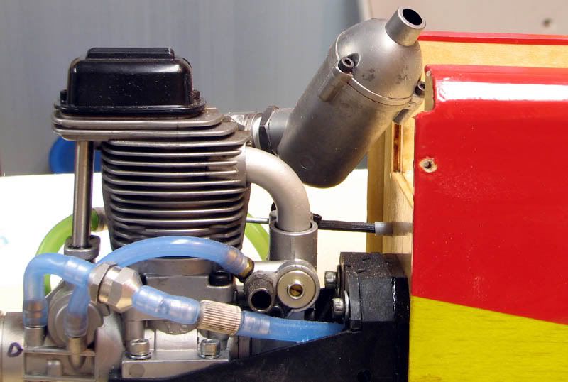
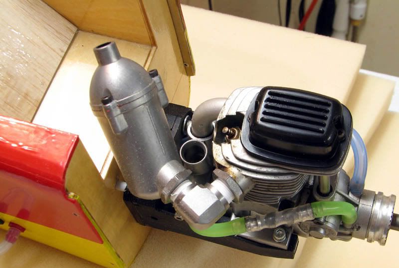
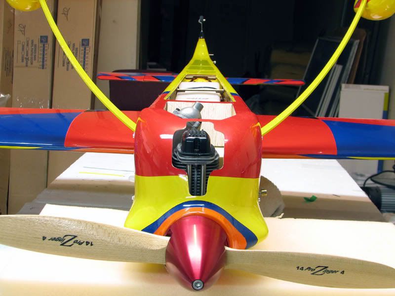
Here are a few pics of the engine installation. You can see the 90 degree adaptor installed and how it very neatly keeps the entire exhaust system inside the cowl.
Here is a front view of the plane with the cowl installed. Before anyone gives me a hard time for the hacked up cowl opening, let me say this is the first one of these I ever did. I wanted to err on the side of caution, so I made it larger than was probably needed.
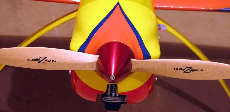
Here is an even less flattering angle. I forgot to consider the fact that the right thrust of the firewall means the engine does not line up perfectly with the cowl, so I ended up with the opening being off center.
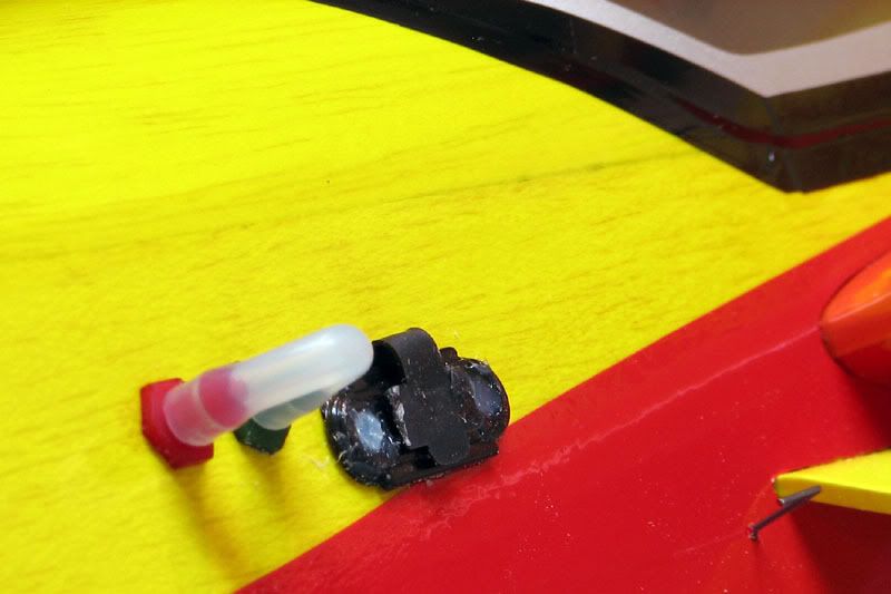
Here is a pic of the left side of the plane showing the placement of the charge jack, fuel fittings and power switch.
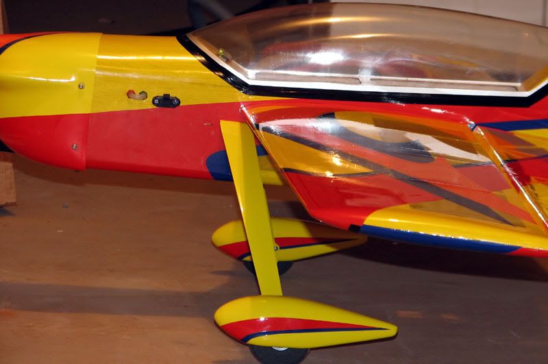
Here is the same side from farther back.
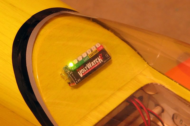
I installed a VoltWatch in the canopy area just because I had one sitting around and had never taken the opportunity to try it out. I drilled a small hole so the wire could make its way to the receiver without showing in the cockpit.
Here is the canopy area from a little farther back.
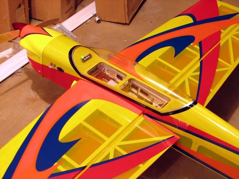
The canopy is held on with black vinyl that I got from a local sign shop. I cut it into strips about 3/8 of an inch wide and it easily stretched around the curves. It’s removable should I ever need to get in there and it didn’t require using any screws to mar the clean lines of the plane.
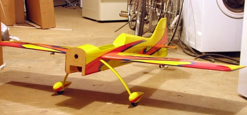
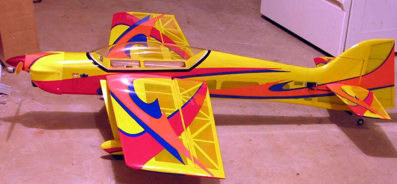
Here is one last pic of the side of the plane.
I have yet to put any decals on it. To be honest, I’m not sure I even want to.
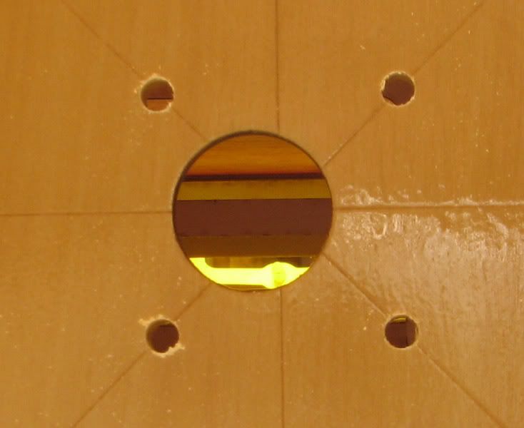
The all up weight as shown in these pics is 5 pounds, 10 ounces or 5.63 pounds. I suppose this will be fine, but I was really hoping to come in at 5.5 or less. I did my best to cut out weight. I removed all the lite ply “grid” in the radio compartment. I was very careful about how much glue I used. My servo selection was about as light as possible to still maintain positive control with a good margin of safety. I even used a 750 maH NiMH battery pack. I did pick up about 1.5 ounces with the aluminum spinner, so maybe that accounts for most of the difference. I almost wasn’t going to post the following pic, but since I’m discussing weight, I might as well confess. I didn’t use the bottom hatch to seal up the fuse.
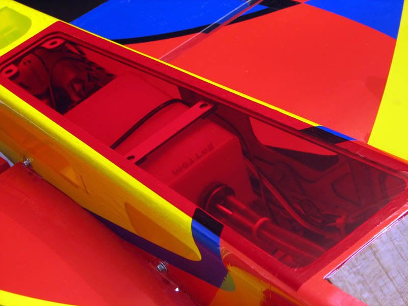
Primarily, I was concerned about how well it would keep glow residue out. After weighing it, I also realized I could shave another 2/3 of an ounce or so. I used it as a template to cut a piece of transparent red MonoKote, which is what you see in the above picture. Even with this, I couldn’t get the weight down to 5.5 pounds. I’m sure it will be fine however. I bet I wouldn’t even be able to tell the difference if it were suddenly 2 ounces lighter.
The sad part is that I probably won’t get to maiden the thing for several weeks. I’m a wimp when it comes to cold weather and it’s just been brutal here lately. Fortunately, I have another project on deck to keep me occupied. I’ll be starting a MoJo 60 kit soon, which will take me considerably longer than the Reactor did. Heck, it might be Spring before that one is done.
I got the engine plumbed with the help of these.
They are Fourmost Bulkhead Fittings and allow you to pass fuel through a firewall or fuse side without having to worry about fuel seeping in around the edges of the hole. As described in the instruction manual, I assembled the tank with a three-line option. However, instead of using fuel dots to access both the pressure and feed line, as is typically done with YS installations, I installed two Fourmost Bulkhead Fittings in the side of the fuse. One of these goes to the dedicated fill/drain line in the tank and the other goes to a T-fitting installed in the pressure line, downstream from the check valve, which is what maintains the pressure in the tank. As shown in the diagram below, this plumbing eliminates one of the T’s from the system and provides for an uninterrupted feed line to the engine. Here is how it all goes together.
In practice, the two bulkhead fittings use a "jumper" piece of fuel line to join them together, effectively pressurizing the tank via both the vent line and the fill/drain line. At the end of a flight, one simply pinches the jumper line shut and pulls it off the bulkhead fitting tapped into the pressure line. This vents the pressure in the tank without spraying fuel everywhere. Then, you can plug your fuel jug feed line into the jumper line and fill or drain the tank. On the plane, the actual fittings are much closer together than depicted in the diagram. The jumper line is only about 1.5 inches long.
To me, this setup seems easier than dots because there are no plugs to remove (and lose!), no lines to feed through the fuse side and only one connection to handle on the plane. I imagine that’s a lot more detail than anyone wanted or needed on this subject.
Here is a pic of the placement of the throttle servo, fuel tank and power switch. There’s nothing really out of the ordinary here.
Right behind the tank, I mounted the receiver and battery. I know it’s generally considered bad to put the battery behind the receiver, but I needed to do that for balance reasons. As it is, I may end up having to add weight to the tail or perhaps put a larger battery in.
Here are a few pics of the engine installation. You can see the 90 degree adaptor installed and how it very neatly keeps the entire exhaust system inside the cowl.
Here is a front view of the plane with the cowl installed. Before anyone gives me a hard time for the hacked up cowl opening, let me say this is the first one of these I ever did.
I wanted to err on the side of caution, so I made it larger than was probably needed.Here is an even less flattering angle. I forgot to consider the fact that the right thrust of the firewall means the engine does not line up perfectly with the cowl, so I ended up with the opening being off center.
Here is a pic of the left side of the plane showing the placement of the charge jack, fuel fittings and power switch.
Here is the same side from farther back.
I installed a VoltWatch in the canopy area just because I had one sitting around and had never taken the opportunity to try it out. I drilled a small hole so the wire could make its way to the receiver without showing in the cockpit.
Here is the canopy area from a little farther back.
The canopy is held on with black vinyl that I got from a local sign shop. I cut it into strips about 3/8 of an inch wide and it easily stretched around the curves. It’s removable should I ever need to get in there and it didn’t require using any screws to mar the clean lines of the plane.
Here is one last pic of the side of the plane.
I have yet to put any decals on it. To be honest, I’m not sure I even want to.
The all up weight as shown in these pics is 5 pounds, 10 ounces or 5.63 pounds. I suppose this will be fine, but I was really hoping to come in at 5.5 or less. I did my best to cut out weight. I removed all the lite ply “grid” in the radio compartment. I was very careful about how much glue I used. My servo selection was about as light as possible to still maintain positive control with a good margin of safety. I even used a 750 maH NiMH battery pack. I did pick up about 1.5 ounces with the aluminum spinner, so maybe that accounts for most of the difference. I almost wasn’t going to post the following pic, but since I’m discussing weight, I might as well confess. I didn’t use the bottom hatch to seal up the fuse.
Primarily, I was concerned about how well it would keep glow residue out. After weighing it, I also realized I could shave another 2/3 of an ounce or so. I used it as a template to cut a piece of transparent red MonoKote, which is what you see in the above picture. Even with this, I couldn’t get the weight down to 5.5 pounds. I’m sure it will be fine however. I bet I wouldn’t even be able to tell the difference if it were suddenly 2 ounces lighter.
The sad part is that I probably won’t get to maiden the thing for several weeks. I’m a wimp when it comes to cold weather and it’s just been brutal here lately. Fortunately, I have another project on deck to keep me occupied. I’ll be starting a MoJo 60 kit soon, which will take me considerably longer than the Reactor did. Heck, it might be Spring before that one is done.
01-30-2007, 11:39 PM
#46
Senior Member
Join Date: Jun 2005
Location: -, ARGENTINA
Posts: 163
Likes: 0
Received 0 Likes
on
0 Posts
Hello JustErik, excellent work in the model and the forum!
When you installed the motor is the YS 63S, but later in the end 63FZ appears the YS.
This is correct?
Greetings from Argentina.
PS: also I have a YS 63S and I like the Reactor! still I do not have information of how it flies.
When you installed the motor is the YS 63S, but later in the end 63FZ appears the YS.
This is correct?
Greetings from Argentina.
PS: also I have a YS 63S and I like the Reactor! still I do not have information of how it flies.
01-31-2007, 08:00 AM
#47
Senior Member
Thread Starter
Join Date: Jul 2006
Location: Charlottesville,
VA
Posts: 723
Likes: 0
Received 0 Likes
on
0 Posts
Good eye, Guillermito, and thanks! When I set up the motor mount and cowl spacing, I used a new 63S from my stash because the engine destined for the Reactor had not yet arrived. I bought one used from a guy on another forum and didn't have it in hand at the time. Shortly after I posted the pics, the correct engine arrived and I was able to swap them out. Oh, and in case you haven't seen it, there are some flight reports of the Reactor on page 5 of this thread.
Erik
When I set up the motor mount and cowl spacing, I used a new 63S from my stash because the engine destined for the Reactor had not yet arrived. I bought one used from a guy on another forum and didn't have it in hand at the time. Shortly after I posted the pics, the correct engine arrived and I was able to swap them out. Oh, and in case you haven't seen it, there are some flight reports of the Reactor on page 5 of this thread.Erik
01-31-2007, 11:23 AM
#48
Senior Member
Join Date: Mar 2003
Location: Vancouver,
BC, CANADA
Posts: 309
Likes: 0
Received 0 Likes
on
0 Posts
Excellent build thread JustErik, I'm looking forward to hearing how it flies. I don't think you should be too disappointed in the final weight - I was considering buying the Showtime 50, which is a similar size, but they are coming in a lot heavier than the Reactor.
I'm only about 1/3 of the way through my Reactor build. I have found similar minor issues as you. As you said, the covering is really strange, not like any Monokote I have ever used. Overall, so far I am very pleased with the plane. I will be powering mine with an OS 55 AX. I wanted to go electric, but it would have cost me around $700 (with 2 battery packs) versus $170 for the 2 stroke in Canada.
Malcolm
01-31-2007, 11:33 AM
#49
Senior Member
Thread Starter
Join Date: Jul 2006
Location: Charlottesville,
VA
Posts: 723
Likes: 0
Received 0 Likes
on
0 Posts
Thanks Malcom. The Reactor should be insane with a 55 AX on the nose! It ought to be a heck of a combination. What are you doing for a muffler? I imagine the stock muffler would nestle very neatly in the cutout behind the engine. I wonder if a pitts style would fit within the cowl...or even if it would be necessary? What size prop do you anticipate running? I've read that the 55 AX will happily swing an APC 13 x 4W at well over 11,000 RPM. That thing should go up like the space shuttle! Please take some pics so we can see how it comes together.
Erik
The Reactor should be insane with a 55 AX on the nose! It ought to be a heck of a combination. What are you doing for a muffler? I imagine the stock muffler would nestle very neatly in the cutout behind the engine. I wonder if a pitts style would fit within the cowl...or even if it would be necessary? What size prop do you anticipate running? I've read that the 55 AX will happily swing an APC 13 x 4W at well over 11,000 RPM. That thing should go up like the space shuttle! Please take some pics so we can see how it comes together.Erik
01-31-2007, 11:56 AM
#50
My Feedback: (157)

Join Date: Mar 2002
Location: Kirkland, WA
Posts: 291
Likes: 0
Received 0 Likes
on
0 Posts
Great job on the build thread Erik! I immediately noticed-- and was suprised-- that you had removed part of the plywood "grid" (in the radio compartment). I really don't think you should worry so much about the weight, you are going to be amazed at how quickly the YS pulls this airframe towards the heavens! Best of luck with the maiden!
One thing that I forgot to address in the other thread-- the magnetic hatch-cover. First of all, for those who have not played with the hatch, there is absolutely NO danger that this thing is going to come off while flying (unless all six magnets come unglued)! That being said, it is also very difficult to remove when you want to! The biggest problem is that there is no "handle" to pull the hatch up with. I drilled two small holes (1/16") in the rear of the hatch and looped a piece of thread through them (tie the thread in a loop inside the hatch). This make a hatch removal effortless and adds almost no weight or visible change.
One thing that I forgot to address in the other thread-- the magnetic hatch-cover. First of all, for those who have not played with the hatch, there is absolutely NO danger that this thing is going to come off while flying (unless all six magnets come unglued)! That being said, it is also very difficult to remove when you want to! The biggest problem is that there is no "handle" to pull the hatch up with. I drilled two small holes (1/16") in the rear of the hatch and looped a piece of thread through them (tie the thread in a loop inside the hatch). This make a hatch removal effortless and adds almost no weight or visible change.