


SPAD Twist-VSF
 03-10-2009, 04:00 PM
#1
Member
Thread Starter

Join Date: Oct 2004
Location: Lawton, OK
Posts: 53
Likes: 0
Received 0 Likes
on
0 Posts
I used a V Shaped Fuse in an effort to keep the rear weight down (less glue) and make the building of the turtle deck easier for my SPAD version of a Twist 40.
Benefits: The less complicated and lighter tail structure allowed me to place the elevator and rudder servos closer to the back with straight connections to the control horns. There are two formers in the tail and it is less "twisty" back there. It also helps to avoid the long nose look - I did not need to add any weight to the nose for balance even with the short nose to CG distance. I had planned to put the battery up next to the firewall, but that wasn't necessary after all. I think anybody building a plane with a turtle deck could use this fuse technique.
Here is a pattern for one side of the fuse. I traced around an un-assembled Balsa Twist 40. I added a little extra to the top of the turtle deck area to account for the curve over the top.
[link=http://www.frostracing.com/RC/07aspadtwist/800x600/img_0312.jpg]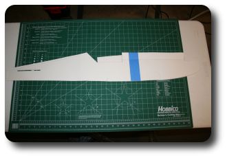 [/link]
Next I created a duplicate fuse pattern and then taped the two patterns together along the turtle deck area. Note the V shape.
[link=http://www.frostracing.com/RC/07aspadtwist/800x600/img_0315.jpg]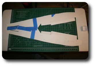 [/link]
Here are a few images of the pattern folded in the sort-of shape of the fuse. (I don't have any construction photos - these photos of the patterns where taken after I was done with the plane and I knew that the VSF idea worked)
[link=http://www.frostracing.com/RC/07aspadtwist/800x600/img_0318.jpg]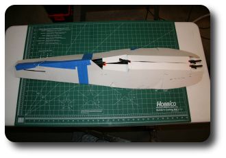 [/link]
[link=http://www.frostracing.com/RC/07aspadtwist/800x600/img_0319.jpg]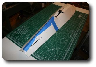 [/link]
[link=http://www.frostracing.com/RC/07aspadtwist/800x600/img_0320.jpg]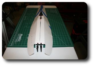 [/link]
I aligned the fuse pattern with the flutes of the corro length wise and cut out the the V shape from the corro. I had to cut the inner skin of the flutes in the turtle deck area to allow the corro to curve forming a smooth turtle deck. I started with the center flute and worked my way outwards until the curve of the turtle deck looked right.
Here is the resulting plane. There is a seam in the center of the top of the fuse from the firewall to the turtle deck. It has 6 #4 screws thru PVC plus 2 mil corro CA'ed to the inside holding the front together. The seam is covered with yellow contact paper. There are no seams in the side of the fuse. The flutes in the bottom fuse pieces of corro run cross ways.
The plane weighs 5 lbs 12.6 oz. I have a Saito .82 engine with a APC 14x4W prop. I used a huge 16oz tank to get more flight time with the .82 - it is a thirsty engine.
See more pics and instructions here: [link=http://spadworld.net/forum/viewtopic.php?t=14425]SPAD Twist-VSF[/link]
[link=http://www.frostracing.com/RC/07aspadtwist/800x600/img_0288.jpg]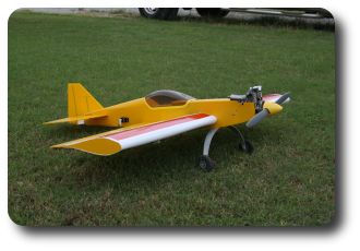 [/link]
[link=http://www.frostracing.com/RC/07aspadtwist/800x600/img_0282.jpg]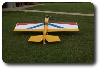 [/link]
[link=http://www.frostracing.com/RC/07aspadtwist/800x600/img_0283.jpg]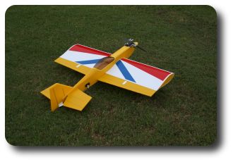 [/link]
[link=http://www.frostracing.com/RC/07aspadtwist/800x600/img_0290.jpg]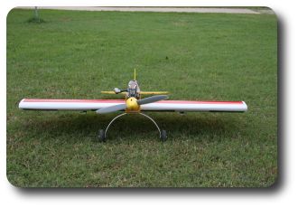 [/link]
[link=http://www.frostracing.com/RC/07aspadtwist/800x600/img_0323.jpg]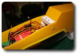 [/link]
[link=http://www.frostracing.com/RC/07aspadtwist/800x600/img_0324.jpg]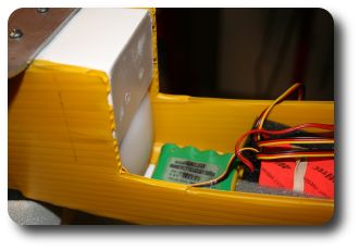 [/link]
[link=http://www.frostracing.com/RC/07aspadtwist/800x600/img_0327.jpg]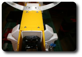 [/link]
[link=http://www.frostracing.com/RC/07aspadtwist/800x600/img_0333.jpg]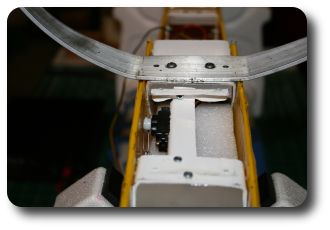 [/link]
Benefits: The less complicated and lighter tail structure allowed me to place the elevator and rudder servos closer to the back with straight connections to the control horns. There are two formers in the tail and it is less "twisty" back there. It also helps to avoid the long nose look - I did not need to add any weight to the nose for balance even with the short nose to CG distance. I had planned to put the battery up next to the firewall, but that wasn't necessary after all. I think anybody building a plane with a turtle deck could use this fuse technique.
Here is a pattern for one side of the fuse. I traced around an un-assembled Balsa Twist 40. I added a little extra to the top of the turtle deck area to account for the curve over the top.
[link=http://www.frostracing.com/RC/07aspadtwist/800x600/img_0312.jpg]
[/link]Next I created a duplicate fuse pattern and then taped the two patterns together along the turtle deck area. Note the V shape.
[link=http://www.frostracing.com/RC/07aspadtwist/800x600/img_0315.jpg]
[/link]Here are a few images of the pattern folded in the sort-of shape of the fuse. (I don't have any construction photos - these photos of the patterns where taken after I was done with the plane and I knew that the VSF idea worked)
[link=http://www.frostracing.com/RC/07aspadtwist/800x600/img_0318.jpg]
[/link][link=http://www.frostracing.com/RC/07aspadtwist/800x600/img_0319.jpg]
[/link][link=http://www.frostracing.com/RC/07aspadtwist/800x600/img_0320.jpg]
[/link]I aligned the fuse pattern with the flutes of the corro length wise and cut out the the V shape from the corro. I had to cut the inner skin of the flutes in the turtle deck area to allow the corro to curve forming a smooth turtle deck. I started with the center flute and worked my way outwards until the curve of the turtle deck looked right.
Here is the resulting plane. There is a seam in the center of the top of the fuse from the firewall to the turtle deck. It has 6 #4 screws thru PVC plus 2 mil corro CA'ed to the inside holding the front together. The seam is covered with yellow contact paper. There are no seams in the side of the fuse. The flutes in the bottom fuse pieces of corro run cross ways.
The plane weighs 5 lbs 12.6 oz. I have a Saito .82 engine with a APC 14x4W prop. I used a huge 16oz tank to get more flight time with the .82 - it is a thirsty engine.
See more pics and instructions here: [link=http://spadworld.net/forum/viewtopic.php?t=14425]SPAD Twist-VSF[/link]
[link=http://www.frostracing.com/RC/07aspadtwist/800x600/img_0288.jpg]
[/link][link=http://www.frostracing.com/RC/07aspadtwist/800x600/img_0282.jpg]
[/link][link=http://www.frostracing.com/RC/07aspadtwist/800x600/img_0283.jpg]
[/link][link=http://www.frostracing.com/RC/07aspadtwist/800x600/img_0290.jpg]
[/link][link=http://www.frostracing.com/RC/07aspadtwist/800x600/img_0323.jpg]
[/link][link=http://www.frostracing.com/RC/07aspadtwist/800x600/img_0324.jpg]
[/link][link=http://www.frostracing.com/RC/07aspadtwist/800x600/img_0327.jpg]
[/link][link=http://www.frostracing.com/RC/07aspadtwist/800x600/img_0333.jpg]
[/link] 03-10-2009, 11:22 PM
#2
Senior Member

Join Date: Sep 2007
Location: Strathmore,
CA
Posts: 1,247
Likes: 0
Received 0 Likes
on
0 Posts
very nice Kris. Its nice to see a new plane. I downloaded the sketch up to print the plans. I hope to start on soon. Thanks for the picts
04-09-2009, 12:54 PM
#3
Member
Thread Starter
Join Date: Oct 2004
Location: Lawton, OK
Posts: 53
Likes: 0
Received 0 Likes
on
0 Posts
Video of SPAD Twist-VSF. At the end I show the control throws - low rates first and then high rates.
[youtube]http://www.youtube.com/watch?v=qarSSWNnB1s&fmt=18[/youtube]
Kris
[youtube]http://www.youtube.com/watch?v=qarSSWNnB1s&fmt=18[/youtube]
Kris
06-10-2009, 11:37 AM
#4
Member
Thread Starter
Join Date: Oct 2004
Location: Lawton, OK
Posts: 53
Likes: 0
Received 0 Likes
on
0 Posts
I thought I would go ahead and put the build instructions here too...
The Google SketchUp files for each part:
[link=http://www.frostracing.com/RC/07aspadtwist/SPAD%20Twist-VSF%20Horizontal%20Guides.skp]Horizontal[/link]
[link=http://www.frostracing.com/RC/07aspadtwist/SPAD%20Twist-VSF%20Vertical%20Guides.skp]Vertical[/link]
[link=http://www.frostracing.com/RC/07aspadtwist/SPAD%20Twist-VSF%20Fuse.skp]Fuse[/link]
[link=http://www.frostracing.com/RC/07aspadtwist/SPAD%20Twist-VSF%20Fuse%20Wing%20Cutout.skp]Fuse Wing Cutout[/link]
[link=http://www.frostracing.com/RC/07aspadtwist/SPAD%20Twist-VSF%20Wing%20Guides.skp]Wing[/link]
[link=http://www.frostracing.com/RC/07aspadtwist/SPAD%20Twist-VSF%20Aileron%20Guides.skp]Aileron[/link]
[link=http://www.frostracing.com/RC/07aspadtwist/SPAD%20Twist-VSF%20PVC%20Supports.skp]PVC Supports[/link]
SPAD Twist-VSF assembly instructions
Wing
1. Cut out the wing skin, spar, and aileron pieces.
[link=http://www.frostracing.com/RC/07aspadtwist/SPAD%20Twist-VSF%20Wing%20Guides-big.jpg]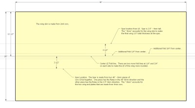 [/link]
[link=http://www.frostracing.com/RC/07aspadtwist/SPAD%20Twist-VSF%20Aileron%20Guides-big.jpg]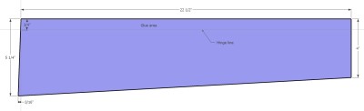 [/link]
2. Be sure to score the wing skin in the five places as shown. Fold each score line several times.
3. Draw lines on the inside top and bottom wing skins in the location of the spar.
4. Use CA to glue the ailerons to the inside of the bottom part of the wing skin. You will need to cut a 4mil filler piece for the center of the wing between the ailerons. Glue the filler piece in with CA.
5. Test the wing skin fit by folding over the top part of the wing skin. Check that the TE of the 2mil top wing skin is aligned with the TE of the bottom 2mil wing skin.
6. When satisfied, glue the wing top skin to the ailerons pieces with CA. Tape the top wing skin to a piece of wood so that you can accurately place the 48” long top wing skin onto the aileron pieces squarely.
7. Use CA to glue the two pieces of 4mil spar material together. Let the glue dry for a while.
8. Use a wide 6 foot straight edge inserted and twisted into the wing to hold the wing open for spar insertion.
9. Apply Goop glue to the top and bottom of the spar and insert the spar into the wing. Remove the 6 foot straight edge and position the spar into place. You may have to use a broom handle to push around the spar in the center of the wing. When the spar is aligned, let the goop glue dry overnight.
10. Use poster board to create 2 templates for the wing’s profile. Cut 2mil off the circumference of one of the templates. The other template will be used to create the cutout in the fuse for the wing.
[link=http://www.frostracing.com/RC/07aspadtwist/800x600/img_0303.jpg]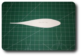 [/link]
[link=http://www.frostracing.com/RC/07aspadtwist/800x600/img_0308.jpg]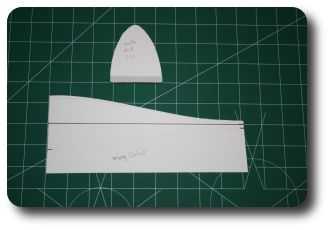 [/link]
11. Use the smaller template to cut 4mil pieces to fill in each end of the wing. The flutes should run vertical for the wing end plates.
12. Glue the wing end plates in using Goop glue.
13. Set the wing aside and move on to the fuse. The center LE cutout channel will be made later.
[link=http://www.frostracing.com/RC/07aspadtwist/800x600/img_0264.jpg]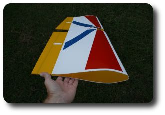 [/link]
The Google SketchUp files for each part:
[link=http://www.frostracing.com/RC/07aspadtwist/SPAD%20Twist-VSF%20Horizontal%20Guides.skp]Horizontal[/link]
[link=http://www.frostracing.com/RC/07aspadtwist/SPAD%20Twist-VSF%20Vertical%20Guides.skp]Vertical[/link]
[link=http://www.frostracing.com/RC/07aspadtwist/SPAD%20Twist-VSF%20Fuse.skp]Fuse[/link]
[link=http://www.frostracing.com/RC/07aspadtwist/SPAD%20Twist-VSF%20Fuse%20Wing%20Cutout.skp]Fuse Wing Cutout[/link]
[link=http://www.frostracing.com/RC/07aspadtwist/SPAD%20Twist-VSF%20Wing%20Guides.skp]Wing[/link]
[link=http://www.frostracing.com/RC/07aspadtwist/SPAD%20Twist-VSF%20Aileron%20Guides.skp]Aileron[/link]
[link=http://www.frostracing.com/RC/07aspadtwist/SPAD%20Twist-VSF%20PVC%20Supports.skp]PVC Supports[/link]
SPAD Twist-VSF assembly instructions
Wing
1. Cut out the wing skin, spar, and aileron pieces.
[link=http://www.frostracing.com/RC/07aspadtwist/SPAD%20Twist-VSF%20Wing%20Guides-big.jpg]
[/link][link=http://www.frostracing.com/RC/07aspadtwist/SPAD%20Twist-VSF%20Aileron%20Guides-big.jpg]
[/link]2. Be sure to score the wing skin in the five places as shown. Fold each score line several times.
3. Draw lines on the inside top and bottom wing skins in the location of the spar.
4. Use CA to glue the ailerons to the inside of the bottom part of the wing skin. You will need to cut a 4mil filler piece for the center of the wing between the ailerons. Glue the filler piece in with CA.
5. Test the wing skin fit by folding over the top part of the wing skin. Check that the TE of the 2mil top wing skin is aligned with the TE of the bottom 2mil wing skin.
6. When satisfied, glue the wing top skin to the ailerons pieces with CA. Tape the top wing skin to a piece of wood so that you can accurately place the 48” long top wing skin onto the aileron pieces squarely.
7. Use CA to glue the two pieces of 4mil spar material together. Let the glue dry for a while.
8. Use a wide 6 foot straight edge inserted and twisted into the wing to hold the wing open for spar insertion.
9. Apply Goop glue to the top and bottom of the spar and insert the spar into the wing. Remove the 6 foot straight edge and position the spar into place. You may have to use a broom handle to push around the spar in the center of the wing. When the spar is aligned, let the goop glue dry overnight.
10. Use poster board to create 2 templates for the wing’s profile. Cut 2mil off the circumference of one of the templates. The other template will be used to create the cutout in the fuse for the wing.
[link=http://www.frostracing.com/RC/07aspadtwist/800x600/img_0303.jpg]
[/link][link=http://www.frostracing.com/RC/07aspadtwist/800x600/img_0308.jpg]
[/link]11. Use the smaller template to cut 4mil pieces to fill in each end of the wing. The flutes should run vertical for the wing end plates.
12. Glue the wing end plates in using Goop glue.
13. Set the wing aside and move on to the fuse. The center LE cutout channel will be made later.
[link=http://www.frostracing.com/RC/07aspadtwist/800x600/img_0264.jpg]
[/link]
06-10-2009, 11:40 AM
#5
Member
Thread Starter
Join Date: Oct 2004
Location: Lawton, OK
Posts: 53
Likes: 0
Received 0 Likes
on
0 Posts
SPAD Twist-VSF assembly instructions
Fuse
1. Cut out the fuse, horizontal stab, and vertical stab 4mil pieces
[link=http://www.frostracing.com/RC/07aspadtwist/SPAD%20Twist-VSF%20Fuse-big.jpg]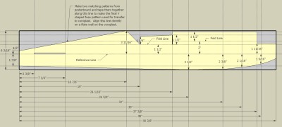 [/link]
[link=http://www.frostracing.com/RC/07aspadtwist/SPAD%20Twist-VSF%20Fuse%20Wing%20Cutout-big.jpg]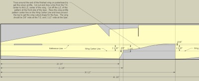 [/link]
[link=http://www.frostracing.com/RC/07aspadtwist/800x600/img_0315.jpg][/link]
[link=http://www.frostracing.com/RC/07aspadtwist/SPAD%20Twist-VSF%20Horizontal%20Guides-big.jpg] [/link]
[link=http://www.frostracing.com/RC/07aspadtwist/SPAD%20Twist-VSF%20Vertical%20Guides-big.jpg]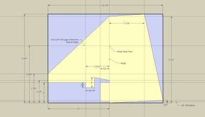 [/link]
2. Cut the elevator hinge on the bottom of the horizontal stab
3. Use a 1/8” steel rod to create a C-shaped joiner for each elevator half:
5. Be sure to cut the slots for the horizontal stab and vertical stab into the fuse. The vertical stab slot starts 1 3/8" from the back of the fuse and is 4 5/8" long. Cut a pie sliced shaped area at the back of the horizontal slot for clearance of the elevator joiner rod. The slot for the vertical stab will be troublesome when folding over the turtle deck. You will have to remove material on the inside of the fuse from each side of the slot to get the turtle deck to lay down nicely next to the vertical stabilizer. Here is a picture of my after-the-fact sloppy elevator joiner rod clearance hole in the fuse:
[link=http://www.frostracing.com/RC/09spadtwist/800x600/100_0490.jpg]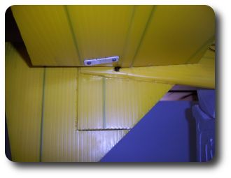 [/link]
6. Score and fold the tabs on the V shaped fuse that will become the top of the fuse and cockpit area.
7. Cut two strips of PVC from American downspout about 3/4” by 2 3/8”.
8. Cut two 1” sections of American downspout. One will be used in the firewall area. The other one will be temporarily used to join the fuse in front of the cockpit.
[link=http://www.frostracing.com/RC/07aspadtwist/800x600/img_0333.jpg][/link]
9. Fold the fuse into shape and use the 1” section of downspout at the firewall area to hold the front together - make sure the sides of fuse contact the downspout. Screw 1/2” long #4 sheet metal screws into each top fuse tab and into the downspout (drill a pilot hole first). The location of the screws should be at least 3/8” behind the front of the downspout. This leaves space for a 3/8” HDPE firewall. Hold the bottom of fuse together against the downspout with tape.
[link=http://www.frostracing.com/RC/07aspadtwist/SPAD%20Twist-VSF%20Model-top.jpg]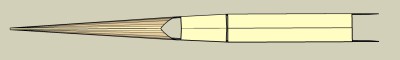 [/link]
[link=http://www.frostracing.com/RC/07aspadtwist/SPAD%20Twist-VSF%20Model-side.jpg]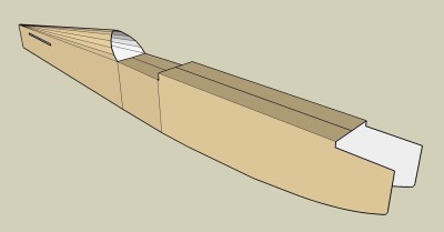 [/link]
10. Put the other 1” section of down spout in front of the cockpit and make sure the sides of fuse contact the downspout. Screw 1/2” long #4 sheet metal screws into each top tab and into the downspout.
11. Use one of 3/4” x 2 3/8” strips on the inside of cockpit floor at the front. Drill pilot holes through each tab and into the PVC strip. Don’t drill into your finger. Screw 1/2” long #4 sheet metal screws into each top tab and into the downspout. You can kind-of see the screw locations in the top of the fuse in this picture - four of the screws are inside the canopy and the other two screws are at the front, near the engine.
[link=http://www.frostracing.com/RC/07aspadtwist/800x600/img_0283.jpg][/link]
12. Now your fuse is “fusey” looking but very floppy.
13. Double over the elevator halves onto the horizontal stab and slide it into the slots in the fuse. It will be a tight squeeze. Insert it so that the hinge slot is on the bottom eventually. Don’t glue the piece in yet.
14. Make sure the fuse is not curved like a banana to the left or right by viewing the fuse from the top. Hold the fuse vertically at arms length and eyeball it.
15. When you are happy that fuse is not curved like a banana, turn the fuse over and glue a 1” strip of 2 mil coro over the seam on the inside of the fuse with CA. There will be two strips of 1” 2 mil coro needed. One between the firewall PVC downspout and the back piece of PVC downspout, and the second one on the cockpit floor.
16. After the glue dries, replace the temporary PVC downspout in front of the cockpit with the 3/4” x 2 3/8” strip of PVC.
17. Make the landing gear/wing support structure as shown in a post above. Test fit the PVC downspout into the fuse before making the HDPE cutting board pieces. The LG/Wing mount needs to be angled to follow the contour of the bottom of the fuse, but the wing mount face needs to be flush with the front of the wing saddle. The angle between the LG mount face and Wing mount face is about 86 degrees.
[link=http://www.frostracing.com/RC/07aspadtwist/SPAD%20Twist-VSF%20PVC%20Supports%20Front-big.jpg]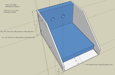 [/link]
[link=http://www.frostracing.com/RC/09spadtwist/800x600/100_0493.jpg]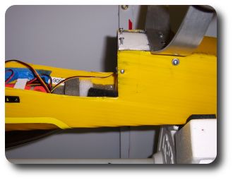 [/link]
18. Test fit the LG/Wing support. Cut holes into the inner wall of the fuse to clear the screw heads in the LG/Wing support. Once you are happy with the fit, glue the LG/Wing support in with Goop. Use tape to hold the fuse together. Let the Goop dry overnight.
[link=http://www.frostracing.com/RC/07aspadtwist/800x600/img_0324.jpg][/link]
19. Drill a pilot hole at the top of the wing support area and the front of the landing gear support area. Make sure the pilot hole goes into the HDPE cutting board material at each location. Screw in 1/2” long #4 sheet metal screws into the LG/Wing support on each side of the fuse. One of the screws will be beneath the wing channel/fuse overlap. The other screw is outside the wing channel/fuse overlap. (These screws are not shown in the earlier photo above, these screws were added later after I knocked the LG/Wing mount half loose once)
[link=http://www.frostracing.com/RC/09spadtwist/800x600/100_0492.jpg]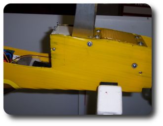 [/link]
20. Take out the firewall PVC downspout. It is not tall enough to reach the bottom of the fuse, so cut it 5/8" from the top on the sides to create two pieces. The firewall will eventually be 3 1/2" tall.
21. Re-install the top piece of the firewall PVC downspout with CA. Make sure the screw holes line up first. Re-insert the screws.
22. Line up the bottom piece of the firewall PVC downspout with the bottom of the fuse and even with the top firewall PVC piece. We are making a rectangle shape for the HDPE firewall here. Glue it in with CA. Drill a pilot hole into the bottom PVC downspout piece on each side of the fuse. These holes should be lined up vertically with the holes in the top of the fuse. Screw in 1/2” long #4 sheet metal screws into these holes.
[link=http://www.frostracing.com/RC/07aspadtwist/800x600/img_0327.jpg][/link]
[link=http://www.frostracing.com/RC/09spadtwist/800x600/100_0495.jpg]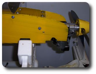 [/link]
23. Cut two filler pieces of PVC downspout to fill in the area between existing top and bottom PVC downspout firewall pieces. Glue these in with CA.
24. Cut a 3/8” thick piece of HDPE cutting board to fill the entire rectangle firewall space - around 2 1/2" x 3 1/2". Insert in the HDPE firewall flush with the front of the PVC. Drill one pilot hole into the center of the top/bottom/left side/right side of the fuse into the HDPE material. Use a hot piece of brass tubing to puncture a hole through the 4mil at each hole. Use 3/4” #4 sheet metal screws to screw into the holes to retain the HDPE firewall.
[link=http://www.frostracing.com/RC/09spadtwist/800x600/100_0495.jpg][/link]
25. Cut a strip of PVC to be used for the back wing mount. Bend into a C shape to fit at the back of the wing cutout area. The bends will not be square due to the taper of the fuse at this area. Glue a piece of HDPE cutting board on the inside of the C shape for the rear wing attachment bolt to go into. Glue the back wing mount in with Goop glue. Drill a pilot hole on each side of the fuse into the legs of the C shaped wing mount and screw in 1/2” #4 sheet metal screws.
[link=http://www.frostracing.com/RC/07aspadtwist/800x600/img_0323.jpg][/link]
26. Insert the Vertical stab into the fuse slot. The bottom of the forward part of the vertical stab should contact the horizontal stab inside the fuse.
27. After you are satisfied with the fit of the Vertical stab remove it.
28. Align the horizontal stab and mark lines on the stab against the fuse to be used as alignment lines after applying glue.
29. Apply Goop glue to the bottom horizontal stab on the inside of the fuse. Slide the horizontal stab around a little to smear the glue around a bit. Re-align the horizontal stab using the lines drawn earlier.
30. Flip over the fuse. Use Goop glue to glue the vertical stab into the fuse. The goop should be applied to the bottom of the forward part of the stab where it contacts the horizontal stab, to the tab that is inserted in the rear of the fuse, and the area where the turtle deck contacts the vertical stab. Align the vertical stab for, you know, verticalness. You may have to use blue painters tape or sewing pins (until the glue dries) to hold the turtle deck skin flush against the vertical stab for a nice smooth look.
[link=http://www.frostracing.com/RC/07aspadtwist/800x600/img_0283.jpg][/link]
31. Turn the fuse back upside down. Cut a small former from 4mil to be placed 7" from the rear of the fuse over the horizontal stab. Leave 4mil worth of space for the fuse bottom to be inserted later. Glue in with Goop.
32. Cut two more formers to be spaced at 10 1/4" and 16 1/2" from the rear of the fuse in the turtle deck area from 4mil. The formers should be curved on one end to match the turtle deck shape, the flutes should be vertical. Leave the formers short enough to slide servo wires between them and the fuse bottom (that will be installed later). Of course one former will be smaller than the other. Glue them in with Goop and use tape the hold the bottom of the fuse together tight against the formers.
33. Lay a piece of 4mil over the bottom back of the fuse with the flutes running perpendicular to the fuse. Trace a line on the bottom of the piece around the rear fuse. Leave enough spare material at the front of this piece to bend down to the rear wing mount area. Cut the piece to fit. This piece will be interlocked with the fuse sides by cutting a 4 mm wide channel around its perimeter. This is done by using a hobby knife and cutting each flute a little first – it does not have to be real accurate yet. Then cut on a line on the inside of the bottom piece that is 4 mm inside the edge of it. Grab an end of the piece to be removed and pull it from one end – it will easily pull away tearing each flute like a perforated joint as you go. Now use a Dremel tool with a sanding drum to remove the remaining portions of the flutes from the coro skin. Be careful not to sand through the coro skin. Making this piece is easier then describing how to make it, so don’t fret. Test fit the piece. Cut the inside of the flutes (like a hinge) in the area where the bottom piece angles down to the rear wing mount so that the bottom piece lays down nicely. Apply Goop glue to the interlocking portion of the bottom piece and glue the piece in place – use tape to hold the piece down at the front, middle, and back.
[link=http://www.youtube.com/watch?v=iN_FyygAmDY]YouTube Video[/link] of making the 4mil interlocking channel.
[link=http://www.frostracing.com/RC/07aspadtwist/800x600/img_0329.jpg]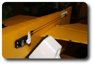 [/link]
[link=http://www.frostracing.com/RC/07aspadtwist/800x600/img_0323.jpg][/link]
34. Lay a smaller piece of 4mil over the front of the fuse from the firewall PVC to 1/2” onto the LG/Wing support PVC. The flutes run perpendicular to the fuse. Trace a line on the bottom of the piece and cut the piece to fit. Make a 4 mm interlocking channel on the sides like described above. Remove the flutes and the inside of the coro skin in the area that overlaps the LG/Wing support PVC. This bottom front fuse cover will be held on with four #4 sheet metal screws – two at the back and two at the front. Leave the piece off of the fuse for now.
[link=http://www.frostracing.com/RC/07aspadtwist/800x600/img_0327.jpg][/link]
35. Flip the fuse over to upright. Use a piece of poster board to create a template of the hole at the front of turtle deck / rear of the cockpit. About 1/2” inch of the template should be on the cockpit floor and the rest of the template bent up to the top of the turtle deck. Trace around the outside of the turtle deck onto the template to get the contour correct. Copy the template shape to a piece of 4mil with the flutes running horizontal (parallel to the cockpit floor). Cut a 4 mm interlocking channel around the perimeter of the piece like described above. Remove the flutes and one side of the coro skin where 1/2” of the piece bends and contacts the rear of the cockpit floor. Glue the piece in with Goop.
[link=http://www.frostracing.com/RC/07aspadtwist/800x600/img_0308.jpg][/link]
36. Cut a small piece to fill in the dash hole at the front of the cockpit. It should be mounted flush with an interlocking 4mm channel on the top and sides – this is easy to do if the flutes are horizontal to the fuse. Glue the piece in with Goop.
37. Make a canopy from a 3 liter soda bottle or you can order the Twist-40 canopy from Horizon Hobby. Glue the canopy on with Goop.
[link=http://www.frostracing.com/RC/07aspadtwist/800x600/img_0288.jpg][/link]
Next Up - Wing/Fuse Mating
Fuse
1. Cut out the fuse, horizontal stab, and vertical stab 4mil pieces
[link=http://www.frostracing.com/RC/07aspadtwist/SPAD%20Twist-VSF%20Fuse-big.jpg]
[/link][link=http://www.frostracing.com/RC/07aspadtwist/SPAD%20Twist-VSF%20Fuse%20Wing%20Cutout-big.jpg]
[/link][link=http://www.frostracing.com/RC/07aspadtwist/800x600/img_0315.jpg]
[/link][link=http://www.frostracing.com/RC/07aspadtwist/SPAD%20Twist-VSF%20Horizontal%20Guides-big.jpg]
[/link][link=http://www.frostracing.com/RC/07aspadtwist/SPAD%20Twist-VSF%20Vertical%20Guides-big.jpg]
[/link]2. Cut the elevator hinge on the bottom of the horizontal stab
3. Use a 1/8” steel rod to create a C-shaped joiner for each elevator half:
5. Be sure to cut the slots for the horizontal stab and vertical stab into the fuse. The vertical stab slot starts 1 3/8" from the back of the fuse and is 4 5/8" long. Cut a pie sliced shaped area at the back of the horizontal slot for clearance of the elevator joiner rod. The slot for the vertical stab will be troublesome when folding over the turtle deck. You will have to remove material on the inside of the fuse from each side of the slot to get the turtle deck to lay down nicely next to the vertical stabilizer. Here is a picture of my after-the-fact sloppy elevator joiner rod clearance hole in the fuse:
[link=http://www.frostracing.com/RC/09spadtwist/800x600/100_0490.jpg]
[/link]6. Score and fold the tabs on the V shaped fuse that will become the top of the fuse and cockpit area.
7. Cut two strips of PVC from American downspout about 3/4” by 2 3/8”.
8. Cut two 1” sections of American downspout. One will be used in the firewall area. The other one will be temporarily used to join the fuse in front of the cockpit.
[link=http://www.frostracing.com/RC/07aspadtwist/800x600/img_0333.jpg]
[/link]9. Fold the fuse into shape and use the 1” section of downspout at the firewall area to hold the front together - make sure the sides of fuse contact the downspout. Screw 1/2” long #4 sheet metal screws into each top fuse tab and into the downspout (drill a pilot hole first). The location of the screws should be at least 3/8” behind the front of the downspout. This leaves space for a 3/8” HDPE firewall. Hold the bottom of fuse together against the downspout with tape.
[link=http://www.frostracing.com/RC/07aspadtwist/SPAD%20Twist-VSF%20Model-top.jpg]
[/link][link=http://www.frostracing.com/RC/07aspadtwist/SPAD%20Twist-VSF%20Model-side.jpg]
[/link]10. Put the other 1” section of down spout in front of the cockpit and make sure the sides of fuse contact the downspout. Screw 1/2” long #4 sheet metal screws into each top tab and into the downspout.
11. Use one of 3/4” x 2 3/8” strips on the inside of cockpit floor at the front. Drill pilot holes through each tab and into the PVC strip. Don’t drill into your finger. Screw 1/2” long #4 sheet metal screws into each top tab and into the downspout. You can kind-of see the screw locations in the top of the fuse in this picture - four of the screws are inside the canopy and the other two screws are at the front, near the engine.
[link=http://www.frostracing.com/RC/07aspadtwist/800x600/img_0283.jpg]
[/link]12. Now your fuse is “fusey” looking but very floppy.
13. Double over the elevator halves onto the horizontal stab and slide it into the slots in the fuse. It will be a tight squeeze. Insert it so that the hinge slot is on the bottom eventually. Don’t glue the piece in yet.
14. Make sure the fuse is not curved like a banana to the left or right by viewing the fuse from the top. Hold the fuse vertically at arms length and eyeball it.
15. When you are happy that fuse is not curved like a banana, turn the fuse over and glue a 1” strip of 2 mil coro over the seam on the inside of the fuse with CA. There will be two strips of 1” 2 mil coro needed. One between the firewall PVC downspout and the back piece of PVC downspout, and the second one on the cockpit floor.
16. After the glue dries, replace the temporary PVC downspout in front of the cockpit with the 3/4” x 2 3/8” strip of PVC.
17. Make the landing gear/wing support structure as shown in a post above. Test fit the PVC downspout into the fuse before making the HDPE cutting board pieces. The LG/Wing mount needs to be angled to follow the contour of the bottom of the fuse, but the wing mount face needs to be flush with the front of the wing saddle. The angle between the LG mount face and Wing mount face is about 86 degrees.
[link=http://www.frostracing.com/RC/07aspadtwist/SPAD%20Twist-VSF%20PVC%20Supports%20Front-big.jpg]
[/link][link=http://www.frostracing.com/RC/09spadtwist/800x600/100_0493.jpg]
[/link]18. Test fit the LG/Wing support. Cut holes into the inner wall of the fuse to clear the screw heads in the LG/Wing support. Once you are happy with the fit, glue the LG/Wing support in with Goop. Use tape to hold the fuse together. Let the Goop dry overnight.
[link=http://www.frostracing.com/RC/07aspadtwist/800x600/img_0324.jpg]
[/link]19. Drill a pilot hole at the top of the wing support area and the front of the landing gear support area. Make sure the pilot hole goes into the HDPE cutting board material at each location. Screw in 1/2” long #4 sheet metal screws into the LG/Wing support on each side of the fuse. One of the screws will be beneath the wing channel/fuse overlap. The other screw is outside the wing channel/fuse overlap. (These screws are not shown in the earlier photo above, these screws were added later after I knocked the LG/Wing mount half loose once)
[link=http://www.frostracing.com/RC/09spadtwist/800x600/100_0492.jpg]
[/link]20. Take out the firewall PVC downspout. It is not tall enough to reach the bottom of the fuse, so cut it 5/8" from the top on the sides to create two pieces. The firewall will eventually be 3 1/2" tall.
21. Re-install the top piece of the firewall PVC downspout with CA. Make sure the screw holes line up first. Re-insert the screws.
22. Line up the bottom piece of the firewall PVC downspout with the bottom of the fuse and even with the top firewall PVC piece. We are making a rectangle shape for the HDPE firewall here. Glue it in with CA. Drill a pilot hole into the bottom PVC downspout piece on each side of the fuse. These holes should be lined up vertically with the holes in the top of the fuse. Screw in 1/2” long #4 sheet metal screws into these holes.
[link=http://www.frostracing.com/RC/07aspadtwist/800x600/img_0327.jpg]
[/link][link=http://www.frostracing.com/RC/09spadtwist/800x600/100_0495.jpg]
[/link]23. Cut two filler pieces of PVC downspout to fill in the area between existing top and bottom PVC downspout firewall pieces. Glue these in with CA.
24. Cut a 3/8” thick piece of HDPE cutting board to fill the entire rectangle firewall space - around 2 1/2" x 3 1/2". Insert in the HDPE firewall flush with the front of the PVC. Drill one pilot hole into the center of the top/bottom/left side/right side of the fuse into the HDPE material. Use a hot piece of brass tubing to puncture a hole through the 4mil at each hole. Use 3/4” #4 sheet metal screws to screw into the holes to retain the HDPE firewall.
[link=http://www.frostracing.com/RC/09spadtwist/800x600/100_0495.jpg]
[/link]25. Cut a strip of PVC to be used for the back wing mount. Bend into a C shape to fit at the back of the wing cutout area. The bends will not be square due to the taper of the fuse at this area. Glue a piece of HDPE cutting board on the inside of the C shape for the rear wing attachment bolt to go into. Glue the back wing mount in with Goop glue. Drill a pilot hole on each side of the fuse into the legs of the C shaped wing mount and screw in 1/2” #4 sheet metal screws.
[link=http://www.frostracing.com/RC/07aspadtwist/800x600/img_0323.jpg]
[/link]26. Insert the Vertical stab into the fuse slot. The bottom of the forward part of the vertical stab should contact the horizontal stab inside the fuse.
27. After you are satisfied with the fit of the Vertical stab remove it.
28. Align the horizontal stab and mark lines on the stab against the fuse to be used as alignment lines after applying glue.
29. Apply Goop glue to the bottom horizontal stab on the inside of the fuse. Slide the horizontal stab around a little to smear the glue around a bit. Re-align the horizontal stab using the lines drawn earlier.
30. Flip over the fuse. Use Goop glue to glue the vertical stab into the fuse. The goop should be applied to the bottom of the forward part of the stab where it contacts the horizontal stab, to the tab that is inserted in the rear of the fuse, and the area where the turtle deck contacts the vertical stab. Align the vertical stab for, you know, verticalness. You may have to use blue painters tape or sewing pins (until the glue dries) to hold the turtle deck skin flush against the vertical stab for a nice smooth look.
[link=http://www.frostracing.com/RC/07aspadtwist/800x600/img_0283.jpg]
[/link]31. Turn the fuse back upside down. Cut a small former from 4mil to be placed 7" from the rear of the fuse over the horizontal stab. Leave 4mil worth of space for the fuse bottom to be inserted later. Glue in with Goop.
32. Cut two more formers to be spaced at 10 1/4" and 16 1/2" from the rear of the fuse in the turtle deck area from 4mil. The formers should be curved on one end to match the turtle deck shape, the flutes should be vertical. Leave the formers short enough to slide servo wires between them and the fuse bottom (that will be installed later). Of course one former will be smaller than the other. Glue them in with Goop and use tape the hold the bottom of the fuse together tight against the formers.
33. Lay a piece of 4mil over the bottom back of the fuse with the flutes running perpendicular to the fuse. Trace a line on the bottom of the piece around the rear fuse. Leave enough spare material at the front of this piece to bend down to the rear wing mount area. Cut the piece to fit. This piece will be interlocked with the fuse sides by cutting a 4 mm wide channel around its perimeter. This is done by using a hobby knife and cutting each flute a little first – it does not have to be real accurate yet. Then cut on a line on the inside of the bottom piece that is 4 mm inside the edge of it. Grab an end of the piece to be removed and pull it from one end – it will easily pull away tearing each flute like a perforated joint as you go. Now use a Dremel tool with a sanding drum to remove the remaining portions of the flutes from the coro skin. Be careful not to sand through the coro skin. Making this piece is easier then describing how to make it, so don’t fret. Test fit the piece. Cut the inside of the flutes (like a hinge) in the area where the bottom piece angles down to the rear wing mount so that the bottom piece lays down nicely. Apply Goop glue to the interlocking portion of the bottom piece and glue the piece in place – use tape to hold the piece down at the front, middle, and back.
[link=http://www.youtube.com/watch?v=iN_FyygAmDY]YouTube Video[/link] of making the 4mil interlocking channel.
[link=http://www.frostracing.com/RC/07aspadtwist/800x600/img_0329.jpg]
[/link][link=http://www.frostracing.com/RC/07aspadtwist/800x600/img_0323.jpg]
[/link]34. Lay a smaller piece of 4mil over the front of the fuse from the firewall PVC to 1/2” onto the LG/Wing support PVC. The flutes run perpendicular to the fuse. Trace a line on the bottom of the piece and cut the piece to fit. Make a 4 mm interlocking channel on the sides like described above. Remove the flutes and the inside of the coro skin in the area that overlaps the LG/Wing support PVC. This bottom front fuse cover will be held on with four #4 sheet metal screws – two at the back and two at the front. Leave the piece off of the fuse for now.
[link=http://www.frostracing.com/RC/07aspadtwist/800x600/img_0327.jpg]
[/link]35. Flip the fuse over to upright. Use a piece of poster board to create a template of the hole at the front of turtle deck / rear of the cockpit. About 1/2” inch of the template should be on the cockpit floor and the rest of the template bent up to the top of the turtle deck. Trace around the outside of the turtle deck onto the template to get the contour correct. Copy the template shape to a piece of 4mil with the flutes running horizontal (parallel to the cockpit floor). Cut a 4 mm interlocking channel around the perimeter of the piece like described above. Remove the flutes and one side of the coro skin where 1/2” of the piece bends and contacts the rear of the cockpit floor. Glue the piece in with Goop.
[link=http://www.frostracing.com/RC/07aspadtwist/800x600/img_0308.jpg]
[/link]36. Cut a small piece to fill in the dash hole at the front of the cockpit. It should be mounted flush with an interlocking 4mm channel on the top and sides – this is easy to do if the flutes are horizontal to the fuse. Glue the piece in with Goop.
37. Make a canopy from a 3 liter soda bottle or you can order the Twist-40 canopy from Horizon Hobby. Glue the canopy on with Goop.
[link=http://www.frostracing.com/RC/07aspadtwist/800x600/img_0288.jpg]
[/link]Next Up - Wing/Fuse Mating
06-10-2009, 11:42 AM
#6
Member
Thread Starter
Join Date: Oct 2004
Location: Lawton, OK
Posts: 53
Likes: 0
Received 0 Likes
on
0 Posts
Wing/Fuse Mating
1. Measure the outside width of the fuse at the LG/Wing mount. Cut a 3 1/2 inch deep channel into the center of the wing at the LE as wide as the fuse at the LG/Wing mount area. Use a portion of the wing endplate templates from before to create two 4mil inner endplates for each side of the 3 1/2” channel. The flutes should run in the same direction as the wing endplates (vertical). Glue (with Goop) these pieces in flush with the wing skin edge. The area from the LE to the spar should be filled by these pieces.
[link=http://www.frostracing.com/RC/07aspadtwist/800x600/img_0261.jpg]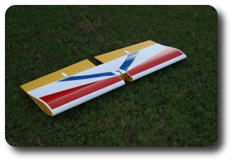 [/link]
2. Test fit the wing into the fuse wing saddle. The LE cut out should fit
snuggly around the fuse. The TE of the wing should be flat against the rear wing mount. The thickest part of the wing should be within an imaginary line from the bottom of the LG/Wing mount to the back bottom fuse cover.
3. Align the wing with the fuse. The LE of the wing should be perpendicular to the front of the fuse. Drill 2 pilot holes through the back of the wing into the rear wing mount HDPE block. You can drill and tap the rear wing mount holes for 8-32 nylon bolts or use long #6 sheet metal screws to secure the back of the wing. Cut a small strip of PVC downspout to use to spread the load of the bolts/screws. Glue the PVC piece on with Goop and secure the back of the wing with the bolts/screws.
4. From the inside front of the fuse drill two 1/4” holes into the spar using the 1/4” holes in the LG/Wing mount as guides.
5. Remove the wing. Use Goop to glue two 1/4” wood dowels into the holes in the spar created above. The dowels should extend a little over 3/8” out of the spar.
[link=http://www.frostracing.com/RC/07aspadtwist/800x600/img_0262.jpg]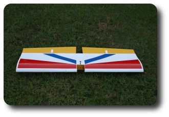 [/link]
6. Cut an L shaped piece of PVC downspout. The piece should fit flush to the bottom of the LG/Wing mount (1” long part) and reach just past the 1/4” holes in the front wing mount. Drill two 1/4” holes into the PVC using the LG/Wing mount holes as a guide. Slide this piece over the dowels in the wing with the short part of the L facing forward and use Goop to glue it to the wing spar. Drill 4 evenly spaced pilot holes through the L into the spar and screw 1/2” #4 sheet metal screws into the holes – apply Goop glue to the threads of the screws first. (this piece did not exist when I first flew the plane, I added it later to eliminate fuse flexing and wing wobbling)
[link=http://www.frostracing.com/RC/09spadtwist/800x600/100_0486.jpg]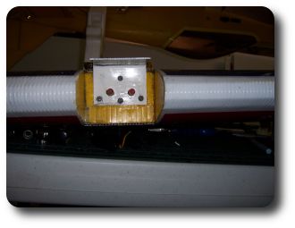 [/link]
[link=http://www.frostracing.com/RC/09spadtwist/800x600/100_0487.jpg]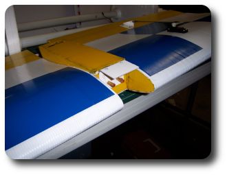 [/link]
7. Test fit the wing again. Slide the LE in first to engage the dowels into the LG/Wing mount and push down the TE to the rear wing mount. Secure the back of the wing with the screws/bolts. Drill two pilot holes through the short part of the L piece into the LG/Wing mount bottom. Be sure to drill into the HDPE on the bottom of the LG/Wing mount. Use two #6 screws (or drill and tap for 8-32 nylon bolts) to secure the L piece to the bottom of the LG/Wing mount.
8. Use the wing saddle template to create a template for the side pieces of the wing belly pan. Use the resulting template to cut two 4mil pieces of coro – the flutes should run parallel to the wing chord. Align these pieces with the fuse line from the back to the front of the wing and glue them to the wing with Goop. Be sure the pieces are perpendicular to the wing skin.
[link=http://www.frostracing.com/RC/07aspadtwist/800x600/img_0306.jpg]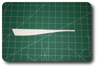 [/link]
9. Make a 4mil coro piece to cover the bottom of the belly pan. Make the piece interlocking as described in Fuse step 33. Cut a hole in the back of this piece for access to the rear wing mount screws. Glue the belly pan bottom to the belly pan side pieces with Goop.
[link=http://www.frostracing.com/RC/07aspadtwist/800x600/img_0256.jpg]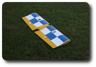 [/link]
[link=http://www.frostracing.com/RC/09spadtwist/800x600/100_0488.jpg]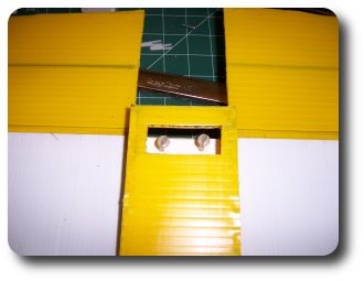 [/link]
1. Measure the outside width of the fuse at the LG/Wing mount. Cut a 3 1/2 inch deep channel into the center of the wing at the LE as wide as the fuse at the LG/Wing mount area. Use a portion of the wing endplate templates from before to create two 4mil inner endplates for each side of the 3 1/2” channel. The flutes should run in the same direction as the wing endplates (vertical). Glue (with Goop) these pieces in flush with the wing skin edge. The area from the LE to the spar should be filled by these pieces.
[link=http://www.frostracing.com/RC/07aspadtwist/800x600/img_0261.jpg]
[/link]2. Test fit the wing into the fuse wing saddle. The LE cut out should fit
snuggly around the fuse. The TE of the wing should be flat against the rear wing mount. The thickest part of the wing should be within an imaginary line from the bottom of the LG/Wing mount to the back bottom fuse cover.
3. Align the wing with the fuse. The LE of the wing should be perpendicular to the front of the fuse. Drill 2 pilot holes through the back of the wing into the rear wing mount HDPE block. You can drill and tap the rear wing mount holes for 8-32 nylon bolts or use long #6 sheet metal screws to secure the back of the wing. Cut a small strip of PVC downspout to use to spread the load of the bolts/screws. Glue the PVC piece on with Goop and secure the back of the wing with the bolts/screws.
4. From the inside front of the fuse drill two 1/4” holes into the spar using the 1/4” holes in the LG/Wing mount as guides.
5. Remove the wing. Use Goop to glue two 1/4” wood dowels into the holes in the spar created above. The dowels should extend a little over 3/8” out of the spar.
[link=http://www.frostracing.com/RC/07aspadtwist/800x600/img_0262.jpg]
[/link]6. Cut an L shaped piece of PVC downspout. The piece should fit flush to the bottom of the LG/Wing mount (1” long part) and reach just past the 1/4” holes in the front wing mount. Drill two 1/4” holes into the PVC using the LG/Wing mount holes as a guide. Slide this piece over the dowels in the wing with the short part of the L facing forward and use Goop to glue it to the wing spar. Drill 4 evenly spaced pilot holes through the L into the spar and screw 1/2” #4 sheet metal screws into the holes – apply Goop glue to the threads of the screws first. (this piece did not exist when I first flew the plane, I added it later to eliminate fuse flexing and wing wobbling)
[link=http://www.frostracing.com/RC/09spadtwist/800x600/100_0486.jpg]
[/link][link=http://www.frostracing.com/RC/09spadtwist/800x600/100_0487.jpg]
[/link]7. Test fit the wing again. Slide the LE in first to engage the dowels into the LG/Wing mount and push down the TE to the rear wing mount. Secure the back of the wing with the screws/bolts. Drill two pilot holes through the short part of the L piece into the LG/Wing mount bottom. Be sure to drill into the HDPE on the bottom of the LG/Wing mount. Use two #6 screws (or drill and tap for 8-32 nylon bolts) to secure the L piece to the bottom of the LG/Wing mount.
8. Use the wing saddle template to create a template for the side pieces of the wing belly pan. Use the resulting template to cut two 4mil pieces of coro – the flutes should run parallel to the wing chord. Align these pieces with the fuse line from the back to the front of the wing and glue them to the wing with Goop. Be sure the pieces are perpendicular to the wing skin.
[link=http://www.frostracing.com/RC/07aspadtwist/800x600/img_0306.jpg]
[/link]9. Make a 4mil coro piece to cover the bottom of the belly pan. Make the piece interlocking as described in Fuse step 33. Cut a hole in the back of this piece for access to the rear wing mount screws. Glue the belly pan bottom to the belly pan side pieces with Goop.
[link=http://www.frostracing.com/RC/07aspadtwist/800x600/img_0256.jpg]
[/link][link=http://www.frostracing.com/RC/09spadtwist/800x600/100_0488.jpg]
[/link]
06-10-2009, 11:45 AM
#7
Member
Thread Starter
Join Date: Oct 2004
Location: Lawton, OK
Posts: 53
Likes: 0
Received 0 Likes
on
0 Posts
Final Steps
1. Attach the landing gear 1/2” back from the LE of the LG/Wing Mount. Drill pilot holes through the landing gear and into the HDPE cutting board. Use #6 sheet metal screws to attach the landing gear.
[link=http://www.frostracing.com/RC/07aspadtwist/800x600/img_0327.jpg][/link]
2. Mount the fuel tank and engine.
3. Mount the wing servos and control linkages. The control horns are 2 inches long and 1 inch tall. The control horn backing plates are 2" x 3/4".
[link=http://www.frostracing.com/RC/07aspadtwist/800x600/img_0255.jpg]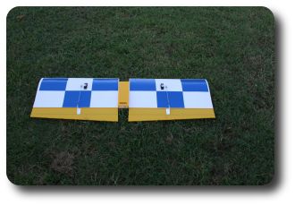 [/link]
4. Mount the tail wheel. The tail wheel wire is bent at 90 degrees at the top and glued in perpendicular to the rudder flutes using Goop.
[link=http://www.frostracing.com/RC/09spadtwist/800x600/100_0485.jpg] [/link]
5. Use .157 carbon fiber rods to insert into the flutes of the ailerons, vertical stabilizer, rudder, horizontal stabilizer, and elevator to stiffen them. I could not force the carbon fiber rod into the elevator counter balances without shattering it, so I used bamboo skewers there. You can chuck the skewers up in a variable speed drill and slowly force them into the counter balances. The dark lines in the coro in this picture are the locations of the carbon fiber rods.
[link=http://www.frostracing.com/RC/07aspadtwist/800x600/img_0284.jpg]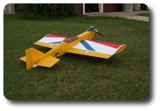 [/link]
6. Use a CG machine to find the best location of the remaining radio gear. Tape the radio gear and control linkages to the plane and check the balance. Balance the plane between 4 and 5 inches from the wing LE. Generally the receiver, battery and switch harness will be in the wing saddle area. The elevator and rudder servos will be in the rear of the fuse. The throttle servo (micro servo) will be in the front under the tank. The throttle servo will probably work in the wing saddle area, because to achieve a CG 5 inches from the wing LE my receiver battery is now located at the very back of the cockpit floor area.
[link=http://www.frostracing.com/RC/07aspadtwist/800x600/img_0326.jpg]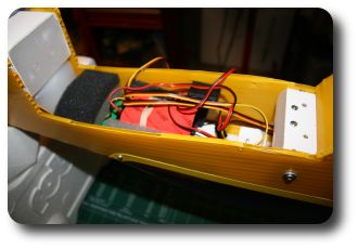 [/link]
[link=http://www.frostracing.com/RC/07aspadtwist/800x600/img_0328.jpg]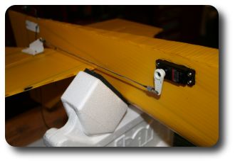 [/link]
[link=http://www.frostracing.com/RC/07aspadtwist/800x600/img_0333.jpg][/link]
7. Once the gear location is decided, cut holes into the fuse for the elevator and rudder servos. Keep in mind where the turtle deck formers are and try to avoid the need to cut into them. The holes should be a snug fit. Insert the servos into the holes and apply Goop glue to the threads of the servo screws before inserting the screws. My elevator servo is 12 1/4" from the back and the rudder servo is 10 5/8" from the back of the fuse.
[link=http://www.frostracing.com/RC/07aspadtwist/800x600/img_0278.jpg]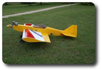 [/link]
[link=http://www.frostracing.com/RC/07aspadtwist/800x600/img_0286.jpg]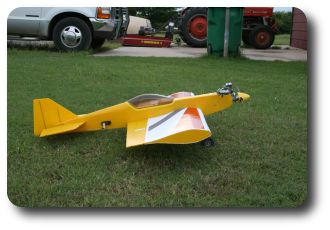 [/link]
Kris
1. Attach the landing gear 1/2” back from the LE of the LG/Wing Mount. Drill pilot holes through the landing gear and into the HDPE cutting board. Use #6 sheet metal screws to attach the landing gear.
[link=http://www.frostracing.com/RC/07aspadtwist/800x600/img_0327.jpg]
[/link]2. Mount the fuel tank and engine.
3. Mount the wing servos and control linkages. The control horns are 2 inches long and 1 inch tall. The control horn backing plates are 2" x 3/4".
[link=http://www.frostracing.com/RC/07aspadtwist/800x600/img_0255.jpg]
[/link]4. Mount the tail wheel. The tail wheel wire is bent at 90 degrees at the top and glued in perpendicular to the rudder flutes using Goop.
[link=http://www.frostracing.com/RC/09spadtwist/800x600/100_0485.jpg]
[/link]5. Use .157 carbon fiber rods to insert into the flutes of the ailerons, vertical stabilizer, rudder, horizontal stabilizer, and elevator to stiffen them. I could not force the carbon fiber rod into the elevator counter balances without shattering it, so I used bamboo skewers there. You can chuck the skewers up in a variable speed drill and slowly force them into the counter balances. The dark lines in the coro in this picture are the locations of the carbon fiber rods.
[link=http://www.frostracing.com/RC/07aspadtwist/800x600/img_0284.jpg]
[/link]6. Use a CG machine to find the best location of the remaining radio gear. Tape the radio gear and control linkages to the plane and check the balance. Balance the plane between 4 and 5 inches from the wing LE. Generally the receiver, battery and switch harness will be in the wing saddle area. The elevator and rudder servos will be in the rear of the fuse. The throttle servo (micro servo) will be in the front under the tank. The throttle servo will probably work in the wing saddle area, because to achieve a CG 5 inches from the wing LE my receiver battery is now located at the very back of the cockpit floor area.
[link=http://www.frostracing.com/RC/07aspadtwist/800x600/img_0326.jpg]
[/link][link=http://www.frostracing.com/RC/07aspadtwist/800x600/img_0328.jpg]
[/link][link=http://www.frostracing.com/RC/07aspadtwist/800x600/img_0333.jpg]
[/link]7. Once the gear location is decided, cut holes into the fuse for the elevator and rudder servos. Keep in mind where the turtle deck formers are and try to avoid the need to cut into them. The holes should be a snug fit. Insert the servos into the holes and apply Goop glue to the threads of the servo screws before inserting the screws. My elevator servo is 12 1/4" from the back and the rudder servo is 10 5/8" from the back of the fuse.
[link=http://www.frostracing.com/RC/07aspadtwist/800x600/img_0278.jpg]
[/link][link=http://www.frostracing.com/RC/07aspadtwist/800x600/img_0286.jpg]
[/link]Kris
06-10-2009, 11:48 AM
#8
Member
Thread Starter
Join Date: Oct 2004
Location: Lawton, OK
Posts: 53
Likes: 0
Received 0 Likes
on
0 Posts
I added a video to explain step 33 of the Fuse - making the interlocking 4mil channel in the bottom piece.
[youtube]http://www.youtube.com/watch?v=iN_FyygAmDY[/youtube]
[youtube]http://www.youtube.com/watch?v=iN_FyygAmDY[/youtube]
10-14-2009, 12:12 PM
#11
Member
Thread Starter
Join Date: Oct 2004
Location: Lawton, OK
Posts: 53
Likes: 0
Received 0 Likes
on
0 Posts
Thanks.
I wrote the instructions about a year after actually building the plane. Far as I know it is still a One Off - now somebody else needs to build one so they can tell me what I left out of the instructions
I wrote the instructions about a year after actually building the plane. Far as I know it is still a One Off - now somebody else needs to build one so they can tell me what I left out of the instructions
12-23-2009, 09:56 AM
#12
Junior Member
Join Date: Nov 2008
Location: BroomeWA, AUSTRALIA
Posts: 19
Likes: 0
Received 0 Likes
on
0 Posts
Hi Kris
After building several SPADs including the Extra, I am half way through building your TWIST. I understand all the instructions except the turtle deck. I am struggling to grasp points 4 and 6 in the fuse section.
4. Remove the inner flutes in the turtle deck area on the inside of the fuse in a V shaped area. The V is about 1/4” each side of center of the fuse at the back of the fuse to the sides of the turtle deck even with the cockpit.
Does "Remove the inner flutes" mean everything except the outer skin or slicing in between each flute? Does "1/4” each side of center of the fuse at the back of the fuse to the sides of the turtle deck even with the cockpit" mean 1/4" above the center line on each side at the rear of the fuse through to the turtle deck base of the rear cockpit area at the 19" intersection?
6. Score and fold the tabs on the V shaped fuse that will become the top of the fuse and cockpit area.
What is meant by the tabs? When and how do join the 2 turtle deck sides together?
Build photos of fuse only so far (No Goop or square gutterpipe available in Australia so I've used my normal fuse building method by scoring the 5 mm and glueing (CA) the inside fold to hold the shape)
12-24-2009, 01:05 AM
#13
Member
Thread Starter
Join Date: Oct 2004
Location: Lawton, OK
Posts: 53
Likes: 0
Received 0 Likes
on
0 Posts
fieldy73, I wish I had pictures of the actual fuse coro piece before forming, but I do not. I created an image to try to show the fuse piece after it is cutout of the coro and added it to the instructions below. It looks like I did not explain that the left and right sides of the fuse are one piece of coro connected at the turtle deck very well. You might be able to connect the top of your turtle deck together and continue your build as is - not sure how to, though.
SPAD Twist-VSF assembly instructions - clarification for Fuse steps 1, 4, and 6.
This image shows half of the fuse pattern.
[link=http://www.frostracing.com/RC/07aspadtwist/SPAD%20Twist-VSF%20Fuse-big.jpg][/link]
This image shows two patterns taped together to make a left and right side.
[link=http://www.frostracing.com/RC/07aspadtwist/800x600/img_0315.jpg][/link]
This new image is what the resulting piece of coro should look like after cutting it out. click on image to see a larger one for reading instructions.
[link=http://www.frostracing.com/RC/07aspadtwist/flat-fuse-after-cutout-big.jpg]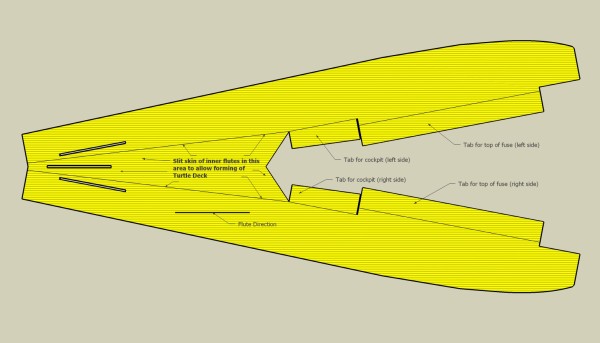 [/link]
See the new image above. The area between the lines in the turtle deck area need the inner skin of the flutes removed so that the coro can be curved over. I used the [link=http://www.spadtothebone.com/misc/hingetool.htm]hinge tool[/link] described on www.spadtothebone.com. You will have to start/stop at mid-flute sometimes because of the angle of the flutes.
See the new image above. There is a weird angle of the flutes for the top of the fuse and cockpit area, but it is possible to score the inside of the coro and bend the coro over in a fairly straight line to form the top of the fuse and cockpit.
Kris
SPAD Twist-VSF assembly instructions - clarification for Fuse steps 1, 4, and 6.
Fuse
1. Cut out the fuse, horizontal stab, and vertical stab 4mil pieces
1. Cut out the fuse, horizontal stab, and vertical stab 4mil pieces
[link=http://www.frostracing.com/RC/07aspadtwist/SPAD%20Twist-VSF%20Fuse-big.jpg]
[/link]This image shows two patterns taped together to make a left and right side.
[link=http://www.frostracing.com/RC/07aspadtwist/800x600/img_0315.jpg]
[/link]This new image is what the resulting piece of coro should look like after cutting it out. click on image to see a larger one for reading instructions.
[link=http://www.frostracing.com/RC/07aspadtwist/flat-fuse-after-cutout-big.jpg]
[/link]
4. Remove the inner flutes in the turtle deck area on the inside of the fuse in a V shaped area. The V is about 1/4” each side of center of the fuse at the back of the fuse to the sides of the turtle deck even with the cockpit.
6. Score and fold the tabs on the V shaped fuse that will become the top of the fuse and cockpit area.
Kris
12-24-2009, 09:02 AM
#14
Junior Member
Join Date: Nov 2008
Location: BroomeWA, AUSTRALIA
Posts: 19
Likes: 0
Received 0 Likes
on
0 Posts
Thanks Kris for taking the time to produce the last drawing - I now understand it. I also realise why you call it a V shaped fuse! I'll work something out with the turtle deck and still finish mine but if I have to build another I'll use you method. Thanks again and Merry Christmas.
04-28-2010, 08:06 AM
#15
Junior Member
Join Date: Nov 2008
Location: BroomeWA, AUSTRALIA
Posts: 19
Likes: 0
Received 0 Likes
on
0 Posts
Hi Kris
Thanks once again for clarifying those points a few months ago. It is built a little bit differently to your plans due to my lack of understanding and the unavailability of square gutterpipe in Australia. Dimensions are the same and it flies very well with my OS 46AX and 12 x 4 prop. I wont post any pictures in your plans as it doesnt look as good as yours!
Cheers Matt
04-28-2010, 11:50 AM
#16
Member
Thread Starter
Join Date: Oct 2004
Location: Lawton, OK
Posts: 53
Likes: 0
Received 0 Likes
on
0 Posts
Glad you got it done and flying!
I have a feeling I probably overlooked some other details in the instructions since I wrote them a while after completing the plane. I have not built a 2nd one following the instructions yet to see what I missed. You have plane #2.
Kris.
I have a feeling I probably overlooked some other details in the instructions since I wrote them a while after completing the plane. I have not built a 2nd one following the instructions yet to see what I missed. You have plane #2.
Kris.
06-08-2010, 12:11 PM
#19
Member
Thread Starter
Join Date: Oct 2004
Location: Lawton, OK
Posts: 53
Likes: 0
Received 0 Likes
on
0 Posts
cool. looking forward to seeing the video.
I don't have any new video of mine since the camera person (the wife) is usually busy since we had a second baby after the SPAD Twist-VSF was completed.
Kris.
I don't have any new video of mine since the camera person (the wife) is usually busy since we had a second baby after the SPAD Twist-VSF was completed.
Kris.
