


Saito FG-60R3
 03-30-2019, 02:20 AM
#2176
Senior Member

I have been doing that for nearly 40 years now.
I do not profess to know evey technical thing there is to know as far as engine maintenance but I do know engine geometry.
 03-30-2019, 04:14 AM
#2177

Join Date: Jan 2007
Location: Dubai, UNITED ARAB EMIRATES
Posts: 500
Likes: 0
Received 2 Likes
on
2 Posts
Sr T, the cylinders are placed 120Deg apart, but the TDC of each cylinder is NOT 120Deg apart, as a result of the crank design, so the TDC's are as follows:
Cylinder 1 at 0Deg on the crank, Cyl 2 TDC is at 126Deg on the crank, Cyl 3 is at 108Deg after that (or 234Deg on the crank) and back to Cyl1, 126 degrees after Cyl 3 to 360Deg on the crank.
So yes, what we are saying is the the TDC's of each cylinder are NOT 120 Deg apart. The Morris ring has the magnets spaced according to the above, all you have to do is time No1 at 30deg BTDC and the others will automatically be inline with what is above.. make sense?
If you consider that previously, the timing magnets from factory are at 120 deg apart exactly, this is already a problem and coupled with the fact that they set the timing at 45 Deg BTDC, this was causing the engine some major problems with ignition variance between the cylinders......it was VERY bad and considering that you could not (from factory), move the hall sensor far enough back to get timing even close to 30deg. I managed 40 Deg, still not good enough.
YES, Morris makes a ring/hub combo with the magnets spaced accordingly for the FG84/90 (they are the same). It is a prob hub with an adjustable ring allowing you to get pretty accurate timing.
Slither, I long suspected that the valve timing would be out, albeit only slightly, but it would make a difference, I brought this up many posts ago, but was hoping (with just a little hope, considering the blundering Saito have managed on these engines) that they would have taken this into account. But they havent. I know it would affect running, but not sure how much. This is disastrous, these engines are a frgging mess, and in my opinion, only good as a nice mounted conversation piece.
Apart from a new crank rod design, it might be worthwile looking into reprofiled cams, but then you would need one for Cyl2 and a diffrent one for Cyl 3. Cyl 1 could possibly stay the same. It would be impossible to just realign the cams by changing a tooth backwards or forwards, because it is quite a coarse gearing...
Engines are rubbish, I am going to sell and move to a UMS, and see if THEY have managed to get it right.....
Ask Ray to pass this information on to the 'brains trust' at Saito and ask them to copy the design Ray has made, and they can make them on their mass production line, sell them to Saito owners at US$50 each, of which US$25 goes to Ray.....but they wont, they have already declared that they 'dont see a problem' and someone would probably have to commit seppuku as a a result of this.... so instead, we will be made to suffer until its time for them to sell us the 'new and improved Saito FG64 Radial engine...
Uurgh..
03-30-2019, 08:35 AM
#2178
Member
Sr T, the cylinders are placed 120Deg apart, but the TDC of each cylinder is NOT 120Deg apart, as a result of the crank design, so the TDC's are as follows:
Cylinder 1 at 0Deg on the crank, Cyl 2 TDC is at 126Deg on the crank, Cyl 3 is at 108Deg after that (or 234Deg on the crank) and back to Cyl1, 126 degrees after Cyl 3 to 360Deg on the crank.
So yes, what we are saying is the the TDC's of each cylinder are NOT 120 Deg apart. The Morris ring has the magnets spaced according to the above, all you have to do is time No1 at 30deg BTDC and the others will automatically be inline with what is above.. make sense?
If you consider that previously, the timing magnets from factory are at 120 deg apart exactly, this is already a problem and coupled with the fact that they set the timing at 45 Deg BTDC, this was causing the engine some major problems with ignition variance between the cylinders......it was VERY bad and considering that you could not (from factory), move the hall sensor far enough back to get timing even close to 30deg. I managed 40 Deg, still not good enough.
YES, Morris makes a ring/hub combo with the magnets spaced accordingly for the FG84/90 (they are the same). It is a prob hub with an adjustable ring allowing you to get pretty accurate timing.
Slither, I long suspected that the valve timing would be out, albeit only slightly, but it would make a difference, I brought this up many posts ago, but was hoping (with just a little hope, considering the blundering Saito have managed on these engines) that they would have taken this into account. But they havent. I know it would affect running, but not sure how much. This is disastrous, these engines are a frgging mess, and in my opinion, only good as a nice mounted conversation piece.
Apart from a new crank rod design, it might be worthwile looking into reprofiled cams, but then you would need one for Cyl2 and a diffrent one for Cyl 3. Cyl 1 could possibly stay the same. It would be impossible to just realign the cams by changing a tooth backwards or forwards, because it is quite a coarse gearing...
Engines are rubbish, I am going to sell and move to a UMS, and see if THEY have managed to get it right.....
Ask Ray to pass this information on to the 'brains trust' at Saito and ask them to copy the design Ray has made, and they can make them on their mass production line, sell them to Saito owners at US$50 each, of which US$25 goes to Ray.....but they wont, they have already declared that they 'dont see a problem' and someone would probably have to commit seppuku as a a result of this.... so instead, we will be made to suffer until its time for them to sell us the 'new and improved Saito FG64 Radial engine...
Uurgh..
Cylinder 1 at 0Deg on the crank, Cyl 2 TDC is at 126Deg on the crank, Cyl 3 is at 108Deg after that (or 234Deg on the crank) and back to Cyl1, 126 degrees after Cyl 3 to 360Deg on the crank.
So yes, what we are saying is the the TDC's of each cylinder are NOT 120 Deg apart. The Morris ring has the magnets spaced according to the above, all you have to do is time No1 at 30deg BTDC and the others will automatically be inline with what is above.. make sense?
If you consider that previously, the timing magnets from factory are at 120 deg apart exactly, this is already a problem and coupled with the fact that they set the timing at 45 Deg BTDC, this was causing the engine some major problems with ignition variance between the cylinders......it was VERY bad and considering that you could not (from factory), move the hall sensor far enough back to get timing even close to 30deg. I managed 40 Deg, still not good enough.
YES, Morris makes a ring/hub combo with the magnets spaced accordingly for the FG84/90 (they are the same). It is a prob hub with an adjustable ring allowing you to get pretty accurate timing.
Slither, I long suspected that the valve timing would be out, albeit only slightly, but it would make a difference, I brought this up many posts ago, but was hoping (with just a little hope, considering the blundering Saito have managed on these engines) that they would have taken this into account. But they havent. I know it would affect running, but not sure how much. This is disastrous, these engines are a frgging mess, and in my opinion, only good as a nice mounted conversation piece.
Apart from a new crank rod design, it might be worthwile looking into reprofiled cams, but then you would need one for Cyl2 and a diffrent one for Cyl 3. Cyl 1 could possibly stay the same. It would be impossible to just realign the cams by changing a tooth backwards or forwards, because it is quite a coarse gearing...
Engines are rubbish, I am going to sell and move to a UMS, and see if THEY have managed to get it right.....
Ask Ray to pass this information on to the 'brains trust' at Saito and ask them to copy the design Ray has made, and they can make them on their mass production line, sell them to Saito owners at US$50 each, of which US$25 goes to Ray.....but they wont, they have already declared that they 'dont see a problem' and someone would probably have to commit seppuku as a a result of this.... so instead, we will be made to suffer until its time for them to sell us the 'new and improved Saito FG64 Radial engine...
Uurgh..
Thanks Cathuga for your post. I think exactly the same thing, but I would not have said it as well since English is only my 3rd language...
A number of craftsmen offer improvements to run this engine, such as Mini Morris Motor in UK or Modelisme Micromoteur Service in France, and probably other ones around the world. That's good, but it's surprising that these improvements do not challenge Saito. Nor the reasons why these improvements are necessary.
To conclude : the transformation of these glow engines into gasoline engines has really failed and specially the radial series,
JM
03-30-2019, 08:12 PM
#2179
Slither, I long suspected that the valve timing would be out, albeit only slightly, but it would make a difference, I brought this up many posts ago, but was hoping (with just a little hope, considering the blundering Saito have managed on these engines) that they would have taken this into account. But they havent. I know it would affect running, but not sure how much. This is disastrous, these engines are a frgging mess, and in my opinion, only good as a nice mounted conversation piece.
Ask Ray to pass this information on to the 'brains trust' at Saito and ask them to copy the design Ray has made, and they can make them on their mass production line, sell them to Saito owners at US$50 each, of which US$25 goes to Ray.....but they wont, they have already declared that they 'dont see a problem' and someone would probably have to commit seppuku as a a result of this.... so instead, we will be made to suffer until its time for them to sell us the 'new and improved Saito FG64 Radial engine...
Uurgh..
Uurgh..
03-30-2019, 11:36 PM
#2180
Join Date: Jan 2007
Location: Dubai, UNITED ARAB EMIRATES
Posts: 500
Likes: 0
Received 2 Likes
on
2 Posts
Slither,
Appreciate the feedback, and pass on thanks to Ray as well. I think everyone here is going to be a little disappointed at the outcome of all of this, and to be honest, I really dont know if I am willing to buy into more effort on these engines. Replacing the main rod on these is not a huge challenge for people in the know, but your average hobbyist is probably not going to go to the effort to do this, and paying money to ship it to someone to do the changes, really does beg as whther the engine is worth it in the first place... I think NOT.
The changes the NEED to be made on this engine are as follows:
New crank
Negative pressure crankcase induction
Prophub with timing ring
Thats a lot of work right there, the engine WILL need to be disassembled, some machining required for induction and main rod as well as the prophub. Make these changes, and you STILL dont know if the quality of the cyl castings will last (I think they are not designed well enough for this purpose.
I include the prophub mod because even WITH the new main rod, you still cannot time these engines at 30Deg as the holes for the hall sensor are placed where they are for the current timing of 45Deg. Either a new prophub or re-drill the holes in the right place. The Morris hub would be a better solution as you could actually make timing changes quite easily if you wanted to.
Also, everytime you remove a cylinder, you would HAVE to replace the cylinder gaskets, and as these are not always available, or sold individually, you would be forced to buy a full gasket set at $30 before shipping...
Its a mess for sure.
I think what I am going to do with mine, is see if I can get it to run reliably enough to get some joy out of it, and then I will retire them when the final ones gives out.
BTW.....if ANYONE has some unused exhaust pipes they would be willing to part with, I would be most interested in buying all/one of them from you.
Regards
03-31-2019, 02:26 AM
#2181
Senior Member
Sr T, the cylinders are placed 120Deg apart, but the TDC of each cylinder is NOT 120Deg apart, as a result of the crank design, so the TDC's are as follows:
Cylinder 1 at 0Deg on the crank, Cyl 2 TDC is at 126Deg on the crank, Cyl 3 is at 108Deg after that (or 234Deg on the crank) and back to Cyl1, 126 degrees after Cyl 3 to 360Deg on the crank.
So yes, what we are saying is the the TDC's of each cylinder are NOT 120 Deg apart. The Morris ring has the magnets spaced according to the above, all you have to do is time No1 at 30deg BTDC and the others will automatically be inline with what is above.. make sense?
https://www.yellowbullet.com/forum/s...d.php?t=490494
A snippet from the above linked article.
"but he did not realize that the piston is on TDC when the centerlines of the crankshaft, crankpin and piston pin are all in alignment. "
To whom it may concern, this occurs at 120* intervals in Saito radial engines.
Last edited by SrTelemaster150; 03-31-2019 at 02:38 AM.
03-31-2019, 02:54 AM
#2182
Senior Member
That is why I asked Morris Mini Motors the question. As of yet, he has failed to answer the question.
I already have a 120* spaced ring for my prototype FA-512R3HC methanol (glow fuel) engine.
I am looking for the proper spaced magnet ring to alter the timing to 35*/29*/41* BTDC ignition advance, or possibly up to 10* more advance for the methanol based fuel.
"but he did not realize that the piston is on TDC when the centerlines of the crankshaft, crankpin and piston pin are all in alignment. "
Last edited by SrTelemaster150; 03-31-2019 at 03:00 AM.
03-31-2019, 02:57 AM
#2183
Senior Member
I am not questioning if it works, obviously it does.
I am questioning the ambiguous timing value nomenclature.
"but he did not realize that the piston is on TDC when the centerlines of the crankshaft, crankpin and piston pin are all in alignment. "
Last edited by SrTelemaster150; 03-31-2019 at 03:01 AM.
03-31-2019, 03:59 AM
#2184
Join Date: Jan 2007
Location: Dubai, UNITED ARAB EMIRATES
Posts: 500
Likes: 0
Received 2 Likes
on
2 Posts
Nothing, I meant the con-rod assembly or whatever you clever engineers call it, but then, you already knew what I was talking about, didnt you?
Just for the record, I find your posts to be rather condescending and makes you appear somewhat petulant. I tend not to get involved in 'heated' discussions on the internet, or messengers for that matter, as one never knows what emotions are contained in a message or forum post, so one person might translate it as aggressive, and another might not. With that in mind, please feel free to post your findings, and pass on any sage advise you may have. Most of us here 'appear' to be the victims of a bad design, intended or not, and would simply like to know if our engines are going to run or not. I think that most discussions here have entailed a lot of people asking questions, proposing solutions and trying to contribute constructively. I hope that continues.
Morris doesn't spend a lot of time on the forums, neither does Ray English to the best of my knowledge, and if Morris hasnt replied to a mail you have sent to his business, you may wish to go down that route, in case he doesnt drop by here soon.
Edit to add: Morris confirms, all rings now have 126-108-126 magnet spacing. I hope this fits the application you want it for...
Last edited by cathurga; 03-31-2019 at 04:50 AM.
03-31-2019, 06:18 PM
#2185
Senior Member
Just for the record, I find your posts to be rather condescending and makes you appear somewhat petulant. I tend not to get involved in 'heated' discussions on the internet, or messengers for that matter, as one never knows what emotions are contained in a message or forum post, so one person might translate it as aggressive, and another might not.
In this particular case I think TDC dwell was being confused with TDC itself. With the slave rod geometry of the Saito 3-cylinder radials, there is a peculiarly long dwell at TDC that lasts for several degrees. The timing values derived from the methods that are used by Morris Mini Motors to time the spark result in ignition timing that is advanced to 30* before the mid-point of that dwell angle. This is as it should be, or damned close anyway. If you read the publication I linked earlier on this thread, it explains why the timing before actual mechanical TDC needs to be varied in radial engines. This is not a “design flaw” on Saito’s part, it is the nature of the beast when dealing with radial engine rod geometry. I don’t think a “mechanical” rod geometry alteration is possible to correct this inherit flaw. Any alteration of the link pin location to correct problems at TDC will most likely cause issues at BDC.
With that in mind, please feel free to post your findings, and pass on any sage advise you may have. Most of us here 'appear' to be the victims of a bad design, intended or not, and would simply like to know if our engines are going to run or not. I think that most discussions here have entailed a lot of people asking questions, proposing solutions and trying to contribute constructively. I hope that continues.
Morris doesn't spend a lot of time on the forums, neither does Ray English to the best of my knowledge, and if Morris hasnt replied to a mail you have sent to his business, you may wish to go down that route, in case he doesnt drop by here soon.
Edit to add: Morris confirms, all rings now have 126-108-126 magnet spacing. I hope this fits the application you want it for...
Edit to add: Morris confirms, all rings now have 126-108-126 magnet spacing. I hope this fits the application you want it for...
OK, now I would like to divulge a little background on my personal experience with CDI systems marketed by C&H Ignitions, RCEXL and Morris Mini Motors. I started doing Saito CDI conversions with glow fuel in the spring of 1997. That was about the time when the 1st C&H Electronics Synchrospark systems were introduced. These were the forerunners of the modern CDI ignition systems with module-controlled timing retard for ease of starting and reliable low RPM performance.
I retain the methanol-based glow fuel for 3 reasons.
1st of all, a methanol fueled Saito engine with CDI can be tuned, with increased compression ratios, up to 7* more ignition timing advance and induction improvements to produce up to 40% more power than a similar displacement gasoline fueled Saito engine.
2nd, methanol runs significantly cooler as well as cleaner than gasoline. Some of my tests have shown a 70F difference in operating cylinder head temperature between methanol and gasoline in Saito engines with CDI.
Last, but not least, Saito engines were designed from the outset to run on methanol-based fuel and were only recently adapted to use with gasoline. IMO, Most of the problems experienced with Saito FG engines are a result of that factor.
So far, I have successfully converted many Saito engines to CDI while retaining the methanol-based glow fuels for the reasons cited above. Those engine types include: FA-91S, FA-100, FA-150, FA-180 including 3 different prototypes with increased compression ratios up to 12.8:1 and/or induction improvements, FA-200Ti and FA-300TTDP. Since my 1st CDI conversion of an FA-150 in 1997 I have abandoned GI (glow ignition) on all of my Saitos save for a brief bout with GI on the FA-91S and the occasional test to compare output and fuel saving in the subsequent conversions. My FA-300TTDP has never turned a propeller with GI.
CDI conversion usually results in a modest increase in power output over GI with similar 15% nitro glow fuel. Usually about 5%. Fuel economy increases by about 25%, but I did see a 70% improvement with the FA-200Ti. That particular engine suffers from a terrible intake flow imbalance that results in uneven fuel distribution. CDI help alleviate the affects of that design flaw.
All other characteristics are similar to gasoline with tremendously improved user friendliness over GI, one flip starts, much lower reliable idle all at significantly lower operating temperatures than gasoline with at least 20% more power output over a gasoline fuel counterpart.
When the FA-450R3 was introduced back in the late 1990s, I was eager to convert one to CDI. Alas, when I inquired as to the feasibility of this several years ago, I was told that the only way to do that was with 3 separate CDI systems, 1 for each cylinder. Not too many years ago I was having one of my frequent phone conversations with Adrian at C&H Ignitions. He was explaining his concept of using a reverse polarity magnet to trigger a sequencing function for the radial engine. This was quite some time before the prototypes were developed. We all know where that lead. He sent me one of his early prototypes for my FA-512R3HC project.
With me experience developing several high compression versions of the FA-180 with CDI/glow fuel, I am developing a high compression methanol version of the FG-84 using an FA-450R3 bottom end with FA-180 cylinders. Except for deck reductions to increase compression ratio, it will be geometrically the same as the FG-84 and the imperial displacement would be 5.12 cu. in. hence the FA-512R3HC designation.
Performance improvements over the FG-84 would include a much higher compression ratio, improved breathing through larger FA-180 valves and a 12mm glow fuel carburetor from the FA-220 Big Bore hop-up kit. Operating temperatures will be much lower and detonation will be less of a factor with methanol-based fuel. I would expect power output to easily top that of the FG-84 by at least 30%. All this will be at the expense of higher fuel consumption but eliminating nitro and reducing the oil content should bring that a little closer to that of gasoline. Cost can be reduced by buying methanol in bulk for less than $2.50 a gallon. That should bring the increased operating cost down to abut 40% over gasoline.
Last edited by SrTelemaster150; 04-01-2019 at 06:21 AM. Reason: typo correction
04-02-2019, 10:32 PM
#2186
Join Date: Jan 2007
Location: Dubai, UNITED ARAB EMIRATES
Posts: 500
Likes: 0
Received 2 Likes
on
2 Posts
SrT, sorry for the late reply, and thanks for 'hanging' out with us mere hobbyists...(that was a joke, not sarcasm, by the way LOL)! I am in the UK at the moment, doing some family matters, and some business as well. I hope to meet up with Morris if I can as we have chatted on messengers, mail and forums, but to meet up in person would be great.
Its an incredibly interesting project you are undertaking, and you will probably end up with a far superior engine than what the manufacturer has put out. Make sure to keep up up to date on your progress, I would like to see the result of what we 'could have' with the right knowledge, tooling and drive!
I hear you on the 'dwell' of the radial engine TDC, and similarly, there MUST be some discrepancy between the TDC dwell of the two 'slave' cylinders and the No1 which is not affected? Or am I grasping at straws. Slither seems to indicate from his discussion with Ray English that it is possible to design a crank that will minimist the effect of geometry, align the valve timing correctly and possibly put this engine in the 'position' it should have been from the start. If it is something that CAN ba done, I will most probably buy into the solution for ONE engine that I own, and see how it all works.
If you think about it, the engine NEEDS the induction conversion (the negative pressure crankcase conversion), it NEEDS the ignition timing to be adjusted and it will probably NEED the main rod conversion. If you had the chance to do this all at once, it would probably cost in the region of US$500 and require an 80% teardown to fit everything, but it would probably work quite well.
I still have some concerns about the thickness and quality of the cylinder walls, as well as the metallurgy used. I am also NOT convinced that the Keleo rings are ideal for these engines, some people claim that they are not an influence, but I am not convinced.
When I am back in Dubai, I will be working on getting the one engine running properly, and will use it as best I can.... then will have to wait and see if RE gets a crank design out that will help....
In the interim, keep up the discussions, findings and experiences here, so that we dont all lose touch.Thanks for all contributions...
04-03-2019, 02:51 PM
#2187
Senior Member
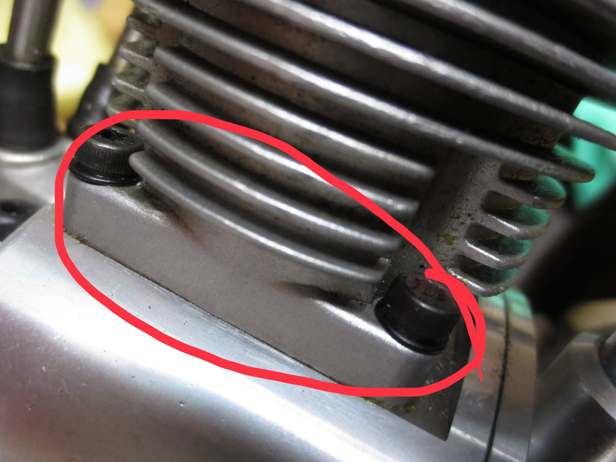
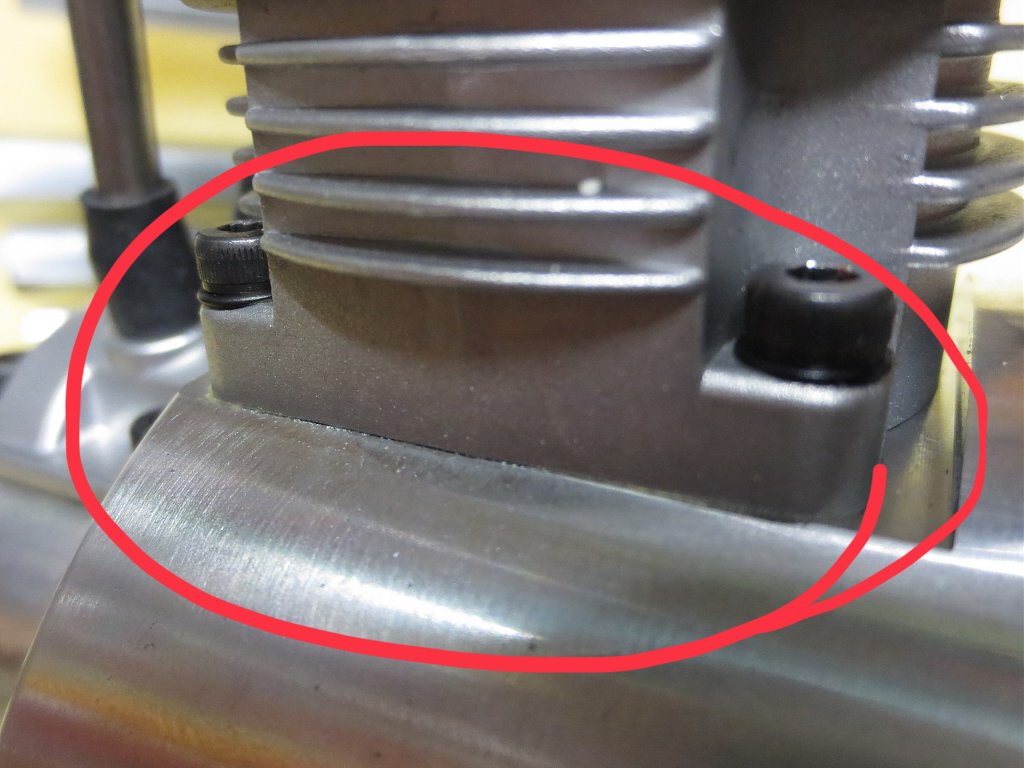
They seems to have changed this.
Old versus new.
04-03-2019, 06:41 PM
#2188
Didier, where did you get that pic of the head? Are these the supplied replacement head? Does this mean if we crack a head that we will have to get all new ones? Are the internal cylinder dimensions the same?? So many questions with just one pic!!! Where can I get these cylinder heads??
Thanks for posting!
MD
Thanks for posting!
MD
04-03-2019, 10:58 PM
#2189
Senior Member
Didier, where did you get that pic of the head? Are these the supplied replacement head? Does this mean if we crack a head that we will have to get all new ones? Are the internal cylinder dimensions the same?? So many questions with just one pic!!! Where can I get these cylinder heads??
Thanks for posting!
MD
Thanks for posting!
MD
No more info available unfortunately.
I checked my engine that I bought late 2018 and found I have the new type cylinderhousing including the new type pistons. So it seems Saito is making the engine slowly better.
04-03-2019, 11:04 PM
#2190
Member
The discussion about valve timing is interesting, but probably has less impact on engine operation than the ignition point. Do not forget that these engines work with low RPM compared to the engine displacement. Sixty years ago Japanese motorcycles engines with this type of engine displacement turned over 20,000 RPM.
Another critical point of this engine is indeed the small thickness of the walls of the cylinder, which even if from the static point of view is enough, is a critical point as far as fatigue is concerned. This point seems to be improved (see Didier's photo). An inside view would be helpfull.
And last point : did anyone really do endurance tests with this engine? Mine fg60r3 has 30 hours of operation, but it's far from enough to say that it's reliable. For example, with 300 hours without issue, I really would say "Now it's good"
JM
04-04-2019, 05:35 AM
#2192
Senior Member
Its an incredibly interesting project you are undertaking, and you will probably end up with a far superior engine than what the manufacturer has put out. Make sure to keep up up to date on your progress, I would like to see the result of what we 'could have' with the right knowledge, tooling and drive!
I hear you on the 'dwell' of the radial engine TDC, and similarly, there MUST be some discrepancy between the TDC dwell of the two 'slave' cylinders and the No1 which is not affected? Or am I grasping at straws. Slither seems to indicate from his discussion with Ray English that it is possible to design a crank that will minimist the effect of geometry,
Since there is no wrist pin offset built into the pistons, there is no appreciable dwell in #1 cylinder. As soon as the piston reaches TDC it reverses direction as the crank journal goes over TDC and the journal with rod start their downward motion relative to the cylinder.
See wrist pin offset affects here.
What is Wrist Pin Offset?
Yes, the slave rods act differently as far as the dwell at TDC. #2 and #3 cylinders act completely opposite from one another. #2 has a trailing affect while #3 has a leading affect. That is why #2 has the ignition timing retarded 6* from the relative position of crankshaft TDC. (126*) and #3 has the ignition time advanced 6* (234*) This is caused by the rocking motion of the link pin bore locations relative to the crank journal bore of the master rod as the crankshaft rotates.
With #2 cylinder, even though the crankshaft and rod have reached TDC and the rod starts a downward travel as soon as the journal passes 120*, the slave rod still has some trailing angle between the link pin location and the wrist pin. This cause the piston to dwell or even rise an imperceptible amount when the rod angle deceases as the crankshaft rotates past TDC. When the rod angle between the link pin and wrist pin are 0*, the crank journal and rod have already started the downward motion well past TDC.. Thus, the dwell has occurred ATDC in #2 cylinder.
#3 cylinder is just the opposite. The rod angle between the link pin and wrist pin are 0* before the crank journal has reached TDC. Now, as the crank journal and rod are still rising as they approach TDC, the slave rod angle increases cancelling out most, if not all of that rise, just the opposite effect as #2 cylinder. Again, we have the piston “dwelling” at TDC, but this time the dwell is BTDC.
Yes, as outlined above, timing to account for piston dwell at TDC is a necessary modification. This is something that has been an integral part of radial engine design for many years. It is something that was missed by the designers of the radial engine CDI concept we use. Saito didn’t catch that when they adopted the design for their gas radial engines.


That could be problematic for the limited crank journal length. While it would most certainly be made to work in the short term, it may not have long term reliability.
It seems that Saito might have addressed that issue with thicker castings for the new cylinders employed on this engine.
Linked slave rod design exists in full scale radial engines and the only design corrections I know of is to ignition advance respective to the various cylinders. Induction systems of the full scale examples are also optimized. There is no variance in cam timing for the respective cylinders that I an aware of.
This may give you some idea of the potential of the CDI/Glow Fuel conversions.
Ths engine is running at an estimated 12.8:1 compression ratio. Much too high for gasoline and it is an ill mannered psychotic prop spitting psychopath when it is fred with GI.
After breaking it in with CDI, I recorded the needle settings, replaced the spark plug with a glow plug, and returned the needles to factory start up settings in an attempt to tune it with GI. I wanted to compare RPM and fuel consumption for the different ignition systems with the same 15% Cool Power glow fuel. After about the 4th or 5th time searching for the double prop nuts and propeller, I gave up on the idea.
With CDI it became a docile, obedient workhorse.
I also did some tests with the 12mm FA-220 Big Bore carburetor and was able to attain 8450 RPM with the 18 X 8 Dynathrust prop and the same 15% glow fuel.. That computes to about 3.44 HP.
Here are some comparisons for the various prototypes for HP and fuel consumption.
https://www.rcgroups.com/forums/show...formance-Gains
https://www.rcgroups.com/forums/show...A180HC-CDI-BBC
This is my FA-300TTDP CDI glow fuel conversion. This engine has never turned a prop with GI.
I believe that the induction, ignition advance and cylinder casting modifications coupled with the use of methanol based fuel would result in the most effective, reliable and powerful prototypes for the FG-60R3 engine.
Last edited by SrTelemaster150; 04-04-2019 at 04:09 PM. Reason: Added Pictures
04-04-2019, 10:25 AM
#2194
Join Date: May 2007
Location: Sherwood,
OR
Posts: 76
Likes: 0
Received 0 Likes
on
0 Posts
F3A Nordic,
I am considering making that purchase also. Please let us know how your motor responds to the new manifold. temps, rpms, carb adjustments, etx.
PS..do you also have the timing ring mod?
Tx Jeff
I am considering making that purchase also. Please let us know how your motor responds to the new manifold. temps, rpms, carb adjustments, etx.
PS..do you also have the timing ring mod?
Tx Jeff
04-04-2019, 12:34 PM
#2195
Join Date: Nov 2003
Location: Linköping, SWEDEN
Posts: 47
Likes: 0
Received 0 Likes
on
0 Posts
Jeff
Yes i did manufacture a new timing ring december 2018 after i had checked timing on this engine on each cylinder.
Did no engine run with saito timing ring due to this timing issue.
Have now run engine for several hour but temp split on each cylinder.
Next step is to run engine with Morris intake kit.
04-04-2019, 02:45 PM
#2196
My Feedback: (24)
Join Date: Aug 2002
Location: Novi, MI
Posts: 884
Likes: 0
Received 0 Likes
on
0 Posts
So after weeks of reading this thread, it appears that the consensus conclusions are that the intake manifold modification and the timing modification are required to make this engine reasonably reliable.
My questions are: 1) Is the Morris' Mini Motors prop hub/magnet ring combo the only commercial solution? 2) If so, is a special puller required to swap this for the stock one (or what was your process for achieving this swap)? and 3) Is the Morris' Mini Motors the only DIY solution for the intake manifold modification?
By the way, this has been a fascinating technical discussion of a very complex set of problems; thanks to all who have participated in it over the years. I do wish everyone (and I do mean everyone) would be a little more careful with their grammar/wording/thought completion/terminology in discussions like this, as a lot of misunderstanding and bickering probably could have been avoided with a little more re-reading and thought before posting. This subject has been complicated enough without having to read between the lines, too.
04-05-2019, 06:00 AM
#2197
My Feedback: (6)
Rick V,
Ray English did my modifications, the ignition timing hadn't been figured out when my engine was purchased and modified. A lot of Ray's internal Modifications have been incorporated by Saito on the more recent production engines.
So My guess is that other than the timing ring (a little less than $100 shipped to the US) is all that you most likely need to get your engine running as well as it can.
I will say that my engine has been running fine and while I have the MMM timing ring yet to install I have a reluctance to do so since it if it ain't broke don't fix it but I think it will happen when the spirit moves me.
Sparky
 04-05-2019, 07:13 AM
#2198
Join Date: Jan 2007
Location: Dubai, UNITED ARAB EMIRATES
Posts: 500
Likes: 0
Received 2 Likes
on
2 Posts
Sparky,
did your RE modification include running the induction through the crankcase?
If not, I would say that on reflection, the 2 most valuable mods anyone could make with these engines, is the negative pressure crankcase inlet mod, along with the timing ring mod. These two changes, on that new engine, would easily result in the best running, and possibly most reliable version of the FG60 R3.
Sparky, I cannot wait to hear your commentary after you have installed and set the MMM timing ring to 30* 😀
04-05-2019, 07:47 AM
#2199
My Feedback: (24)
Join Date: Aug 2002
Location: Novi, MI
Posts: 884
Likes: 0
Received 0 Likes
on
0 Posts
Sparky, thanks for your feedback.
Anyone else, so I can be sure, is this the Morris' timing ring? And for anyone that has installed it, are special tools required?
I should add that my engine was purchased form Horizon in May of 2017. Fairly sure it does not have the updated cylinder castings, any other updates that have been noticed since then?
Last edited by RickVB; 04-05-2019 at 07:49 AM.
04-05-2019, 07:59 AM
#2200
Senior Member
Sparky,
did your RE modification include running the induction through the crankcase?
If not, I would say that on reflection, the 2 most valuable mods anyone could make with these engines, is the negative pressure crankcase inlet mod, along with the timing ring mod. These two changes, on that new engine, would easily result in the best running, and possibly most reliable version of the FG60 R3.
Sparky, I cannot wait to hear your commentary after you have installed and set the MMM timing ring to 30* 😀
did your RE modification include running the induction through the crankcase?
If not, I would say that on reflection, the 2 most valuable mods anyone could make with these engines, is the negative pressure crankcase inlet mod, along with the timing ring mod. These two changes, on that new engine, would easily result in the best running, and possibly most reliable version of the FG60 R3.
Sparky, I cannot wait to hear your commentary after you have installed and set the MMM timing ring to 30* 😀