


Saito FG-60R3


 02-09-2018, 08:09 AM
#1653

Last edited by Fly2XS; 02-09-2018 at 08:15 AM.
02-11-2018, 06:00 AM
#1656

Hello,
Located near La Rochelle, west france, I own a little Company named "MODELISME MICROMOTEUS SERVICE" since 5 years now, and I make a lot "DCi" upgrades on SAITO 60 Radials since several months with full success for European Customers.
The upgrade is named "DCi" for "Direct Crankcase intake" as MOKI and SEIDEL engine by machining the OEM rear intake covers.
- All the internal parts as master & slave rods, ball bearings and bottom pistons are now better lubricated and cooled
- All the 3 cylinders are feed with the same mixture and work at quite same temperature
- the crankcase temperature at full power is 30� Celcius lower than the OEM configuration.
The little hole on the top of the SAITO carburetors has the same function as the hole on the WALBRO metering covers : The mixture is richen or leaned VS atmospehric pressure
So it's very important to delocate this information with a simple nipple and a fuel line behind the firewall in the stabilized air pressure
More informations and photos (where you can see my guys The Cow and The Seagull) on my professional FaceBook webpage :
https://www.facebook.com/ModelismeMicromoteursService/
and on myYoTube channel : https://www.youtube.com/user/eulboyington
02-17-2018, 06:26 PM
#1658

My Feedback: (48)
I too would like more information on what Eulboyinton is doing. I'm not a big fan of Saito's design for the intake system on this engine, and I definitely see the advantage of using the whole crankcase as a plenum such as the Evolution engines. Gotta wonder if it's as simple as opening up the backplate into the crankcase.
02-18-2018, 05:36 PM
#1659
Hello,
Located near La Rochelle, west france, I own a little Company named "MODELISME MICROMOTEUS SERVICE" since 5 years now, and I make a lot "DCi" upgrades on SAITO 60 Radials since several months with full success for European Customers.
The upgrade is named "DCi" for "Direct Crankcase intake" as MOKI and SEIDEL engine by machining the OEM rear intake covers.
- All the internal parts as master & slave rods, ball bearings and bottom pistons are now better lubricated and cooled
- All the 3 cylinders are feed with the same mixture and work at quite same temperature
- the crankcase temperature at full power is 30� Celcius lower than the OEM configuration.
The little hole on the top of the SAITO carburetors has the same function as the hole on the WALBRO metering covers : The mixture is richen or leaned VS atmospehric pressure
So it's very important to delocate this information with a simple nipple and a fuel line behind the firewall in the stabilized air pressure
More informations and photos (where you can see my guys The Cow and The Seagull) on my professional FaceBook webpage :
https://www.facebook.com/ModelismeMicromoteursService/
and on myYoTube channel : https://www.youtube.com/user/eulboyington
Located near La Rochelle, west france, I own a little Company named "MODELISME MICROMOTEUS SERVICE" since 5 years now, and I make a lot "DCi" upgrades on SAITO 60 Radials since several months with full success for European Customers.
The upgrade is named "DCi" for "Direct Crankcase intake" as MOKI and SEIDEL engine by machining the OEM rear intake covers.
- All the internal parts as master & slave rods, ball bearings and bottom pistons are now better lubricated and cooled
- All the 3 cylinders are feed with the same mixture and work at quite same temperature
- the crankcase temperature at full power is 30� Celcius lower than the OEM configuration.
The little hole on the top of the SAITO carburetors has the same function as the hole on the WALBRO metering covers : The mixture is richen or leaned VS atmospehric pressure
So it's very important to delocate this information with a simple nipple and a fuel line behind the firewall in the stabilized air pressure
More informations and photos (where you can see my guys The Cow and The Seagull) on my professional FaceBook webpage :
https://www.facebook.com/ModelismeMicromoteursService/
and on myYoTube channel : https://www.youtube.com/user/eulboyington
05-08-2018, 08:30 PM
#1660
well just found a crack on the no.3 cylinder. I found oil spray in my firewall and thought it was from a leaky exhaust tube. I did 2 short like 2 min ea, no1 spark plug cap came off both times, and landed and the oil spray was back when I checked the plug caps. Came home sorted the loose cap and started looking more closely at where this oil my have come from. The back bolt on the exhaust side had oil all over it. I took the engine off and took the cylinder off. At first I didn�t see anything. Thought maybe it was just a bad gasket. I wiped out the cylinder good and took a bright light and looked over the inside. First I noticed a funky reflection like a broken mirror. I looked more intently and that�s when I found it. Calling horizon tomorrow. 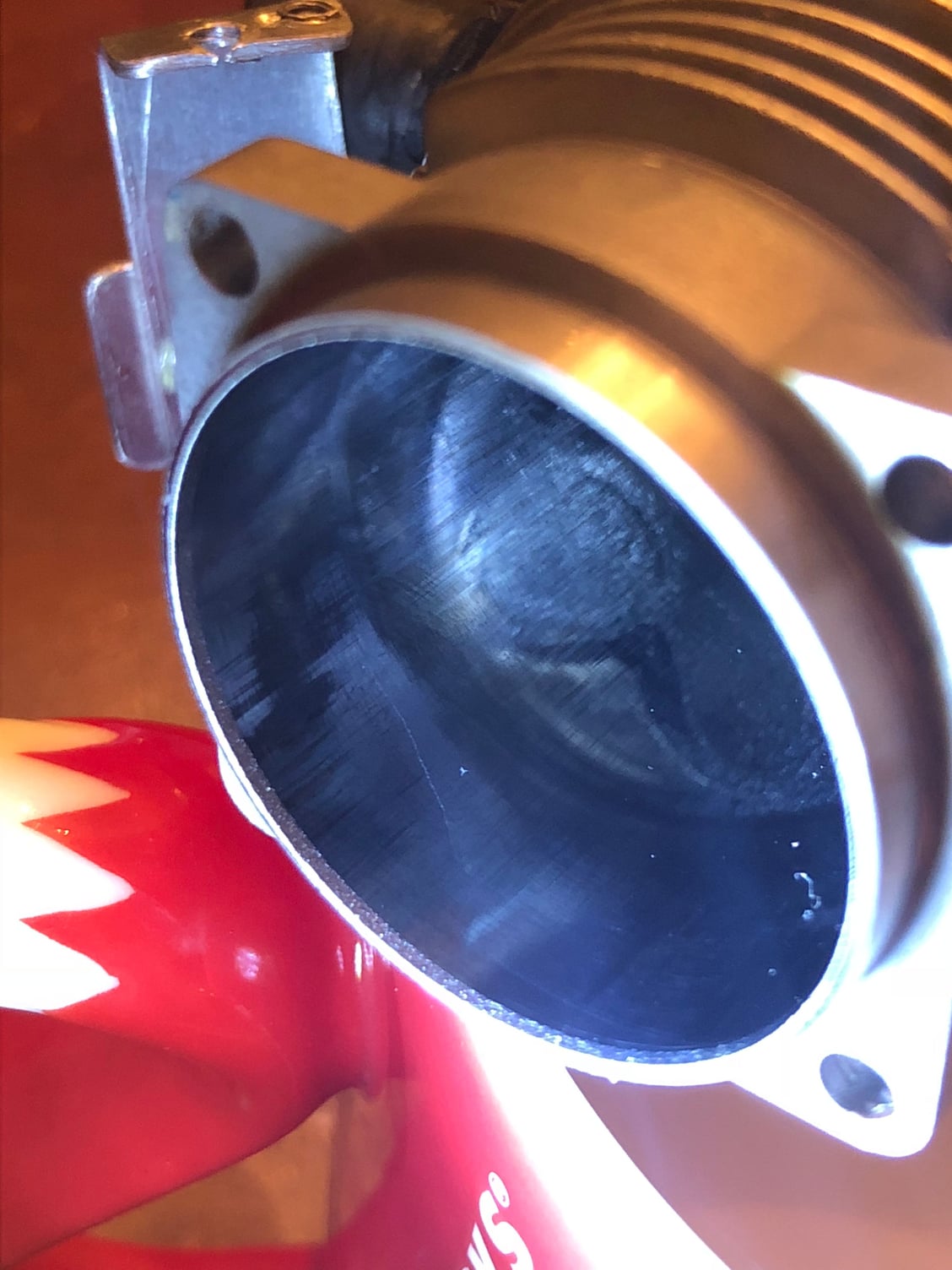

It�s a hairline crack but enough to let oil thru.
It�s a hairline crack but enough to let oil thru.
05-09-2018, 07:53 AM
#1661
I looks like it might be related to stress on the mounting, as it is just inboard of the mounting lug... could it be that the whole area there is weak? Is that normal wear on the cylinder wall? How much time on the engine?
05-09-2018, 02:43 PM
#1662
Senior Member

well just found a crack on the no.3 cylinder. I found oil spray in my firewall and thought it was from a leaky exhaust tube. I did 2 short like 2 min ea, no1 spark plug cap came off both times, and landed and the oil spray was back when I checked the plug caps. Came home sorted the loose cap and started looking more closely at where this oil my have come from. The back bolt on the exhaust side had oil all over it. I took the engine off and took the cylinder off. At first I didn�t see anything. Thought maybe it was just a bad gasket. I wiped out the cylinder good and took a bright light and looked over the inside. First I noticed a funky reflection like a broken mirror. I looked more intently and that�s when I found it. Calling horizon tomorrow.
It�s a hairline crack but enough to let oil thru.
It�s a hairline crack but enough to let oil thru.
05-09-2018, 03:06 PM
#1663
I have an FA-150 jug that has literally had a 55 gallon drum or more of 15% Cool Power glow fuel run through it with CDI, and it isn't as scuffed up as that cylinder. looks to me like the piston was trying to seize, or partially seized momentarily thus putting strain on the cylinder just above the base mounting boss. Is it the top or bottom side of the cylinder.
05-09-2018, 05:39 PM
#1664
Senior Member
I meant top or bottom as viewed from the front or rear. Sorry for the ambiguous question.. I was trying to ascertain how it was oriented as far as the rotation of the crank.
05-09-2018, 08:20 PM
#1665
Not 100% sure about time but this is the last of the three to be replaced. Purchased new on 6/26/2015. The scuffs are from the piston skirt, the top of the cylinder looks like a mirror. This was the back side of cylinder, exhaust side. This is a super zoomed in pic. I can�t feel the scratch�s with my fingernail thay are not that bad. Called horizon talked with a fairly nice rep. Sent me a prepaid shipping label. Last time I had to foot the bill for shipping. I even asked asked for one and was turned down. If I had to guess on the time I would say 15-20 hours total. Which is approximately 90-120 flights. Is average of 30-40 flights per year.
05-10-2018, 05:57 AM
#1666
Senior Member
Not 100% sure about time but this is the last of the three to be replaced. Purchased new on 6/26/2015. The scuffs are from the piston skirt, the top of the cylinder looks like a mirror. This was the back side of cylinder, exhaust side. This is a super zoomed in pic. I can’t feel the scratch’s with my fingernail thay are not that bad. Called horizon talked with a fairly nice rep. Sent me a prepaid shipping label. Last time I had to foot the bill for shipping. I even asked asked for one and was turned down. If I had to guess on the time I would say 15-20 hours total. Which is approximately 90-120 flights. Is average of 30-40 flights per year.
Compare the picture of your cylinder with this FA-150 cylinder with well over 100 hours of flight using methanol/nitro fuel and spark ignition.. The only thing done to it was a thorough cleaning with Dawn Power Dissolver and a Scotch-Brite pad.
05-10-2018, 04:48 PM
#1667
I took it apart again and took better photos. I also got some pics of the piston. The piston tells a story. One that looks like the cylinder walls are too thin and warm up much faster than the block. Where the block is acting like a heat sink and thus keeping the corner tabs cooler as cylinder temps rise. You can see the scuff marks at the corner �area� of the piston. It�s all about temps and thermal expansion. Cylinder walls too thin, final answer. 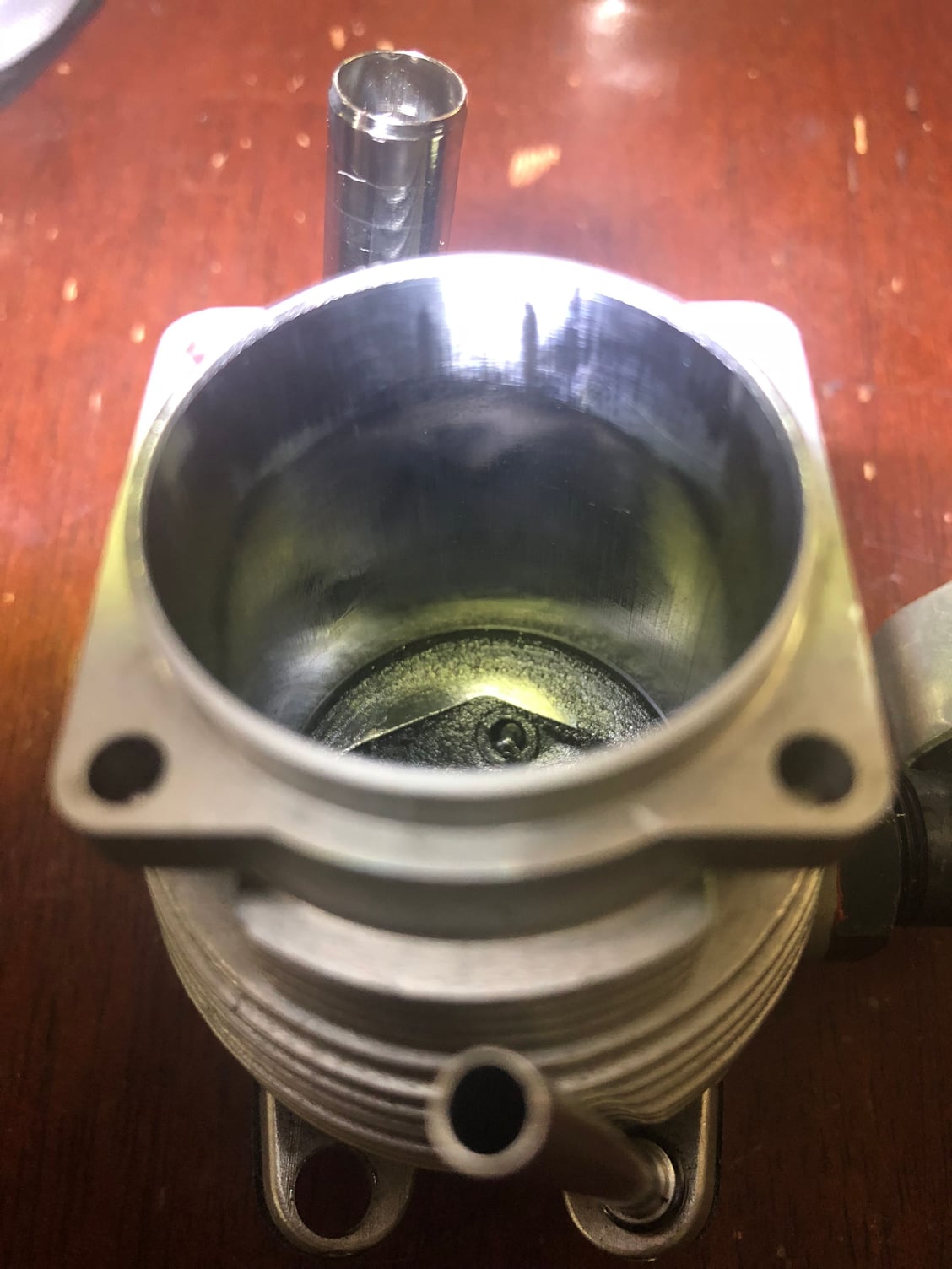


05-11-2018, 04:23 AM
#1668
Senior Member
Rotate the crank until the pin contacts the case and check if there is any clearance on ether side with a feeler gauge. Rotate the crank clockwise as well as counterclockwise. If there are any gaps, check the bore for the link rod pin on the master rod. It looks like it may not be square with the bore and possibly cocking the link rod towards the rear.
The other less likely cause could be the case surface where the #3 cyinder bolts on being machined with a similar cant albeit towards the front.
Here is a similar tool for checking HD rods.
https://www.docshd.com/jims-rod-alig...ductid=7726552
Last edited by SrTelemaster150; 05-11-2018 at 04:27 AM.
05-11-2018, 06:20 AM
#1669
I made this to try and share my thought on the problem. To me it seems that all cylinder failures are occurring at the mounting tabs. I feel that since my no3 cylinder failure only had a crack and not a full separation backs up my thoughts.
05-11-2018, 10:11 AM
#1670
Senior Member
I made this to try and share my thought on the problem. To me it seems that all cylinder failures are occurring at the mounting tabs. I feel that since my no3 cylinder failure only had a crack and not a full separation backs up my thoughts.
https://m.youtube.com/watch?v=MM2fGRTmrWo
https://m.youtube.com/watch?v=MM2fGRTmrWo
You are pointing to the symptom as the cause.
If you think an FG-60R3/FG-21 cylinder is thin at the base, you have never looked at an FA-180/FG-30 cylinder base.
FA-150 on the left, FA-180 on the right.
05-11-2018, 02:47 PM
#1671
Your missing the point here. Tell ya what I�ll get caliper on it so we can get a better understanding. The cylinder wall is not just the part they extrudes past the base. Those look to have 1/3 more thickness than the FG-60. Plus I am pretty sure the FG-21 has a different cylinder. As I tried to fit a FG-20( I know not the exact same) onto the crank case and the �skirt� or �sleeve� that extends past the mounting base was too long and hit the counter weight of the crank shaft.
Basically what I am getting from you is my connecting rod is misaligned. So tell me this, is everyone who has had a failure like this had a misaligned con rod?
Basically what I am getting from you is my connecting rod is misaligned. So tell me this, is everyone who has had a failure like this had a misaligned con rod?
05-11-2018, 06:59 PM
#1673
05-12-2018, 06:19 AM
#1674
Senior Member
It could very well be that all of the failures where because of that.
Last edited by SrTelemaster150; 05-12-2018 at 06:23 AM.
05-12-2018, 07:11 AM
#1675
Senior Member
I took it apart again and took better photos. I also got some pics of the piston. The piston tells a story. One that looks like the cylinder walls are too thin and warm up much faster than the block. Where the block is acting like a heat sink and thus keeping the corner tabs cooler as cylinder temps rise. You can see the scuff marks at the corner �area� of the piston.
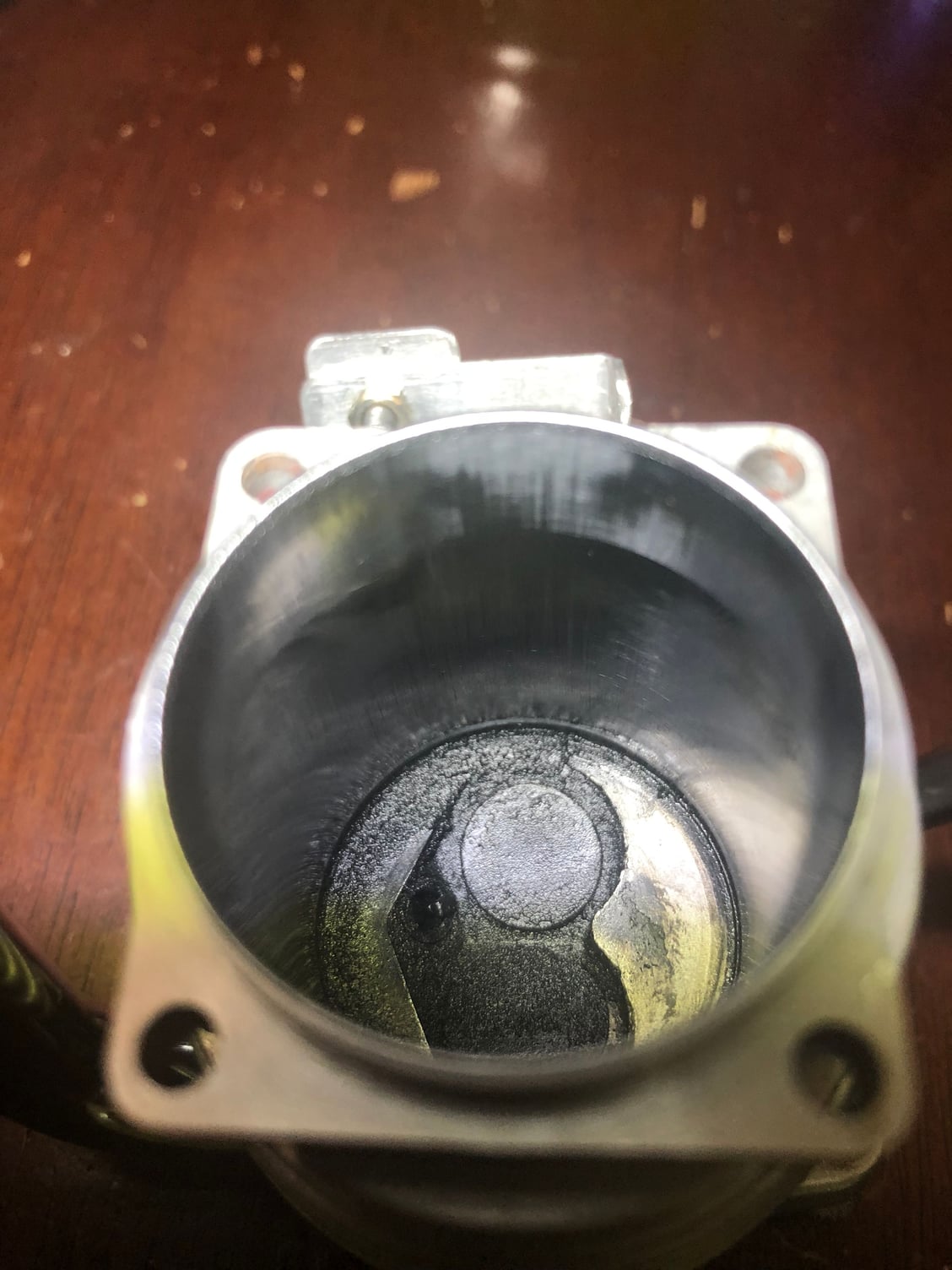
The last time I saw a piston with that cylinder contact pattern was when a friend dismantled an AMF era Harley Davidson big twin engine. That was the result of rod truing being skipped during assembly thus the piston was cocked in the bore. Look at the ring land at the top left of the piston. That portion of the piston should never contact the bore. I would check the trueness of the link rod on that cylinder with a pin the same diameter as the wrist pin but long enough to extend over both sides of the crankcase surfaces where the cylinder base bolts on.
Rotate the crank until the pin contacts the case and check if there is any clearance on ether side with a feeler gauge. Rotate the crank clockwise as well as counterclockwise. If there are any gaps, check the bore for the link rod pin on the master rod. It looks like it may not be square with the bore and possibly cocking the link rod towards the rear.
The other less likely cause could be the case surface where the #3 cyinder bolts on being machined with a similar cant albeit towards the front.
Here is a similar tool for checking HD rods.
https://www.docshd.com/jims-rod-alig...ductid=7726552
Your missing the point here. Tell ya what I�ll get caliper on it so we can get a better understanding. The cylinder wall is not just the part they extrudes past the base. Those look to have 1/3 more thickness than the FG-60. Plus I am pretty sure the FG-21 has a different cylinder. As I tried to fit a FG-20( I know not the exact same) onto the crank case and the �skirt� or �sleeve� that extends past the mounting base was too long and hit the counter weight of the crank shaft.
Basically what I am getting from you is my connecting rod is misaligned. So tell me this, is everyone who has had a failure like this had a misaligned con rod?
Basically what I am getting from you is my connecting rod is misaligned. So tell me this, is everyone who has had a failure like this had a misaligned con rod?
Your piston is cocked in excess of .004" across the distance from the crown to the skirt base in a direction where it should have ZERO misalignment. Don't you think that might be putting significant stress on your cylinder base?
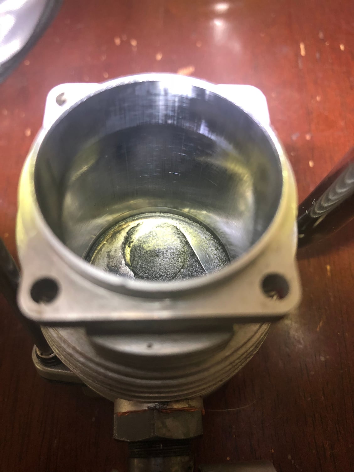
Here are some pictures of an FA-180 piston with in excess of 10 hours time taken from a 12.7:1 compression FA-180 running on glow fuel with CDI. It develops nearly 4 HP with high nitro fuel. Even in that high stress environment, you can see that the bottom of the piston skirt is the only portion in contact with the cylinder wall.
Seems that it is you that is missing the point. I've been building engines for motorcycles and cars for over 50 years and Saito 4-stokes for more than 20. You think the solution is to beef up the cylinder base to withstand the stress imparted by a misaligned piston. Perhaps a better course would be to correct the misalignment first and see what the results are.