


Saito FG-60R3
 12-16-2018, 07:02 PM
#2001

I’d consider doing that if I knew a strobe would pick up a signal through the braid, otherwise the braid would need to be removed and another earth created for the spark, possibly through earthing the engine. I don’t really want to destroy an ignition trying this.
the guesswork regarding the initiation of the hall sensor is gone, confirmed by Adrien and RCExel. The only thing left for ME to do is measure where the lower two cyls TDC is in relation to the magnet, this can be done with a degree wheel and a piston stop.
it may SEEM easier with a timing light but there are other hoops to jump through to do that.
 12-16-2018, 07:57 PM
#2002
Join Date: May 2007
Location: Sherwood,
OR
Posts: 76
Likes: 0
Received 0 Likes
on
0 Posts
So i tested my inductive timing light and it does not read through the wire mesh. I might be able to make an adapter that would go on the spark plug. Then i could read the adapter body.
 12-17-2018, 06:46 AM
#2004
Join Date: Jan 2007
Location: Dubai, UNITED ARAB EMIRATES
Posts: 500
Likes: 0
Received 2 Likes
on
2 Posts
That prop hub is the best option for a stable running engine that won’t smash cylinders. For max power and the best performance would be to get cyl’s 2&3 timed by placing the magnets slight off 120deg.
I will look into that when I’m back from holidays. Not going to do it with a timing light, just by measuring as accurately as possible.
The outer cover on these small plug caps IS the earth, it’s the same for all dle’s and others, the engines with magnetos on them might be different. I have a 30cc buggy that has the engine earthed if I recall, strummers and chainsaws as well, as they don’t need ignition batteries.
With the aero engines, you don’t need to hold the plug to the case to get a spark, the earth is through the braid. Removing it is easy, putting it back is a pain...
as i said earlier, you will also need to make accurate reference marks on the case and hub as well...more hassle than its worth...
12-22-2018, 07:31 AM
#2005
Join Date: May 2007
Location: Sherwood,
OR
Posts: 76
Likes: 0
Received 0 Likes
on
0 Posts
You made my day!! Thank you all for the research and solutions info!
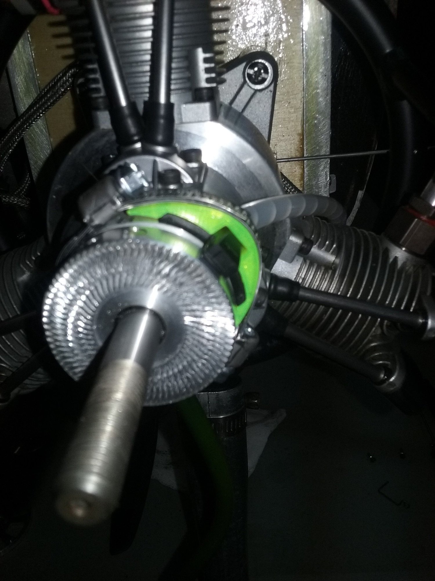
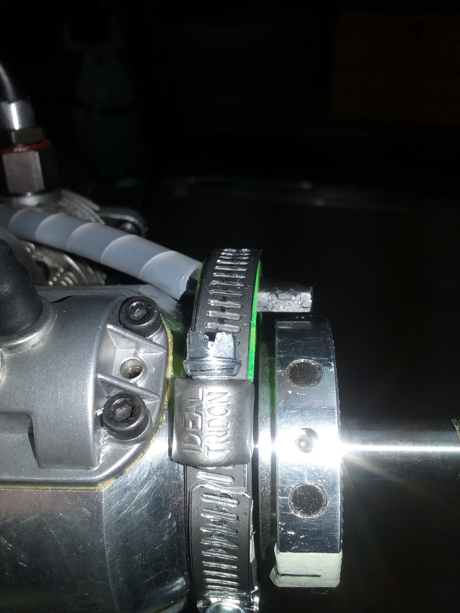
I built an ignition probe-holding adapter that slides to allow for timing adjustment. It is a 3D printed profile part that traps the sensor. Held on with a six mm wide hose clamp. This is a $3 setup for test purposes.
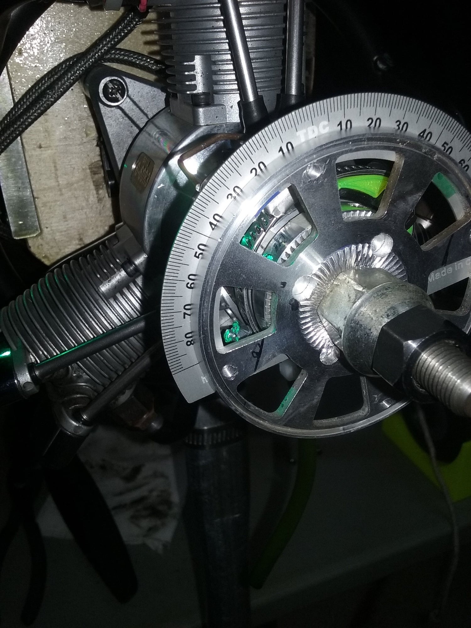
With this setup I adjusted the static timing to 34* btdc on #1.
first flip and it ran nicely at just 3k rpm!! I have always had to do my start and warm-up at 4.5k rpm with the 54* timing for 4 minutes before it would idle down to 2k minimum.
Now it idles steady at 1.5k rpm and will go down to 1.3k for short periods. This is with a room temp of only 40*f.
throttle response was stronger too. it has a 22x8 prop and revs to 6.5k rpm. ( I have a 24x8 to try later).
If the Morrisminor adapter addresses the crankshaft offsets, I will get that setup asap. If not, I'll build an aluminum adapter for a permanent fix.
I can't wait to fly this setup to see how it translates into pulling power!
12-22-2018, 08:06 AM
#2006

Frankly, I don’t see how it is going to prove anything further than what other people have stated. I believe two people have already measured the difference in the timing of cyl’s 2&3. It appears that if the hub timing is 120 deg apart exactly, it causes the timing on 2 to be advanced by 6 deg and retarded by around the same on cyl 3. Going to the trouble of stripping an ignition units cables, creating a negative earth on the engine (plugs don’t have an earth once you’ve remove the sheath) to get a spark and then getting a timing wheel installed to run on the engines, marking all the relevant points to reference the timing light etc, is NOT going to prove anything more than whatever has been proven.
know this though, the timing on this engine is advanced, from the factory, at around 50deg BTDC. This is WRONG.
Aquaskiman, you got rid of all your engines because they all grenaded, right? Do you have any other engines that you have had destroy themselves in this manner? I would like to try and determine whether you have a tendency to abuse/maltreat/misuse engines and I am pretty sure I will not find such a tendency. You operate engines in accordance of manufacturer spec, and the result in all cases but this engine, is that they run well/better without exploding.
the manufacturer of THESE engines used guesswork and statistical deductions to determine spark timing, not scientific methods.
Lets see see how long my engines last, you all get to laugh, point at me and ridicule me when I come back here one day with a pile of scrap. And I WILL report it all to you when it happens.
12-22-2018, 10:08 PM
#2007
Join Date: Jan 2007
Location: Dubai, UNITED ARAB EMIRATES
Posts: 500
Likes: 0
Received 2 Likes
on
2 Posts
Aquaskiman, I assumed as much, you seem to know your way around an engine so it was never in doubt that the FG60 failure was not your fault. It’s a design flaw.
jeff, sounds like an improvement! Nice!
34deg is still a little aggressive, and I cannot compared with mine as they are both at 30deg. The both idle solidly at 1100rpm and the transition is good on both. One is running a 4-blade, the other a 3-blade. Multi blade props usually carry a little more ‘momentum’ so sometimes idle a little better though. The 4-blader in particular, will idle solidly at 950-1000rpm. Maybe yours needs a little leaning up on the low-end, but you should get a solid idle around 1100.
Seems you can tell the the engine is a little ‘happier’ right?
12-23-2018, 02:03 PM
#2008
Join Date: May 2007
Location: Sherwood,
OR
Posts: 76
Likes: 0
Received 0 Likes
on
0 Posts
cathurga, The engine and I are both happier. It is pretty cool here (about 4C) so I think 1200 is about all I can expect until the ambient temp comes up a bit. Number 3 drops out and drops idle below 1000 after about one minute. I am also a little concerned about valve lubrication at such a low idle. the L & H needles seem to be at the optimum since I get a rpm drop when I turn them in either direction. I did try to slightly richen the H and slightly lean the L. but it seems a little softer on the quick throttle opening.
I measured the thrust and with the 22x8 she runs 6500 max and gives 20lb of thrust. With the 24x8, she runs 5500 max and gives 22lb of thrust. with a 19.5lb plane, that will make a nice difference on the slow vertical lines.
FYI, Morrisminer told me he will be able to deliver after the holidays, so I pre-ordered on of his ign rings. FLy well. JJ
01-10-2019, 07:49 AM
#2010
Join Date: May 2007
Location: Sherwood,
OR
Posts: 76
Likes: 0
Received 0 Likes
on
0 Posts
I received an email from Mr Morris saying the timing rings will ship this week. I dont know how long it will take for it to get to US west coast. In the meantime, i am building a cylinder temperature selector setup. Since mt telemetry only has one temp output, i hope to gather some per cylinder temp curves with the 30* timing. If they are still skewed, i will also do the carburator intake mod.
PS...have you run with a larger or shorter exhaust pipe?
PS...have you run with a larger or shorter exhaust pipe?
01-10-2019, 09:05 AM
#2011
Join Date: Jan 2007
Location: Dubai, UNITED ARAB EMIRATES
Posts: 500
Likes: 0
Received 2 Likes
on
2 Posts
LoL!
I can tell you that I have been running the engine in the Sea Fury and have changed the prop from the Biela 18x14 to the VarioProp 18.8x12 (yeah, the vario has odd diameter sizes). It running really well and then all of a sudden had a rough run. When the spark plugs were removed for inspection, one of them just snapped off! The ceramic cake away cleanly from the metal base!
Adjusted valve gaps, they were mostly of butt put them to spec.
Morris is busy with the rings, and is ready to ship out but is now scratching his head as the difference in angular relation of the timing per cylinder has become a bit confusing as there are reports of measurements between engines is different.
I am am going to try get a good measurement on mine tomorrow and was hoping if any of you have measured it, to report back here.
If it is just a few degrees, I think having it 1-5 degrees out is not going to hurt, anything over that could be problematic..
any input appreciated.
all looking good though.
01-10-2019, 11:01 AM
#2012
LoL!
I can tell you that I have been running the engine in the Sea Fury and have changed the prop from the Biela 18x14 to the VarioProp 18.8x12 (yeah, the vario has odd diameter sizes). It running really well and then all of a sudden had a rough run. When the spark plugs were removed for inspection, one of them just snapped off! The ceramic cake away cleanly from the metal base!
Adjusted valve gaps, they were mostly of butt put them to spec.
Morris is busy with the rings, and is ready to ship out but is now scratching his head as the difference in angular relation of the timing per cylinder has become a bit confusing as there are reports of measurements between engines is different.
I am am going to try get a good measurement on mine tomorrow and was hoping if any of you have measured it, to report back here.
If it is just a few degrees, I think having it 1-5 degrees out is not going to hurt, anything over that could be problematic..
any input appreciated.
all looking good though.
I can tell you that I have been running the engine in the Sea Fury and have changed the prop from the Biela 18x14 to the VarioProp 18.8x12 (yeah, the vario has odd diameter sizes). It running really well and then all of a sudden had a rough run. When the spark plugs were removed for inspection, one of them just snapped off! The ceramic cake away cleanly from the metal base!
Adjusted valve gaps, they were mostly of butt put them to spec.
Morris is busy with the rings, and is ready to ship out but is now scratching his head as the difference in angular relation of the timing per cylinder has become a bit confusing as there are reports of measurements between engines is different.
I am am going to try get a good measurement on mine tomorrow and was hoping if any of you have measured it, to report back here.
If it is just a few degrees, I think having it 1-5 degrees out is not going to hurt, anything over that could be problematic..
any input appreciated.
all looking good though.
That was for a single. I imagine that someone can easily design a PIC circuit to allow advance/retard adjustments from the transmitter. I am not capable of writing a single line of code. Doing it with discrete is too inflexible.
01-10-2019, 12:07 PM
#2013

Wow wow
We did not even know all this is going on behind-the-scenes
And yes we have been working on a new prop hub/drive since December
So there are few different version of Saito FG-60 R3 out there
But now we have discovered the rings or not universal to all the FG-60 R3
from now we only can supply rings if you can identify the position of the piston on your engine or if you cannot do that you can send the engine to us to look at
Last edited by Morris Mini Motors; 01-10-2019 at 01:40 PM. Reason: Correct definition
01-10-2019, 01:33 PM
#2014
Join Date: Jan 2007
Location: Dubai, UNITED ARAB EMIRATES
Posts: 500
Likes: 0
Received 2 Likes
on
2 Posts
Welcome Morris! :-)
I dont think there is a problem with the firing order mate, these engines are all firing 1-3-2 according to the manual. At least nobody is reporting that, although a few people have accidentally put the plugs on the wrong way. The problem seems to be that the cylinders are 120 deg apart physically, but the timing points are different due to the nature of the crankshaft design....its either that, or the magnets are not 120 deg apart. (actually havent checked that myself, but will tomorrow!)
With contributions from a few people on here, including Marksp, MDavis, F3A Nordic and Didier; people have determined the following regarding where the timing registers on each cylinders, at the moment we have:
TDC With Cylinder 1 @ 0 degree, cylinder 2 @126 degree, cylinder 3 @ 234 degree. Which gives timing figures around the following:
Timing cyl 1 45,5. Cyl 2. 51. Cyl 3. 39,5. This is as stock Saito timing on one particular engine....
I will measure mine tomorrow as accurately as possible, and let you know.
Regards
01-10-2019, 01:48 PM
#2015
OK
We have new ring setup with magnet set at 120 degrees apart
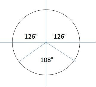
Also we will have magnet rings with #1 to #2 magnet at 126 degrees and #2 to #3 magnet at 108 degrees and #3 to #1 magnet at 126
We have new ring setup with magnet set at 120 degrees apart
Also we will have magnet rings with #1 to #2 magnet at 126 degrees and #2 to #3 magnet at 108 degrees and #3 to #1 magnet at 126
Last edited by Morris Mini Motors; 01-11-2019 at 05:58 AM.
01-11-2019, 03:06 AM
#2016
Join Date: Jan 2007
Location: Dubai, UNITED ARAB EMIRATES
Posts: 500
Likes: 0
Received 2 Likes
on
2 Posts
Hey All,
Did some measuring today, and this is what I got. It seems consistent that the angles between the master and slaves is the same on both sides, and it seems the angle between the slaves is a little narrower. I hope this is correct, and it would work properly.
I really dont know, from an engineeering perspective, whether this is an optimal design or not. I would have thought, with the cylinders at 120deg apart, the crank position timing would need to be the same.
Morris, thank you for all your help mate, I know its really frustrating but you are an asset to the hobby, and we are grateful for your effort. I would be happy to test a 120Deg ring and one with angles of 126/108/126. I dont mind being a guinea pig on this, so get some rings built up and send 'em over! :-)
Regards
01-11-2019, 09:43 AM
#2017
Join Date: Nov 2003
Location: Linköping, SWEDEN
Posts: 47
Likes: 0
Received 0 Likes
on
0 Posts
Hello
I have made a new prop hub based on my check of timing on My new engine.
Have used Proxxon dividing attachment 24264 to drill Hole for each magnet.
My goal was to have timing each cylinder within 1 degree and i almost made it, it is now
cylinder 1 30 degree, cylinder 2 30,5 degree and cylinder 3 31,5 degree.
I did borrow a lathe and bought dividing attachment and i am happy with the result with this cheap tools used.
Have started the engine and made brake in run and started to lean it but have not been possible
to have same temp on all cylinder and have turned engine during brake in to lean cylinder 2 and 3.
Next step is to buy intake kit from Morris mini motor .
The goal with all this is to have a engine that don't brake down and you can use for long time with normal maintenance.
Are now traveling and working and have to wait to be back at home for more test of engine.
01-11-2019, 11:56 AM
#2018
Join Date: Jan 2007
Location: Dubai, UNITED ARAB EMIRATES
Posts: 500
Likes: 0
Received 2 Likes
on
2 Posts
Great news Nordic, and I am sure with that setup it will be a good, solid engine. Would you mind sharing with us what the spacing is on the magnets in degrees? Morris is doing for us, what you were able to do on your own and I would be VERY happy with the setup you have.
With regards to the break in process, it is necessary to rotate the engine, or at least run it inverted in order to get all the cylinders some HOT time, so just proceed the way you are, I would think that everything will be good.
Thanks for the feedback.
With regards to the break in process, it is necessary to rotate the engine, or at least run it inverted in order to get all the cylinders some HOT time, so just proceed the way you are, I would think that everything will be good.
Thanks for the feedback.
01-12-2019, 04:53 AM
#2019
Join Date: Nov 2003
Location: Linköping, SWEDEN
Posts: 47
Likes: 0
Received 0 Likes
on
0 Posts
Hello again
Cartuga
Spacing #1 to #2 magnet 126 degree. Spacing #2 to #3 magnet 108 degree. Spacing #3 to #1 magnet 126 degree.
I think this is correct Spacing but due to my cheap tool during manufacturing i have 1,5 degree off but are happy with it.
Cartuga
Spacing #1 to #2 magnet 126 degree. Spacing #2 to #3 magnet 108 degree. Spacing #3 to #1 magnet 126 degree.
I think this is correct Spacing but due to my cheap tool during manufacturing i have 1,5 degree off but are happy with it.
01-14-2019, 02:02 AM
#2021
Join Date: Jan 2007
Location: Dubai, UNITED ARAB EMIRATES
Posts: 500
Likes: 0
Received 2 Likes
on
2 Posts
Jeff,
i dont think there is a need to identify them. We know that some versions had some differences, but it appears that the crank angles are consistent so you would be good to go with the ring/hub combo that Morrise is building. I think we have ascertained that the firing order has NOT changed. It’s all 1-3-2.
As far as I know, some of the very earliest models didn’t have a brass bush on the crank, but I haven’t seen any. Maybe I should trawl the earlier threads to see if someone had this setup. From what I see, the problems with the FG-84 were resolved and passed on to the 60 (apart from the aggressive timing of course). The only change that I KNOW of seems to be the redesigned pistons.
get the new hub, time it to around 30-32deg and you should have a good engine.
01-14-2019, 11:14 PM
#2024
Join Date: Jan 2007
Location: Dubai, UNITED ARAB EMIRATES
Posts: 500
Likes: 0
Received 2 Likes
on
2 Posts
Thanks Didier, I think we are agreed that this is consistent throughout the range.
I am sure the morris hubs will help us to get the timing as close to even as we can get. Someone also pointed out that there might be some differences in magnet strengths etc etc, but it appears to me that these factors will not create a huge problem
I am sure the morris hubs will help us to get the timing as close to even as we can get. Someone also pointed out that there might be some differences in magnet strengths etc etc, but it appears to me that these factors will not create a huge problem