MR Aerodesign 1/4 Scale Mudry CAP 10b Review / Build
 06-11-2009, 07:40 PM
#26

Thread Starter
My Feedback: (4)
Join Date: Mar 2002
Location: redwood city,
CA
Posts: 127
Likes: 0
Received 0 Likes
on
0 Posts
Day 8...
So I went with Bipeman's idea and will run 10-32 rod through the engine, standoffs, box, all the way through the firewall. This has the added advantages of maintaining the strength of the firewall and allowing more adjustability or even changing the engine in the future.
After measuring a million times and cutting all the parts, make sure they are a nice snug fit. Temorarally clamp the box together and make triangle stock parts for all the internal corners. MAKESUREITASSQUAREALLAROUND.
I used 30min epoxy, and glued it all at once. Using my handy panes of glass, the bag lead and a few rubberbands. a quick check with the square let it set for a good hour.
I removed a sectoin of cowl ring to allow the box to fit against the firewall.....And voila...we hava box. <input type="hidden" id="gwProxy" /><input type="hidden" onclick="jsCall();" id="jsProxy" />
I will pin the front of the box later. Now its time for a vino and movie with the family....<input type="hidden" id="gwProxy" /><input type="hidden" id="jsProxy" onclick="jsCall();" /><input type="hidden" id="gwProxy" /><input type="hidden" onclick="jsCall();" id="jsProxy" /><input type="hidden" id="gwProxy"></input><input type="hidden" id="jsProxy" onclick="jsCall();" />
So I went with Bipeman's idea and will run 10-32 rod through the engine, standoffs, box, all the way through the firewall. This has the added advantages of maintaining the strength of the firewall and allowing more adjustability or even changing the engine in the future.
After measuring a million times and cutting all the parts, make sure they are a nice snug fit. Temorarally clamp the box together and make triangle stock parts for all the internal corners. MAKESUREITASSQUAREALLAROUND.
I used 30min epoxy, and glued it all at once. Using my handy panes of glass, the bag lead and a few rubberbands. a quick check with the square let it set for a good hour.
I removed a sectoin of cowl ring to allow the box to fit against the firewall.....And voila...we hava box.
<input type="hidden" id="gwProxy" /><input type="hidden" onclick="jsCall();" id="jsProxy" />I will pin the front of the box later. Now its time for a vino and movie with the family....<input type="hidden" id="gwProxy" /><input type="hidden" id="jsProxy" onclick="jsCall();" /><input type="hidden" id="gwProxy" /><input type="hidden" onclick="jsCall();" id="jsProxy" /><input type="hidden" id="gwProxy"></input><input type="hidden" id="jsProxy" onclick="jsCall();" />
 06-16-2009, 07:13 PM
#27
Thread Starter
My Feedback: (4)
Join Date: Mar 2002
Location: redwood city,
CA
Posts: 127
Likes: 0
Received 0 Likes
on
0 Posts
Day 9..
Oh Crap!!
I neglected to make room for the muffler. No problem, a glass of ruby vino to lubricate the old brain and a simple solution was found.
Simply cut a notch.
I have no saw with a long enough blade, so a quick trip to Bipeman's house to use his saw and a step was cut. I re-enforced it wit h1/8" and 1/4" play and away we go. problem solved.
Ia frame of 1/4" tri-stock help alighn the box on the firewall and now the holes can be drill for the threaded rod to pass all the way through.
It all lines up perfectly.
<input type="hidden" id="gwProxy" /><input type="hidden" onclick="jsCall();" id="jsProxy" /><input type="hidden" id="gwProxy" /><input type="hidden" id="jsProxy" onclick="jsCall();" />
<input type="hidden" id="gwProxy" /><input type="hidden" onclick="jsCall();" id="jsProxy" /><input type="hidden" id="gwProxy" /><input type="hidden" id="jsProxy" onclick="jsCall();" /><input type="hidden" id="gwProxy" /><input type="hidden" onclick="jsCall();" id="jsProxy" /><input type="hidden" id="gwProxy"></input><input type="hidden" id="jsProxy" onclick="jsCall();" />
06-16-2009, 11:04 PM
#28
Thread Starter
My Feedback: (4)
Join Date: Mar 2002
Location: redwood city,
CA
Posts: 127
Likes: 0
Received 0 Likes
on
0 Posts
It's time to look at the tail feathers.
I started by making sure all the parts were there. Now a good study of the plans are needed. Not a lot of hepl here so this may take a little longer than planned.
There seems to be a mismatch. No E6a and two E7s, one balsa one ply. totally different shapes.. I'll Have to think about that one
 <input type="hidden" id="gwProxy" /><input type="hidden" onclick="jsCall();" id="jsProxy" /><input type="hidden" id="gwProxy"></input><input type="hidden" id="jsProxy" onclick="jsCall();" />
06-19-2009, 11:45 AM
<input type="hidden" id="gwProxy" /><input type="hidden" onclick="jsCall();" id="jsProxy" /><input type="hidden" id="gwProxy"></input><input type="hidden" id="jsProxy" onclick="jsCall();" />
06-19-2009, 11:45 AM
#29
Thread Starter
My Feedback: (4)
Join Date: Mar 2002
Location: redwood city,
CA
Posts: 127
Likes: 0
Received 0 Likes
on
0 Posts
Figured I better do this before I forget....
The firewall is now pinned with 1/8" dowel and reinforced inside with tri-stock, the engine box does not need to be pinned as the whole assebly will be clamped by the monting bolts (stainless threaded rod) that will go from the front right through the firewall.
I also trimmed and replaced the cowel ring and spacer pieces I had cut out earlier to clear the box.
<input type="hidden" id="gwProxy" /><input type="hidden" id="jsProxy" onclick="jsCall();" /><input type="hidden" id="gwProxy" /><input type="hidden" onclick="jsCall();" id="jsProxy" /><input type="hidden" id="gwProxy"></input><input type="hidden" id="jsProxy" onclick="jsCall();" />
06-19-2009, 07:41 PM
#30
Thread Starter
My Feedback: (4)
Join Date: Mar 2002
Location: redwood city,
CA
Posts: 127
Likes: 0
Received 0 Likes
on
0 Posts
Day 10....
Tailplane
The elevators are pretty straight forward although I decided to build them upside down instead on using the tabs. As it is a simetrical structure, the only tricky part is lining up the tips with the tailplane. I will be adding the tips later instead so they can be aligned then.
I will be using hing pints so i put blocks of bals inside at the hinge locations on both elevators and tailplane.
This way you can shape the hinge beval without anything in the way.
The tailplane was built up using the guide on the plane. this works well. the 3/32 play spars are not provided so i cut them from the sprue leftover form some of laser cut sheets. The bottom spar is not flat so shim it up as you attach the ribs, moving from the middle out.
I could not figure out the way MR wants to do the tip diagonals so I used extra block balsa instead.
Don't forget the sheer webbing this is vital to the strength of this structure.
Sheet the top and sand smooth all around including the tips.
Before I removed the tailplane form the bench to do the bottom, i jigged up the elevators making sure the rear edges are exactly leval. After cutting the tip blocks to the fianl round shape I lined them up and glued in place on the elevators. Then I added the additional digonal blocks.
Shape the tips as closely as possible so that you can use the top side as guide for shaping the bottom part of the tips.
After a lot of planing and sanding, the tailplane can be removed from the plan and the tabs removed and the structure sandinded smooth.
Apply the bottom sheeting making sure not to twist the structure.
Fit the elevators to the structure and wit hthe top edge nicely lind up, mark the bottom shape and plane/ sand to a nice fit.
Add the 1/4" leading edge and shap it to a nice aerofoil.
A final sand and you done.
The gap between the hindge beval and the diaganol block will be filled later.
Its starting to look less like a canoe!!!
<input type="hidden" id="gwProxy" /><input type="hidden" onclick="jsCall();" id="jsProxy" /><input type="hidden" id="gwProxy"></input><input type="hidden" id="jsProxy" onclick="jsCall();" />
06-21-2009, 10:25 PM
#31
Thread Starter
My Feedback: (4)
Join Date: Mar 2002
Location: redwood city,
CA
Posts: 127
Likes: 0
Received 0 Likes
on
0 Posts
Day 11....
Rudder:
First I drilled out the ply ribs. They seemed a little heavy so a few holes looses the wieght and maintains the strength.
Cut the leading edge sheet for both sides. Use the plans for a template.
Cut two pieces of 1/4" balsa the right length and 1 1/2" wide for the leading edge.
Pin one piece of 1/4 leading edge down to the plan and glue the ribs to it, tabs down. It is impossible to pin throught the plywood so I use my handy bag O lead to wieght the structure down to the bench. Then add the top sheeting, but dont glue the front edge yet. The tip rib R1 has no tabs and positioning it with the the sheeting, still movable, will be easier.
Remove the structure from the plan, turn over and remove the front tabs ONLY. The 1/4" leading edge piece is now your front jig.
Add the bottom sheeting (due not glue the front edge) then turn back over.
Use the wieghts again to hold the structure flat. add the shear webbing, this will lock in the shape of the rudder.
Add the trailing adge pieces.
Cut some 3/32" plywood from scrap, for the control horn doublers, and glue in place.
Add the tip rib R1 and now glue both top and bottom leading edge sheeting joints sandwitching all in place.
Remove the whole assembly form the plans, remove the rear tabs and sand the rudder shape using the natural contours from front to back.
Add the second layer of 1/4" leading edge sheet and sand to shape. Also add the bottom piece of 1/4" to fill the gap at the bottom.
Sand the hinge bevel at this point. it will be hard to do when the tip block is attached.
We will add the tip and bottom blocks later so we can shape them to the fin.
The is a very ridged structure..Nice...Time for some vino...
<input type="hidden" id="gwProxy" /><input type="hidden" onclick="jsCall();" id="jsProxy" /> <input type="hidden" id="gwProxy" /><input type="hidden" id="jsProxy" onclick="jsCall();" /> <input type="hidden" id="gwProxy" /><input type="hidden" onclick="jsCall();" id="jsProxy" /> <input type="hidden" id="gwProxy"></input><input type="hidden" id="jsProxy" onclick="jsCall();" />
Rudder:
First I drilled out the ply ribs. They seemed a little heavy so a few holes looses the wieght and maintains the strength.
Cut the leading edge sheet for both sides. Use the plans for a template.
Cut two pieces of 1/4" balsa the right length and 1 1/2" wide for the leading edge.
Pin one piece of 1/4 leading edge down to the plan and glue the ribs to it, tabs down. It is impossible to pin throught the plywood so I use my handy bag O lead to wieght the structure down to the bench. Then add the top sheeting, but dont glue the front edge yet. The tip rib R1 has no tabs and positioning it with the the sheeting, still movable, will be easier.
Remove the structure from the plan, turn over and remove the front tabs ONLY. The 1/4" leading edge piece is now your front jig.
Add the bottom sheeting (due not glue the front edge) then turn back over.
Use the wieghts again to hold the structure flat. add the shear webbing, this will lock in the shape of the rudder.
Add the trailing adge pieces.
Cut some 3/32" plywood from scrap, for the control horn doublers, and glue in place.
Add the tip rib R1 and now glue both top and bottom leading edge sheeting joints sandwitching all in place.
Remove the whole assembly form the plans, remove the rear tabs and sand the rudder shape using the natural contours from front to back.
Add the second layer of 1/4" leading edge sheet and sand to shape. Also add the bottom piece of 1/4" to fill the gap at the bottom.
Sand the hinge bevel at this point. it will be hard to do when the tip block is attached.
We will add the tip and bottom blocks later so we can shape them to the fin.
The is a very ridged structure..Nice...Time for some vino...
<input type="hidden" id="gwProxy" /><input type="hidden" onclick="jsCall();" id="jsProxy" />
07-05-2009, 10:55 AM
#32
Thread Starter
My Feedback: (4)
Join Date: Mar 2002
Location: redwood city,
CA
Posts: 127
Likes: 0
Received 0 Likes
on
0 Posts
Day 12...
Fin (vertical stab.), and Ailerons
Fin:
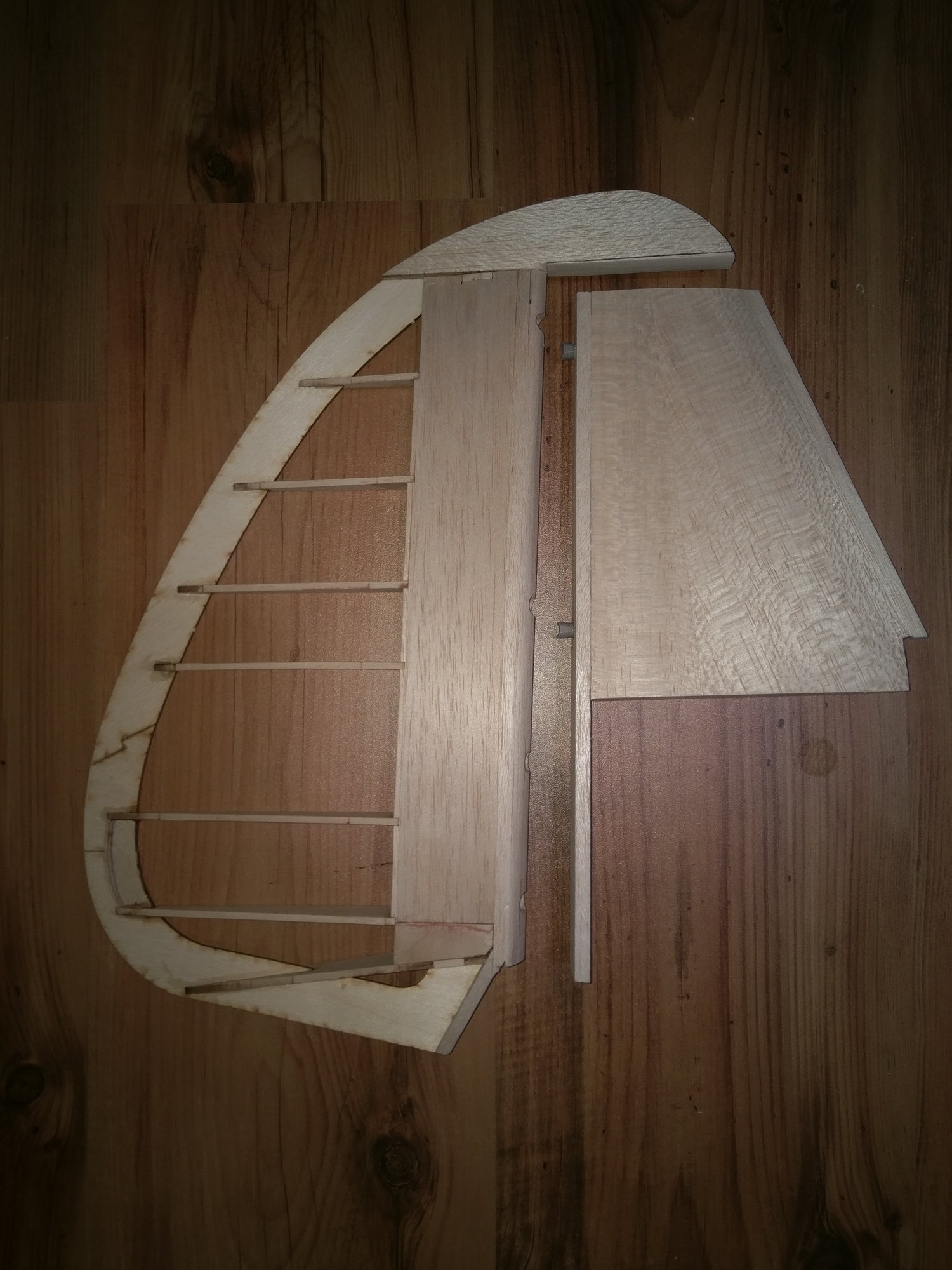
This is made in the same way as the tailplane was. Using 1/4" x 1" stock trailing edge as a guide, and the tabs on the ribs facing down. Attach all the ribs to the traing edge.
Cut some 3/32 x 1/2" play spars from scrap (they are not provided) and glue the top spar in place making sure all the tabs are flat on the board.
Add the 3/32" balsa leading edge and sand down to the rib edges.
Add the top sheeting then sand it flush with the the leading
Remove form plan and turn upside down. Now you can remove the tabs and sand the trailing and leading edge down to the rib level.
Add the sheer webbing and hinge blocks as needed.
Add the sheeting and leading edge 1/4" stock than sand the whole thing to shape...
Hold the finished structure up to the fin and make sure the tops are even. Add the Rudder tip block to the rudder and sand to match the contours of the fin tip.
Fin (vertical stab.), and Ailerons
Fin:
This is made in the same way as the tailplane was. Using 1/4" x 1" stock trailing edge as a guide, and the tabs on the ribs facing down. Attach all the ribs to the traing edge.
Cut some 3/32 x 1/2" play spars from scrap (they are not provided) and glue the top spar in place making sure all the tabs are flat on the board.
Add the 3/32" balsa leading edge and sand down to the rib edges.
Add the top sheeting then sand it flush with the the leading
Remove form plan and turn upside down. Now you can remove the tabs and sand the trailing and leading edge down to the rib level.
Add the sheer webbing and hinge blocks as needed.
Add the sheeting and leading edge 1/4" stock than sand the whole thing to shape...
Hold the finished structure up to the fin and make sure the tops are even. Add the Rudder tip block to the rudder and sand to match the contours of the fin tip.
07-05-2009, 10:58 AM
#33
Thread Starter
My Feedback: (4)
Join Date: Mar 2002
Location: redwood city,
CA
Posts: 127
Likes: 0
Received 0 Likes
on
0 Posts
Ailerons:
These are very simple. although you have to be careful to cut the top and bottom sheeting trailing edge shape to match the pre-cut ABF trailing edge parts. If you do not do this they are very difficult to cut to fit later.
Build both at once to make sure you get a left and right aileron!!!
Pin you bottom sheeting on the plan attach TE part ABF and glue all the ribs using the plan and a guide. I checked with MR and they should be built flat to the board.
Again I have added balsa block for hinge points. make sure you put in the ply reinforcements for the control horns. these must be cut from scrap 3/32 ply.
Add the Top sheet and sand the whole thing smooth.
Mark a center line in the leading edge and carefully bevel the edge.
07-05-2009, 11:09 AM
#34
Thread Starter
My Feedback: (4)
Join Date: Mar 2002
Location: redwood city,
CA
Posts: 127
Likes: 0
Received 0 Likes
on
0 Posts
Day 13:
Wing.
First punch out all the parts and make sure they are all there. I noticed that I was missing a W1 front section and all the 3/32" x 1/4" spars. I called MR. The sticks were a shipping mistake and he is taking care of it. The missing W1 is a plan problem, it is not even on the laser template. However, there are an extra W3B2 and a W1 can be easily fabricated form that!!!! cool. I also notice the wing hold down plate was too wide so that will be cut down to match the openings in the ribs.
Center Section
:.
First I laminated the main spar using 2hr epoxy to make sure it is as strong as can be.
Then manufactured the missing W1 front piece form the extra W3B2
07-07-2009, 06:35 PM
#35
Thread Starter
My Feedback: (4)
Join Date: Mar 2002
Location: redwood city,
CA
Posts: 127
Likes: 0
Received 0 Likes
on
0 Posts
Day 14
Center Section continued
To make the spars, cut and laminate 2 pieces of 3/16 x 1/2" to exactly the length on the plan. Make two these.
Glue the bottom spar to the base of the main dihedral brace. make sure this is exactly centered. this forms a good frame to start cluing the rest of the ribs to.
Test fit and glue all the center section ribs to the main spar assemble. Glue the bottom secondary dihedral brace in at this time make sure they are all square.
Note: One of the tip ribs was very warped so through this process I kept it straight with a clamp and piece of hardwood. Once the sheeting was on that could be removed.
Install the top spar and top secondary dihedral braces and again make sure all is square.
Add 1/4" in spars
Add the top sheet up to the middle of the main spar.
Attach tri stock to all the front ribs and carefully attach them to the from of the dihedral brace.
Install 3/32" leading edge backing then install front leading edge sheet and sand level with the front edge.
Remove form plan.
Attach the 1/4" leading edge and carefully mark a center line for the wing dowels.
Drill the dowel holes then shape the leading edge to match the rib edge.
Install the wing hold down plate.
Don not remove the tabs or sheet the bottom yet.
07-07-2009, 09:54 PM
#36
Thread Starter
My Feedback: (4)
Join Date: Mar 2002
Location: redwood city,
CA
Posts: 127
Likes: 0
Received 0 Likes
on
0 Posts
Left Wing
Prepare the angle of the center section:
With a bit of geometry, knowing the length of the center section and that the dihedral angle is 6 degrees, we can calculate how much to raise the right hand end. Mine come out about 1.2"
As the plywood tabs are hard to pin, I secured the center section with my trusty bag of lead!
First laminate the main spars form 3/6" x 1/2" basswood, noticing where they go from double layer to single layer.
Test fit all the ribs and rib assemblies.
I noticed a problem here:
W3A is not cut at all correctly and you need to us on of the neighboring ribs as a template to make it fit correctly. See picture.
Use the assembled flap hinge/hangers to gauge the width of the supporting ribs and tack glue the supports in place.
Now slide all the pieces to the assembly and glue with 30min epoxy. Make sure to keep everything square and not to get any extra glue in the flap hing boxes or the landing gear block area.
We can now glue in the top spar with 30min epoxy.
Working form the root to the tip add all the other ribs, glue the top spar first then carefully raising the bottom spar to meet the rib, pinning the structure down as you go.
Add the 1/4" square balsa spars and the the sheer webbing.
Sand the leading and trailing edges of the ribs even and add the 3/32" balsa leading edge and sand to shape.
Add the 1/4" balsa training edge and sand top edge to shape.
Carefully sand the structure to make sure all the spars are level wit the ribs and start sheeting..
Start form the middle out, lighty spritzing the wood with Windex to help it form to the structure.
I left the sheeting over the flap area open for now so I can figure our what to do there, I still need to make the flaps!
let the structure dry then remove form the bench.
Turn upside down and remove all tabs on the left wing panel. Do not remove the center section tabs yet.
Add the servo hatch rails. Remember to install the aileron servo extension at this time.
Sheet the bottom being very careful not to twist the structure.
That's it for now, I think I need to build the flaps!
07-07-2009, 10:15 PM
#37
Thread Starter
My Feedback: (4)
Join Date: Mar 2002
Location: redwood city,
CA
Posts: 127
Likes: 0
Received 0 Likes
on
0 Posts
Flaps:
These need of bit of creative engineering. I had previously laminated the hangers and decided to put a graphite bearing in them. i uses an 1/8" carbon rod for the hinge pivot.
I had a old piece of pre-grooved landing gear block that I cut to form the pivot supports.
Build the flaps flat on the plan and use a length of pivot rod to line up all the ribs correctly.
Install the ply horn plate.
I will use two pieces of pivot rod, one will slid in form each side so that they can be removed if needed.
Sand trailing edge to shape, then remove form plan and sheet the bottom.
Sand the leading edge flush with the ribs and test fit the hangers.
Install the 1/4" leading edge and sand to a nice rounded shape.
Cut out the leading edge at the hanger points and you done.
Back to the wing.
07-07-2009, 10:25 PM
#38
Thread Starter
My Feedback: (4)
Join Date: Mar 2002
Location: redwood city,
CA
Posts: 127
Likes: 0
Received 0 Likes
on
0 Posts
Day 15
Right wing.
With the center section flat on the bench, put a piece of 3/32" under the rear tabs. measure the dihedral at the tip, it should be closed to the plans desired height.
Now double this height and prop up the left wing tip. this should bring the right hand dihedral brace flat on the plan.
Build this panel in the same way as you did the left panel.
Once the top sheeting was done, I started to fit the flaps.
I started by installing the 1/4" wing trailing edge at the root/flap area. This need to carefully planed and sanded to the correct angle.
Cut holes in it to allow for the flap hangers to easily slide into their mounting boxes.
To top sheeting is supposed to be 3/32" balsa sanded to a very fine trailing edge, i did not think this would be strong enough so I laminated a 1/16" piece of balsa with an overhanging 1/32" piece of plywood on top.
Repeat this on both sides.
Time for some vino....
To Be Continued........
08-05-2009, 01:05 PM
#39
Senior Member
My Feedback: (5)
Join Date: Dec 2001
Location: King,
NC
Posts: 187
Likes: 0
Received 0 Likes
on
0 Posts
Hey Gunner,
It been almost and month.... I got to have an update. Seriously, excellent work so far.
Marcus
It been almost and month.... I got to have an update. Seriously, excellent work so far.
Marcus
08-05-2009, 01:09 PM
#40
Thread Starter
My Feedback: (4)
Join Date: Mar 2002
Location: redwood city,
CA
Posts: 127
Likes: 0
Received 0 Likes
on
0 Posts
Sorry Marcus!!!
It's been a busy month, Oshkosh, being laid off from work etc. Ya know. But I will get caught up later today.
It's been a busy month, Oshkosh, being laid off from work etc. Ya know. But I will get caught up later today.
08-05-2009, 01:29 PM
#41
Thread Starter
My Feedback: (4)
Join Date: Mar 2002
Location: redwood city,
CA
Posts: 127
Likes: 0
Received 0 Likes
on
0 Posts
Day 15
Landing gear mounts.
The plans are interesting here and no parts are provided. The aim is to support your Robostruts in such a way that they can be removed for travel and service and also not come loose or rotate in the mount. here's what I did:
On the wing, I did re-enforce the landing gear plate with tri stock just for piece of mind!
Cut out fourteen 1" x 1" squares of high grade 1/4" ply. Sandwich them together with 30 min epoxy and clamp them firmly to for a nice solid block. Make sure they stay as aligned as possible.
Once dry, sand the sides and make sure the are all at 90 degrees.
No comes the tricky part....
Make a plywood template that had an angle of 6 degrees. Use this to line up the block in a vice for drilling. Use a drill press to drill the holes. make sure you offset the entry point to kep the hole centered.
Start will a small drill and increase sizes to 1/4"
I cut the heads off two 1/4" stainless steel bolts that will run through the blocks into the tops of the struts. they will be secured in the struts be grub screw(set screws) as designed by Robart.
The treaded end will pass through a 1/4" wheel collet first then the block and a 1/4" jam nut will secure the whole thing together. Confused. look at the pictures.
The collet is special too. this is the anti-rotation device. i drilled through and tapped the other side so two long set screws could be used.
The set screws will lock into grooves i cut in the bottom of the gear blocks and prevent the gear from rotating.
Once the assemblies are complete. Glue the blocks into the wings with 30 min epoxy and make sure the legs are square with the center section, and thus perpendicular to the ground.
Be very carefull to make sure to get the left and right side correct!!!
So how do we get to the nut after we have sheeted the wing?
Well the full size Cap 10 has a small hatch on top of the wing above each leg. That is where a pressure valve for the shock absorber is found. This panel will be a small 1" round hatch held on with magnets. just big enough to access the nuts for gear removal. Nice eh
Note: The plans shows; A, holding the gear on with screws from the bottom and B, drilling a 1/2" hole in the blocks.
A. If you install the whe;ll fairings and pants you cannot access the screws!!
B. I fealt that drilling a 1/2" hole may weaken the structure too much and is also very hard to drill accurately.
08-05-2009, 03:00 PM
#43
Thread Starter
My Feedback: (4)
Join Date: Mar 2002
Location: redwood city,
CA
Posts: 127
Likes: 0
Received 0 Likes
on
0 Posts
Actually i did things in weired order but if you look back a few entries you will see the wing info.
6 degrees each side is what the spar is cut for.
6 degrees each side is what the spar is cut for.
03-28-2010, 12:29 PM
#44
Senior Member
Join Date: Oct 2002
Location: La Sarre, QC, CANADA
Posts: 226
Likes: 0
Received 0 Likes
on
0 Posts
Hello All,
since this thread was started, I have make a huge update on the design of my Cap 10 model. I presently building the prototype and I start a building thread on another forum. You can follow it here : http://www.rccanada.ca/rccforum/show...d=1#post697661
I hope that gunner will continue this thread so you will be able to see the modification between the old and the new kit !
Mainly, I redraw it in a 3D software, to be able to make a nice building manual and put this kit with the same high quality than my other kit. In the same time, I make some modification to have the model more accurate from the real Cap 10.
1- Flap size and hinges location was modified.
2- Landing gear bracket was now more easy to do and all parts are provided.
3- Minor modification to the Fuselage and tail shape was done according to the real one.
4- More laser cutted parts for a easyer and faster building.
5- The plan have more detail and the building manual will be available.
As soon as my new prototyp will be build and fly, I will put the new kit available on my website..
02-20-2011, 12:28 PM
#45
Junior Member
Join Date: Jul 2009
Location: , AUSTRIA
Posts: 1
Likes: 0
Received 0 Likes
on
0 Posts
Hy,
I am looking for a qood scale project on a Cap 10 and came accross this build thread. A pity that you could not continue it. And the one on the Canadian forum also stopped unfortunately.
Would be nice to see again some progress on both of the projects.
Best Regards from Austria
Klaus
01-05-2019, 07:46 AM
#46

Join Date: Feb 2013
Location: , OH
Posts: 59
Likes: 0
Received 0 Likes
on
0 Posts
I thought I'd revive this old thread since it had provided some useful information in my selecting a project for this winter. Predictably this ended up being a CAP10 from MRAerodesign. I'm a few months into the build (very irregular building schedule though) so I thought I'd share some observations especially since it's becoming harder to find good quality kits. I just finished a 70 in. span Piper Twin built from Stafford plans and that was a considerable challenge. So, about the CAP10,
1) The quality of the wood is outstanding. The balsa is of consistent density and the plywood sheets are warp free and high density.
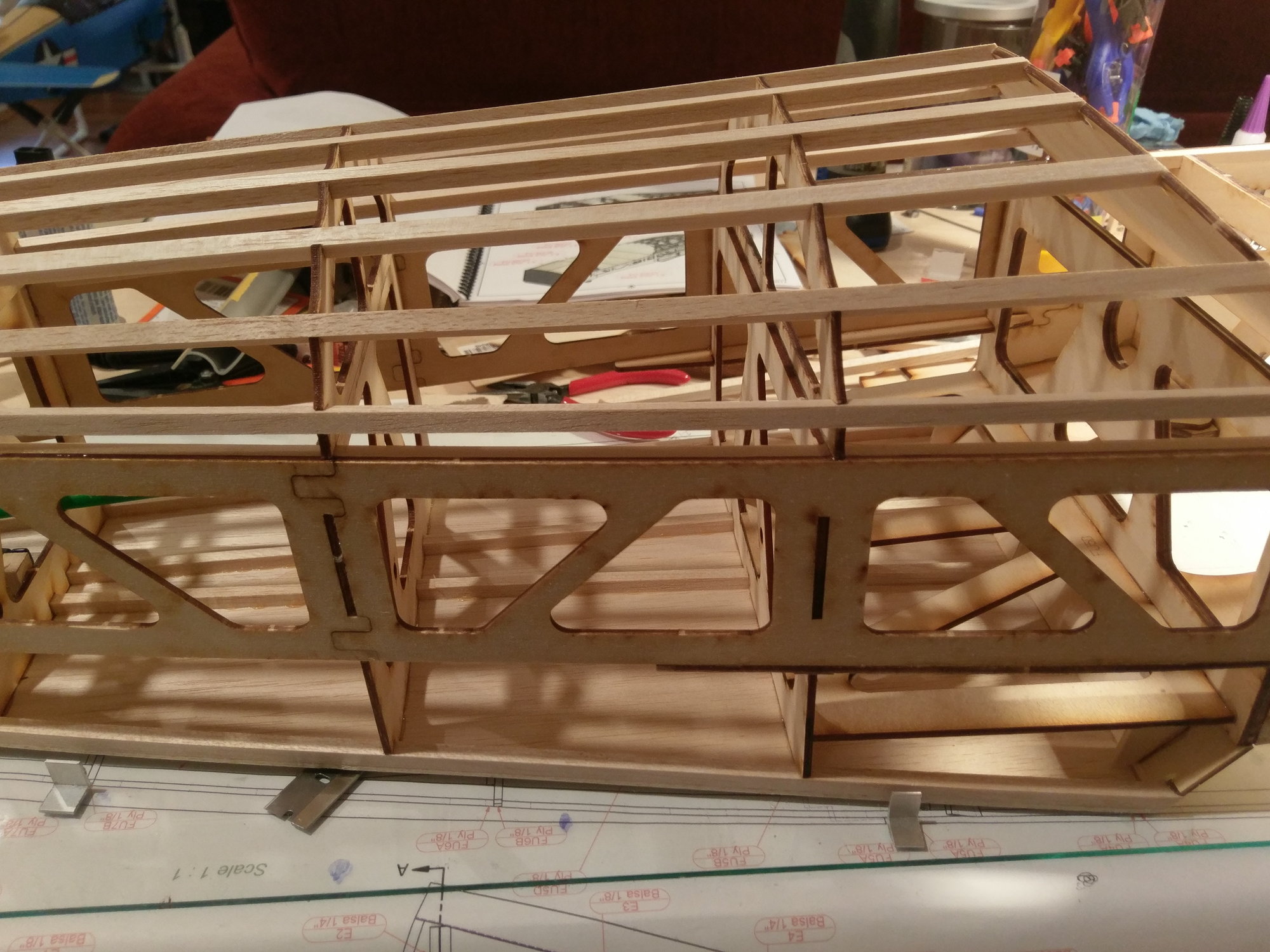
2) The laser cutting is generally excellent, and the parts interlock snugly with minimal to no gaps. Speaking of fit, that is a revelation in this kit, especially the fuselage. The interlocking tabs allow for easy framing of the wide fuselage and the final structure will no doubt be remarkably stiff.
3) The planned engine is a Valach 60. When I purchased the kit, I was going to purchase a Kolm engine, but by the time I got around to ordering it last month, the company had undergone some organizational changes and the price of the engine had been nearly doubled. So the second choice, the Valach, will be gracing the cowling.
4) The kit does not come with detailed directions like a Top Flite kit for instance. You have to follow the sequence of drawings. If you have some build experience it is fine, but you do have to think ahead now and then.
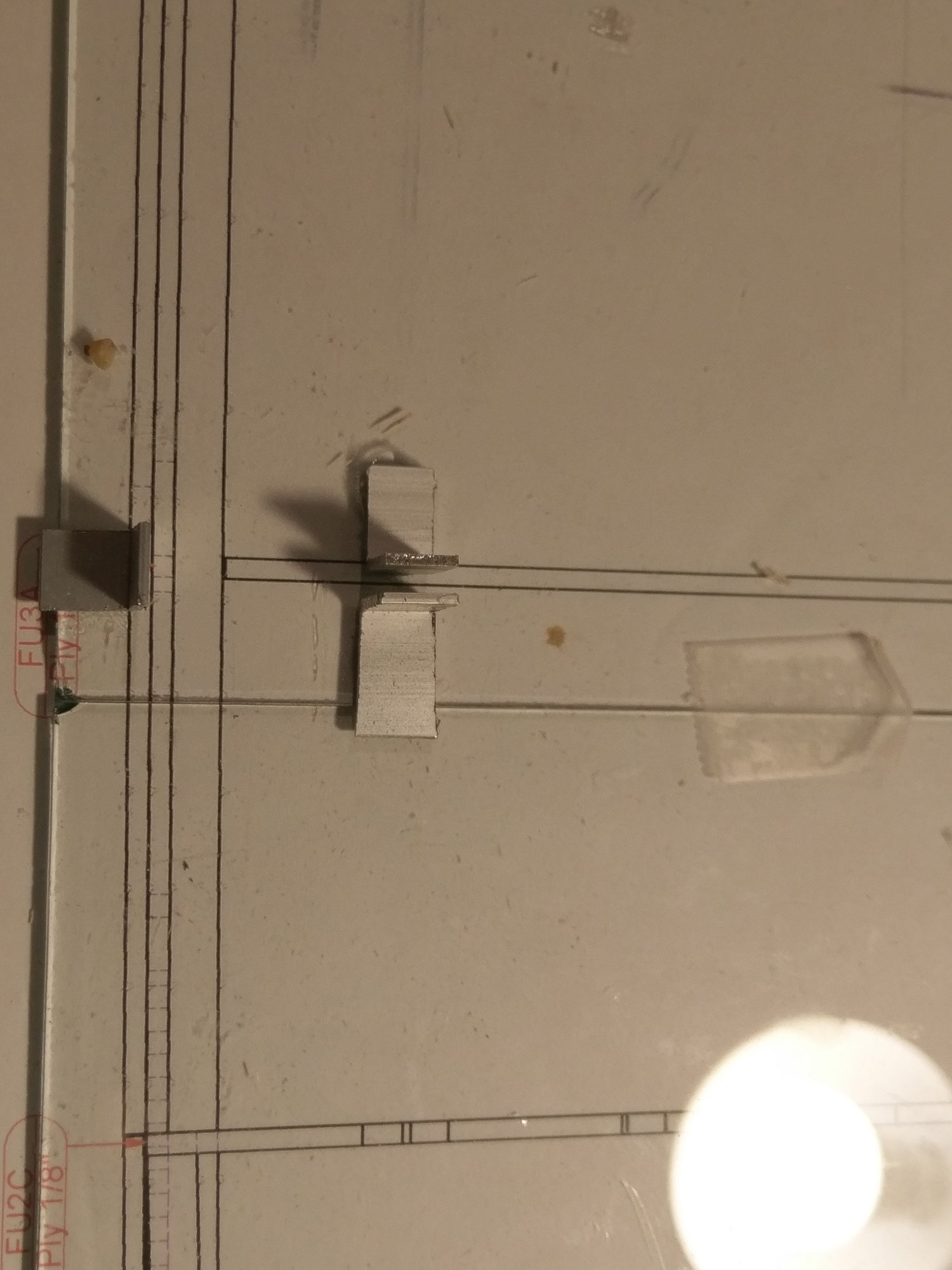
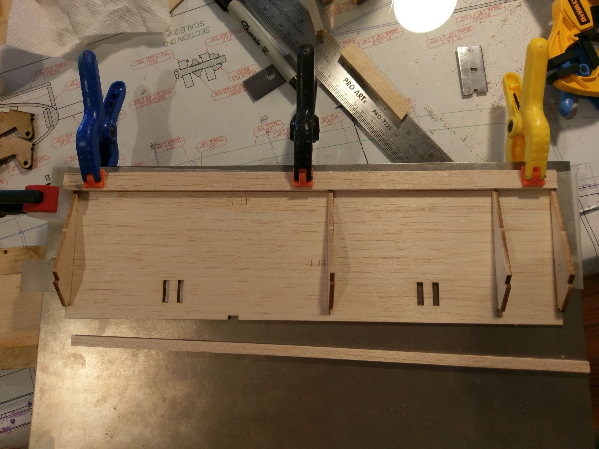
5) Build technique. I build with a glass sheet on the plans. This makes for a very flat smooth surface. For this build I used small aluminum 90 degree angles pieces to hold the formers in place. These can be easily tacked to table with CA, and then knocked off. A few wipes of a scraper blade and the glass is clean again.
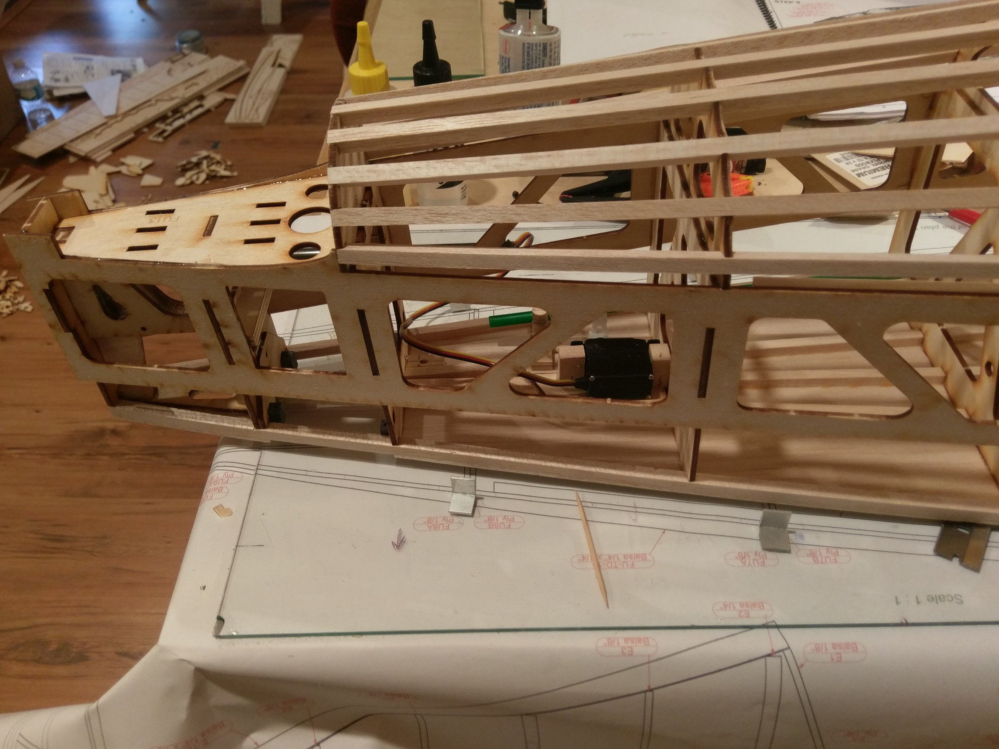
6) Design modification: Although most sport and 3D planes use the same steering arrangement as that used on the CAP, i.e. tail wheel attached to the rudder with two springs, I avoided this technique and installed a separate servo for the tail wheel.
7) Working on the ailerons now.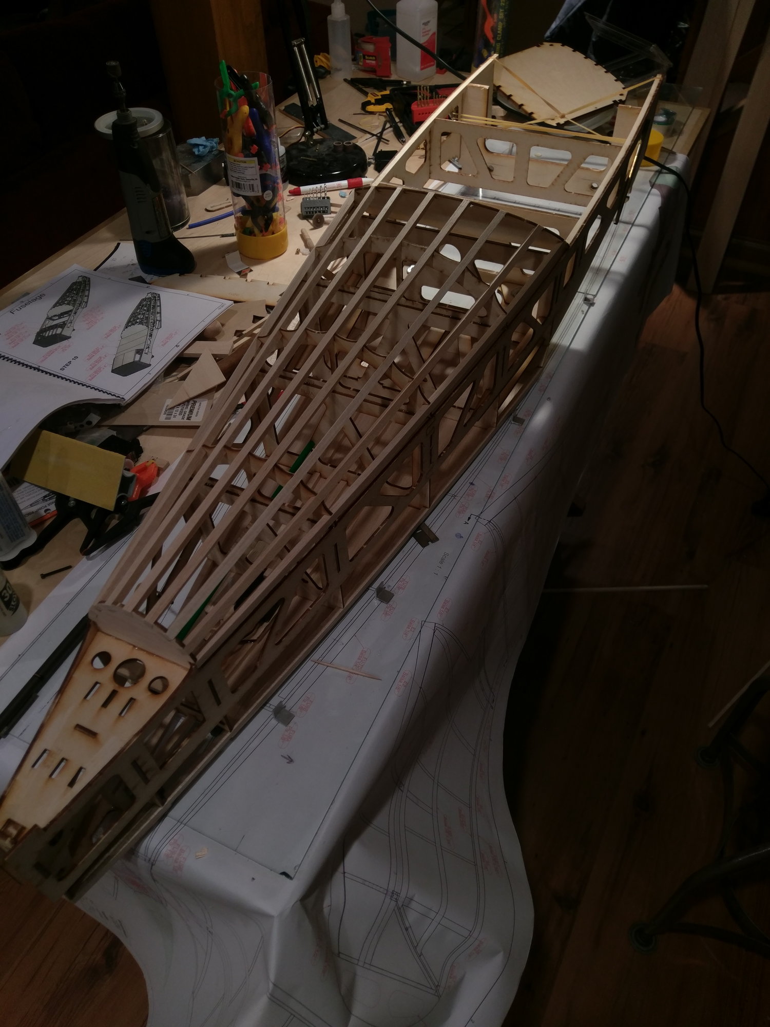
1) The quality of the wood is outstanding. The balsa is of consistent density and the plywood sheets are warp free and high density.
2) The laser cutting is generally excellent, and the parts interlock snugly with minimal to no gaps. Speaking of fit, that is a revelation in this kit, especially the fuselage. The interlocking tabs allow for easy framing of the wide fuselage and the final structure will no doubt be remarkably stiff.
3) The planned engine is a Valach 60. When I purchased the kit, I was going to purchase a Kolm engine, but by the time I got around to ordering it last month, the company had undergone some organizational changes and the price of the engine had been nearly doubled. So the second choice, the Valach, will be gracing the cowling.
4) The kit does not come with detailed directions like a Top Flite kit for instance. You have to follow the sequence of drawings. If you have some build experience it is fine, but you do have to think ahead now and then.
5) Build technique. I build with a glass sheet on the plans. This makes for a very flat smooth surface. For this build I used small aluminum 90 degree angles pieces to hold the formers in place. These can be easily tacked to table with CA, and then knocked off. A few wipes of a scraper blade and the glass is clean again.
6) Design modification: Although most sport and 3D planes use the same steering arrangement as that used on the CAP, i.e. tail wheel attached to the rudder with two springs, I avoided this technique and installed a separate servo for the tail wheel.
7) Working on the ailerons now.
01-15-2019, 06:56 AM
#48
Join Date: Feb 2013
Location: , OH
Posts: 59
Likes: 0
Received 0 Likes
on
0 Posts
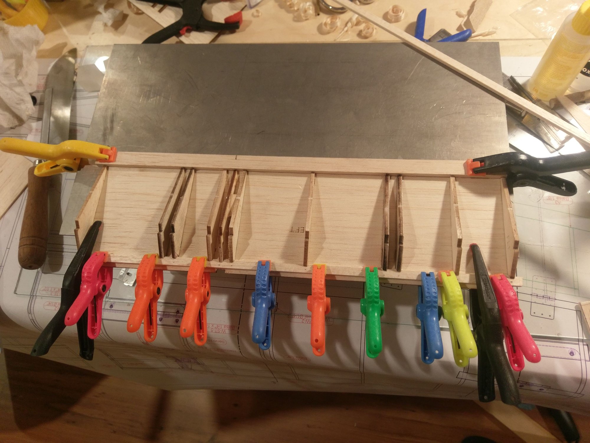
The inclement weather in the mid-west this past weekend encouraged spending time on the CAP10. The ailerons were completed and work started on the flaps, which have offset hinges. Very scale like.
 01-21-2019, 08:25 AM
#50
Join Date: Feb 2013
Location: , OH
Posts: 59
Likes: 0
Received 0 Likes
on
0 Posts
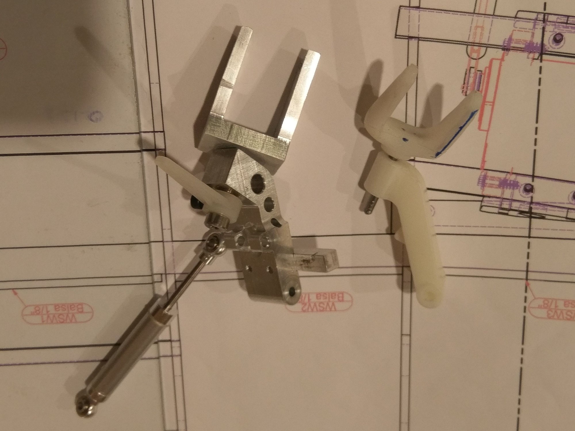
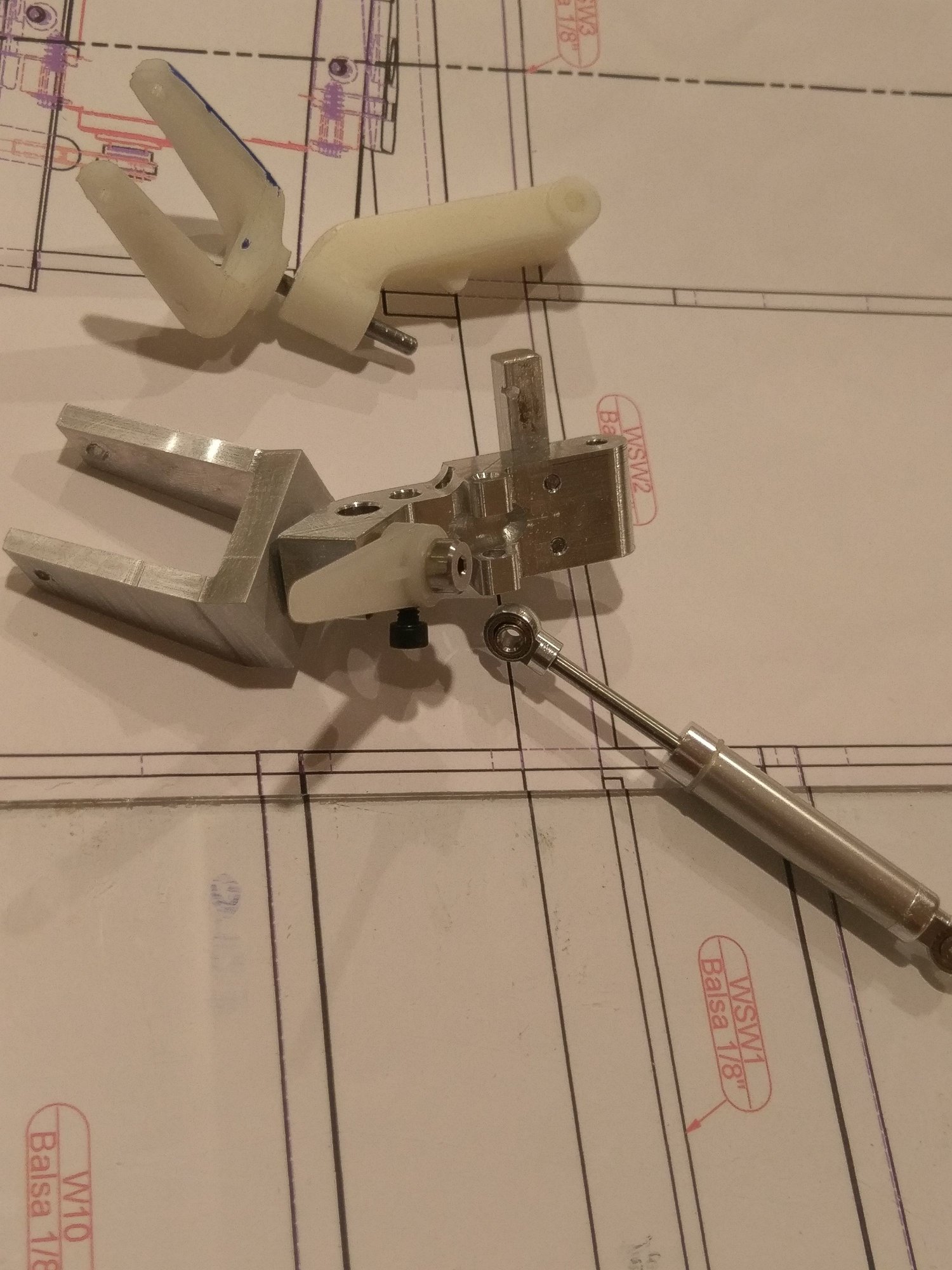
The tail wheel supplied with the kit is a sturdy nylon two part assembly. However, as I changed the design to having a separate servo for the tail wheel, I needed an arm to secure the housing. This gave rise to a new design which I proceeded to make out of aluminum. The original design used a spring encapsulated in brass tube with a piston as a shock absorber. I replaced this with an equal sized shock from a rock crawler. Replaced the inner spring with the one from the kit to keep the spring constant the same.