


Mod'd Hostetler 1/4 GeeBee R2
 02-23-2013, 06:45 PM
#76

Since I am waiting on supplies for the Horton, this weekend makes the perfect opportunity to make some progress on the GeeBee!
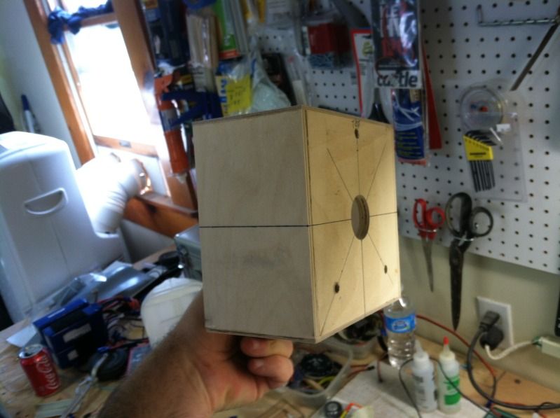
First up was building the engine mount box. Its made from 1/4" acft ply sides, 1/8" aircraft ply top/bottom and 1/2" aircraft ply firewall. this is all epoxied together and then 1/2" spruce tri-stock in the corners:
Then a hole is cut in the fuselage the same size as the outer dimension of the engine box:

Then four aluminum angles are cut and drilled for #8 bolts. The angles are then bolted to the firewall and the engine box slide into its hole. The dimension from the F1 bulkhead to the firewall is checked at all four corners of the engine box to be the same and then the angles are drilled so they are bolted to the engine box, again using #8 bolts:
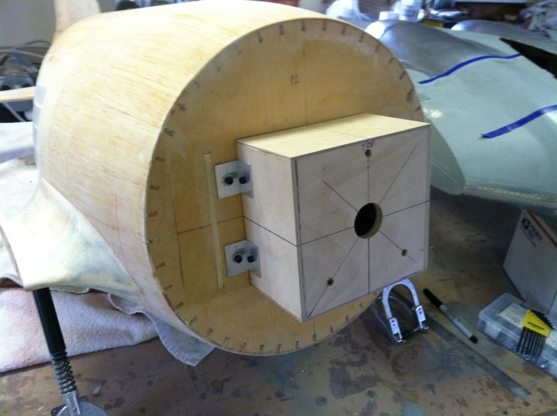
The engine box is made removable to ease maintenance and component installation in the fuselage. Not to mention the large hole in the F1 bulkhead will make installing the flying wires slightly easier, Not much, but any ease in install is worth the extra effort.
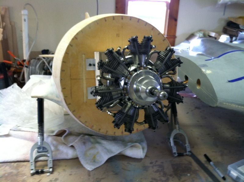
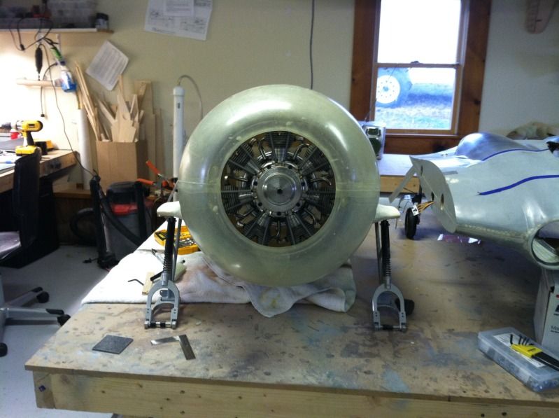
The engine (Seidel ST-7-70) was then installed onto the engine box.
Then the foam form I used to ensure the cowling was round when i installed the carbon ring to the cowl was modified to fit over the engine.. basically I cut a big hole in the middle of it. haha

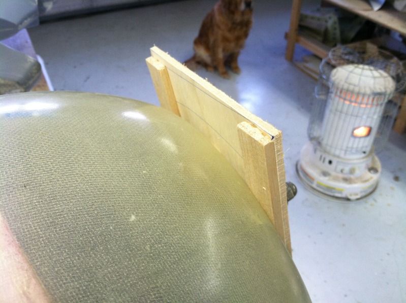
Then a fancy shmancy cowling alignment device was built... This high-tech item is devised of the latest cowling alignment technology and made of some pretty difficult materials...
Basically, a piece of lite-ply was cut to 6" width. Then a 10mm hole (crankshaft diameter) was drilled in the center of it. Then some 1/4" thick balsa was laminated to the face of it. Some Balsa blocks were also glued perpendicular to the face as well so the cowl lip rested on these blocks, and then this entire apparatus was bolted onto the engine after the cowling was put into position. I forgot to get a picture of this amazing technology, but i'll get some tomorrow.
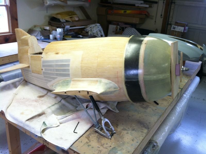
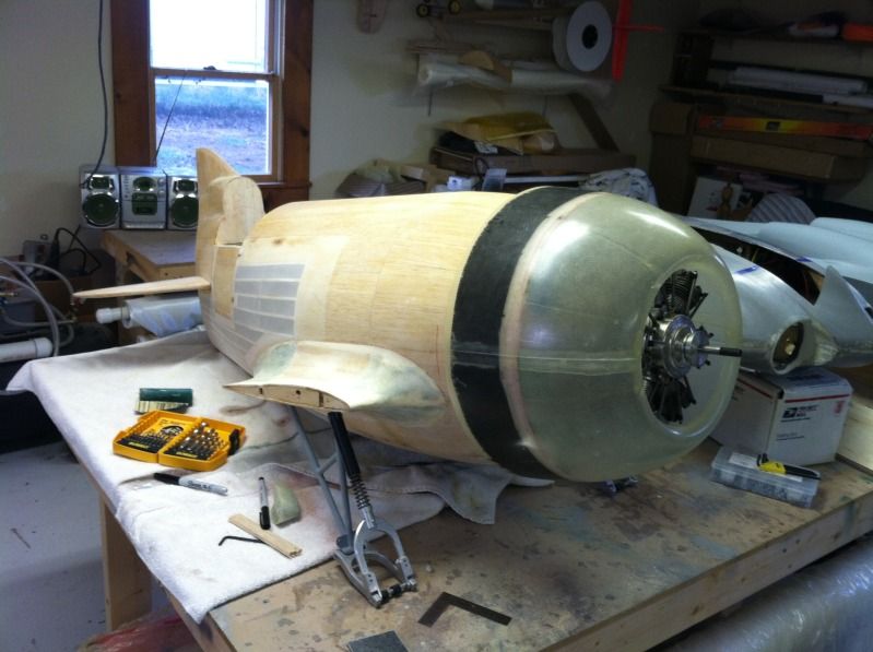
Here's a photo of the cowling and the alignment tech in place.
Then using some left-over material from the Horton, i made up the cowling mount tabs.. In order to keep the cowling mounting hidden and still be easily removed, takes some head scratching. You can't get to the bolts from the front of the airplane due to the cowling shape. Externally seen attachment bolts is not an option (for me) and holes in the cowling to get to the bolts from the front aren't an option either..
Soooo, that only leaves getting to them from the back side. Again, I forgot pictures, so i'll get those tomorrow..
The cowling mount tabs on the fuselage are made from the following layup:
2oz glass, 5oz CF, 3mm Rohacell 71, 5oz CF, 2oz Glass (this comes out to be about .15" thick)
These tabs are 1 1/2" x 4" roughly. They are screwed and epoxied to the ply F1 bulkhead so they are at the 1:30, 4:30, 7:30 and 10:30 positions.
Then four pieces of some 5/32" OD brass tubing is cut to .2" in length. Then the cowling bolt holes in the tabs are drilled out to 9/64". The brass tube is then pressed into the 9/64" hole and these are epoxied into place.
The cowling is then put back into position and then a measurement from the aft face of the firewall mounted cowling tabs to the aft edge of the cowl are taken for all four tabs and add .15" to these measurements.
THEN (yea all this crap for just mounting a flipping cowl... why didn't i just put some hardwood blocks and wood screws in place to hold this dang thing on?)
Then using more of that layup stuff, some more tabs are made up and epoxied to the cowling using the measurements taken above.
Then the cowl goes back on, and the brass tube hole position is transferred to these tabs that are epoxied to the cowl.
Blind nuts are then installed into these tabs and epoxied as well. The reason for the brass tubes in the fuse mounted tabs is since the core material is foam, they provide a hard point so as not to allow the bolts and tab holes to enlarge due to vibration. The blind nuts in the cowl tabs keep that from happening for those tabs.
When all this has been said and done, the cowling mount bolts are obtained from the gap between the cowling and the fuselage. The mounting is completely concealed and very stiff.
Engine and cowling mounting photo's:
First up was building the engine mount box. Its made from 1/4" acft ply sides, 1/8" aircraft ply top/bottom and 1/2" aircraft ply firewall. this is all epoxied together and then 1/2" spruce tri-stock in the corners:
Then a hole is cut in the fuselage the same size as the outer dimension of the engine box:
Then four aluminum angles are cut and drilled for #8 bolts. The angles are then bolted to the firewall and the engine box slide into its hole. The dimension from the F1 bulkhead to the firewall is checked at all four corners of the engine box to be the same and then the angles are drilled so they are bolted to the engine box, again using #8 bolts:
The engine box is made removable to ease maintenance and component installation in the fuselage. Not to mention the large hole in the F1 bulkhead will make installing the flying wires slightly easier, Not much, but any ease in install is worth the extra effort.
The engine (Seidel ST-7-70) was then installed onto the engine box.
Then the foam form I used to ensure the cowling was round when i installed the carbon ring to the cowl was modified to fit over the engine.. basically I cut a big hole in the middle of it. haha
Then a fancy shmancy cowling alignment device was built... This high-tech item is devised of the latest cowling alignment technology and made of some pretty difficult materials...
Basically, a piece of lite-ply was cut to 6" width. Then a 10mm hole (crankshaft diameter) was drilled in the center of it. Then some 1/4" thick balsa was laminated to the face of it. Some Balsa blocks were also glued perpendicular to the face as well so the cowl lip rested on these blocks, and then this entire apparatus was bolted onto the engine after the cowling was put into position. I forgot to get a picture of this amazing technology, but i'll get some tomorrow.
Here's a photo of the cowling and the alignment tech in place.
Then using some left-over material from the Horton, i made up the cowling mount tabs.. In order to keep the cowling mounting hidden and still be easily removed, takes some head scratching. You can't get to the bolts from the front of the airplane due to the cowling shape. Externally seen attachment bolts is not an option (for me) and holes in the cowling to get to the bolts from the front aren't an option either..
Soooo, that only leaves getting to them from the back side. Again, I forgot pictures, so i'll get those tomorrow..
The cowling mount tabs on the fuselage are made from the following layup:
2oz glass, 5oz CF, 3mm Rohacell 71, 5oz CF, 2oz Glass (this comes out to be about .15" thick)
These tabs are 1 1/2" x 4" roughly. They are screwed and epoxied to the ply F1 bulkhead so they are at the 1:30, 4:30, 7:30 and 10:30 positions.
Then four pieces of some 5/32" OD brass tubing is cut to .2" in length. Then the cowling bolt holes in the tabs are drilled out to 9/64". The brass tube is then pressed into the 9/64" hole and these are epoxied into place.
The cowling is then put back into position and then a measurement from the aft face of the firewall mounted cowling tabs to the aft edge of the cowl are taken for all four tabs and add .15" to these measurements.
THEN (yea all this crap for just mounting a flipping cowl... why didn't i just put some hardwood blocks and wood screws in place to hold this dang thing on?)
Then using more of that layup stuff, some more tabs are made up and epoxied to the cowling using the measurements taken above.
Then the cowl goes back on, and the brass tube hole position is transferred to these tabs that are epoxied to the cowl.
Blind nuts are then installed into these tabs and epoxied as well. The reason for the brass tubes in the fuse mounted tabs is since the core material is foam, they provide a hard point so as not to allow the bolts and tab holes to enlarge due to vibration. The blind nuts in the cowl tabs keep that from happening for those tabs.
When all this has been said and done, the cowling mount bolts are obtained from the gap between the cowling and the fuselage. The mounting is completely concealed and very stiff.
Engine and cowling mounting photo's:
 02-24-2013, 06:48 PM
#78
ORIGINAL: frequent flyer
Outstanding!......Really enjoy this build. I'm building the same only wish I had an engine like that.
Outstanding!......Really enjoy this build. I'm building the same only wish I had an engine like that.
02-24-2013, 06:56 PM
#79
Didn't do much work to the GeeBee today. My horton 229 project is burning me out to where i really just sit and stare at whatever it is in front of me at the time wondering why i even bother sometimes. lol
Anyways, I did do some things productive..
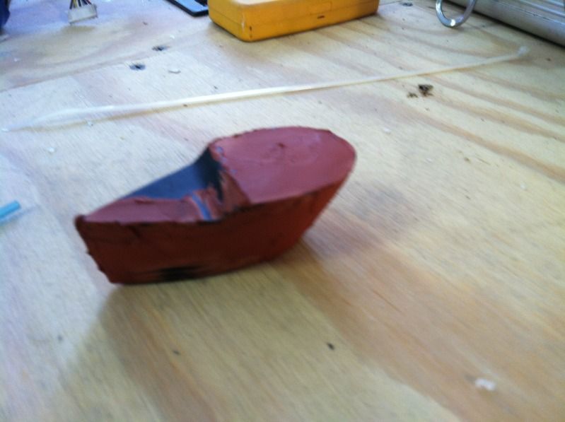
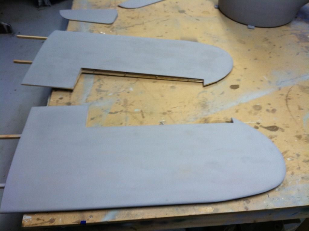
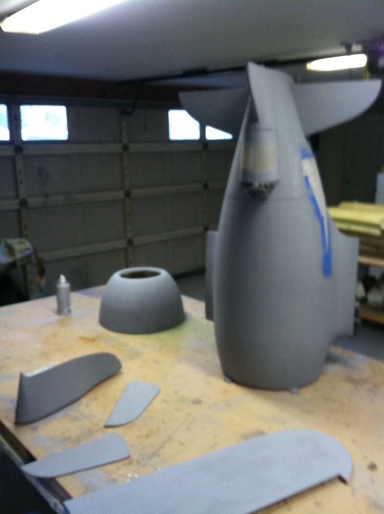
I sprayed some primer on the tail wheel fairing plug and applied some glazing putty as well.. then begins the entire sand, fill, primer, sand, fill, prime, etc etc etc saga until is smooth. Then i've got to mold this sucker
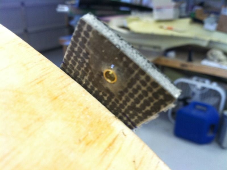
Here is the F1 bulkhead cowl mounting tabs:

Then brass tube inserts in the F1 bulkhead cowl mounting tabs:
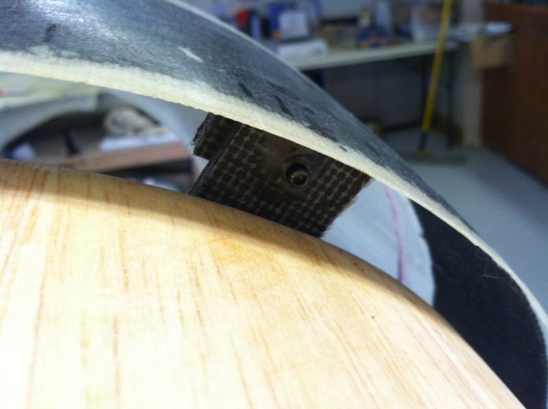
The mounting tabs for the cowling in the cowling (these hold the blind-nuts)
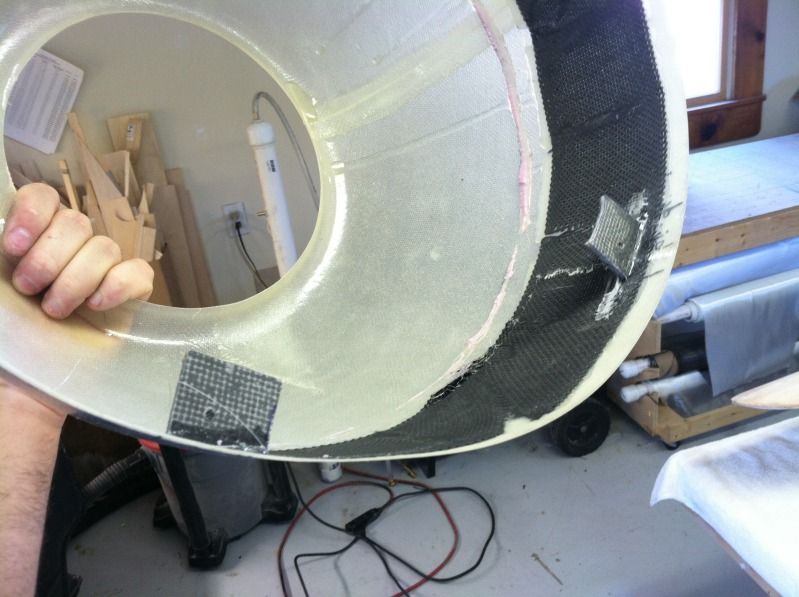
And a shot from behind the cowling looking forward showing how the cowl is bolted into position:
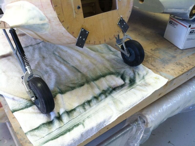
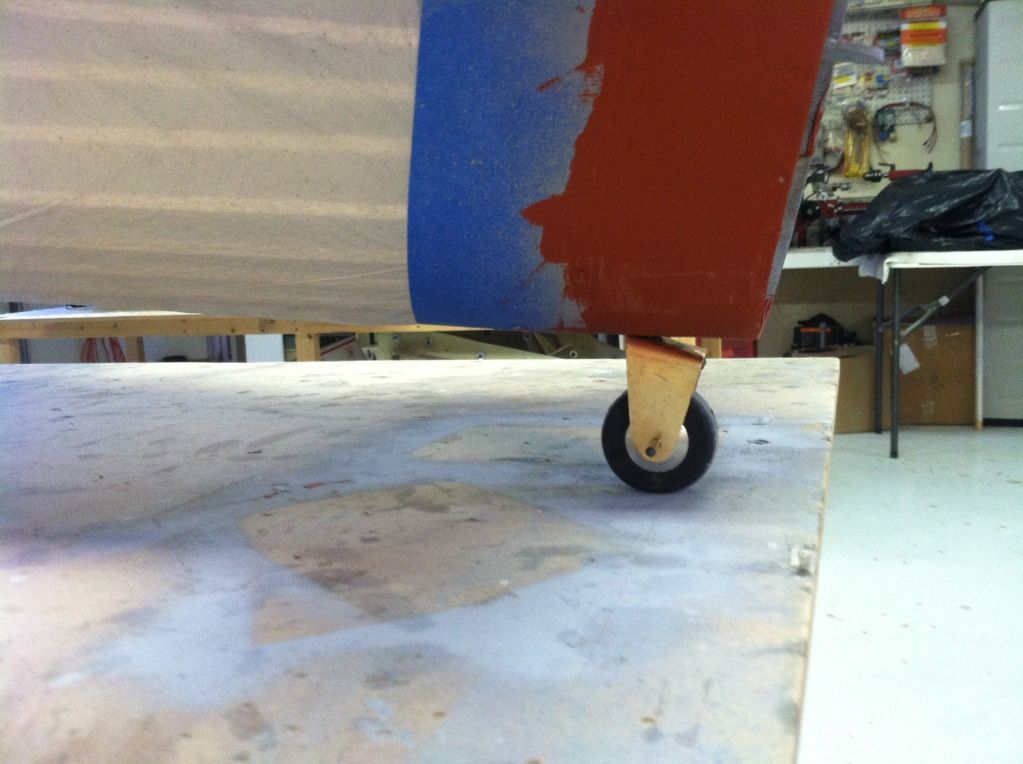
I also trimmed the axle spacers to the correct length for the tires to fit and installed them.. Now i've got to figure out how to do the wheel pants and pant fairings. I'm not looking forward to this as the bottom has to move with the shock absorption of the landing gear without binding AND they have to be slotted for the flying wires to move as well. And to make it even more fun, they are in 3 separate pieces and the bottom has to be removable.. What have i gotten myself into!?
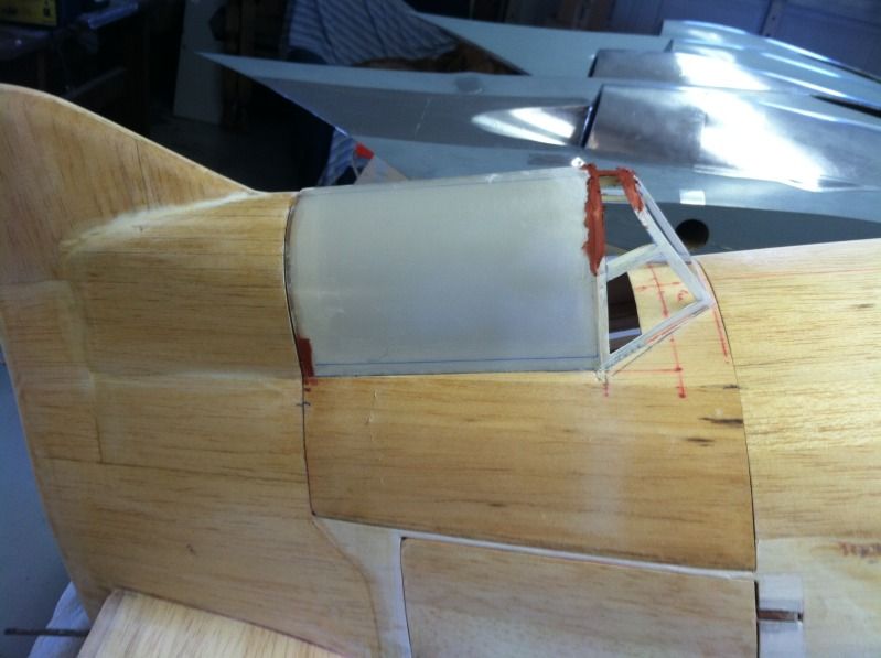
The canopy frame was also finished up, almost. .015" G-10 was put into place between the canopy frame and the headrest bulkhead. I've got to trim it to give it a 1/4" frame,but otherwise its done and ready for paint.
Anyways, I did do some things productive..
I sprayed some primer on the tail wheel fairing plug and applied some glazing putty as well.. then begins the entire sand, fill, primer, sand, fill, prime, etc etc etc saga until is smooth. Then i've got to mold this sucker
Here is the F1 bulkhead cowl mounting tabs:
Then brass tube inserts in the F1 bulkhead cowl mounting tabs:
The mounting tabs for the cowling in the cowling (these hold the blind-nuts)
And a shot from behind the cowling looking forward showing how the cowl is bolted into position:
I also trimmed the axle spacers to the correct length for the tires to fit and installed them.. Now i've got to figure out how to do the wheel pants and pant fairings. I'm not looking forward to this as the bottom has to move with the shock absorption of the landing gear without binding AND they have to be slotted for the flying wires to move as well. And to make it even more fun, they are in 3 separate pieces and the bottom has to be removable.. What have i gotten myself into!?
The canopy frame was also finished up, almost. .015" G-10 was put into place between the canopy frame and the headrest bulkhead. I've got to trim it to give it a 1/4" frame,but otherwise its done and ready for paint.
02-24-2013, 07:22 PM
#82

My Feedback: (6)

Join Date: Feb 2003
Location: Grand Junction, Colorado
Posts: 1,484
Likes: 0
Received 4 Likes
on
4 Posts
I checked out G&L Hobbies site but did not see where they sell Glass Parts separate.? Do I need to call or something?
What size wheels did you use?
02-24-2013, 07:24 PM
#83
He had an add in the classifieds section here for the cowling canopy and wheel pants for around $100, i didn't need the canopy so i got it a bit cheaper. i'd just send him an email telling him what you need.
I think the tires are 5" in diameter, not 100% sure though
I think the tires are 5" in diameter, not 100% sure though
02-24-2013, 07:33 PM
#86
You are a great builder and I really appreciate all the photos that you have been putting into this thread.....Thanks a million......Sebo
04-28-2013, 06:00 PM
#87
Well,
Im going to be bouncing back and forth between a few projects for the next few weeks, maybe months. Ive got to help Tom get his Horten flying, the deadline for that is in 2 1/2 weeks. I need materials for the F14 project, and no cash to buy them. Sooo. GeeBee time it is!
While tom was taping the panel lines on his last horten wing, i did some work to the geebee's wings.
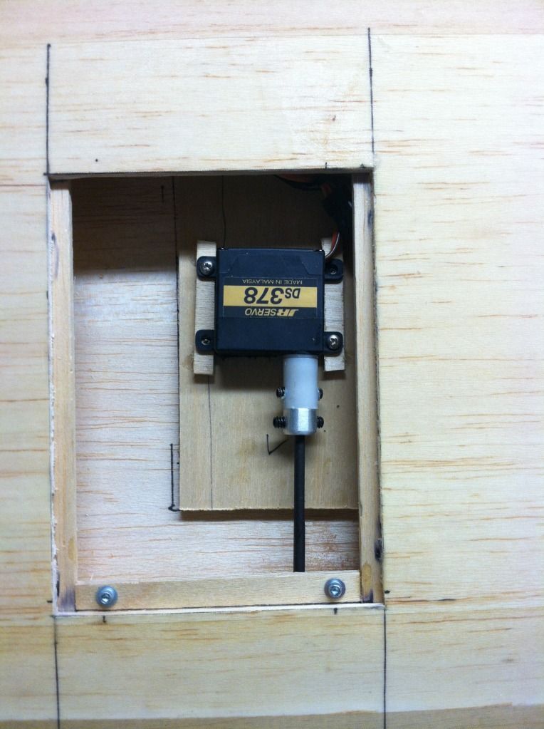
I made up a 1/8" ply plate mout for the aileron servo. Shortened the 32* rds rod 1", epoxied Nigels hinges in place permanently (i really love those hinges), the cut the slot for the RDS pocket and tacked the pocket in place. Then epoxied the servo mount plate in place and test ran the rds system.
This is the first time i have ever used the RDS system, and i am really impressed. I love the sleek look of no external linkages, i can using this system more often in the future.
Heres a few pictures:

So here is the list of stuff left to do before the geebee can get painted:
Rds pockets permanently installed
Right wing aileron servo and linkage setup
Flying wire openings cut in both wing panels
Flying wire openings cut in the fuselage
Upper wheel pant fairings cut and installed
Lower wheel pants cut in half, mounted, flying wire slots cut and the front half made removable.
Lower flyig wire fuselage mount made
Tail wheel fairing finish sanded
Tail wheel fairing molded
Tail wheel fairing part laid up
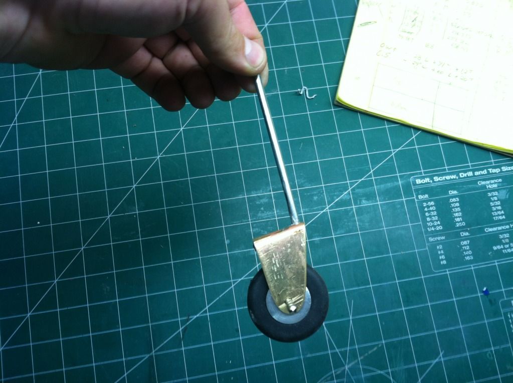
Tailwheel fork made
Fuselage primed and pinholes filled
Canopy hatch retention system
Canopy hatch interior finishing
Fuel tank and throttle servo mounts
Receiver and battery mount
On/off switch mount
Extensions made
Preliminary weight and balance
Rudder servo linkage made
So as you can see, lots to do before i can even think about painting!
Im going to be bouncing back and forth between a few projects for the next few weeks, maybe months. Ive got to help Tom get his Horten flying, the deadline for that is in 2 1/2 weeks. I need materials for the F14 project, and no cash to buy them. Sooo. GeeBee time it is!
While tom was taping the panel lines on his last horten wing, i did some work to the geebee's wings.
I made up a 1/8" ply plate mout for the aileron servo. Shortened the 32* rds rod 1", epoxied Nigels hinges in place permanently (i really love those hinges), the cut the slot for the RDS pocket and tacked the pocket in place. Then epoxied the servo mount plate in place and test ran the rds system.
This is the first time i have ever used the RDS system, and i am really impressed. I love the sleek look of no external linkages, i can using this system more often in the future.
Heres a few pictures:
So here is the list of stuff left to do before the geebee can get painted:
Rds pockets permanently installed
Right wing aileron servo and linkage setup
Flying wire openings cut in both wing panels
Flying wire openings cut in the fuselage
Upper wheel pant fairings cut and installed
Lower wheel pants cut in half, mounted, flying wire slots cut and the front half made removable.
Lower flyig wire fuselage mount made
Tail wheel fairing finish sanded
Tail wheel fairing molded
Tail wheel fairing part laid up
Tailwheel fork made
Fuselage primed and pinholes filled
Canopy hatch retention system
Canopy hatch interior finishing
Fuel tank and throttle servo mounts
Receiver and battery mount
On/off switch mount
Extensions made
Preliminary weight and balance
Rudder servo linkage made
So as you can see, lots to do before i can even think about painting!
04-28-2013, 06:36 PM
#89
They are available from IFR machine works.
Basically its a plastic coupler that goes on the servo, then a machine piece that connects a 1/8" piece or music wire with a short bend at one end (32* in this case), that then bolts into the metal/plastic coupler.
There is then a "box" that is glued into the control surface that the bend in the music wire rides in (its a tight, but smooh fit). The bend dictates the amount of deflection basically.
Ill get more photos when i go to install the system in the other wing. The servos are nice as they are only about 1/4-3/8" thick.

 05-11-2013, 03:35 PM
#92
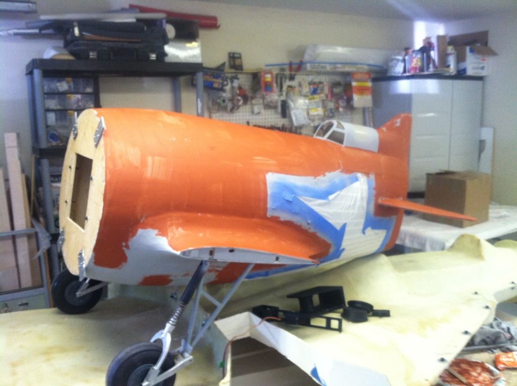
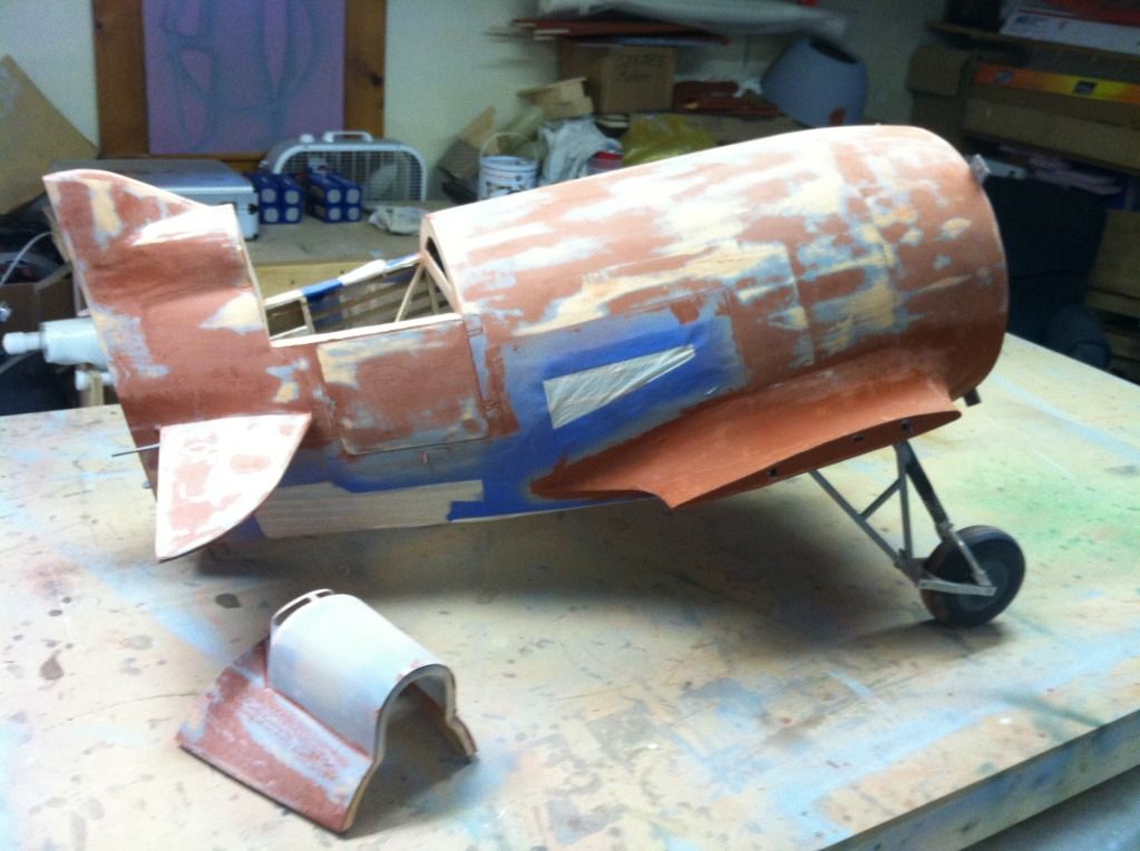
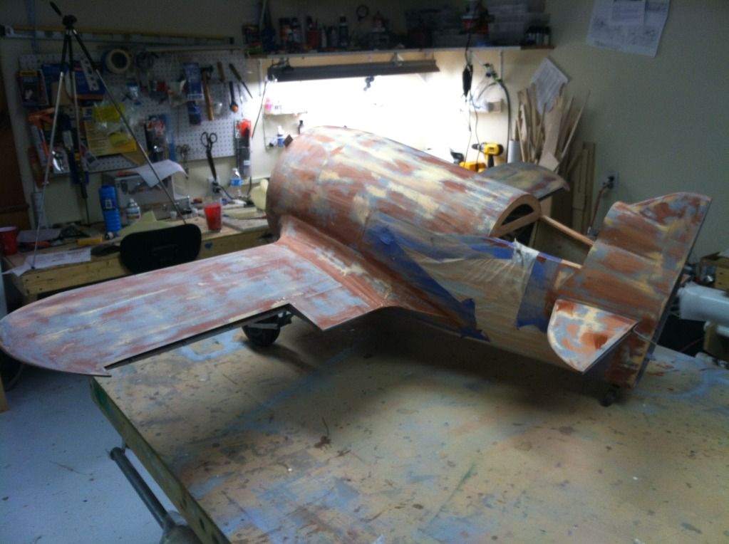
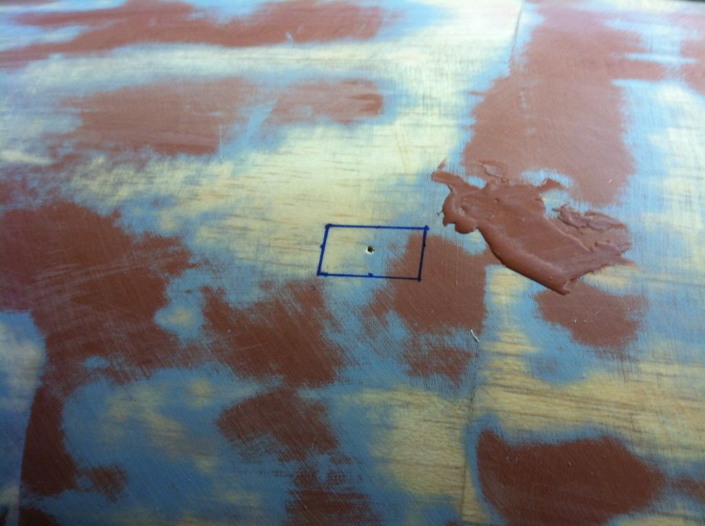
Slowly working tasks away. I applied the Red 3M glazing spot putty to 1/2 of the airframe today.
I only use one coat of resin when glassing my models now, and the smear a slightly heavier coat than average over the entire airframe. 99% of this gets sanded off, only leaving what is inside low spots and pinholes:
I only use one coat of resin when glassing my models now, and the smear a slightly heavier coat than average over the entire airframe. 99% of this gets sanded off, only leaving what is inside low spots and pinholes:
 05-27-2013, 06:51 PM
#95
Since today was a day off (one of the few I get through the year).. it was GeeBee Time!
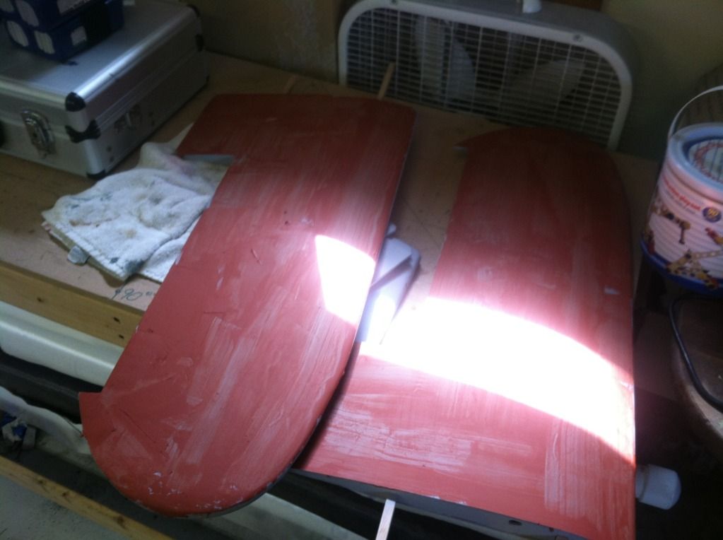
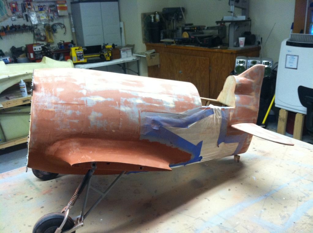
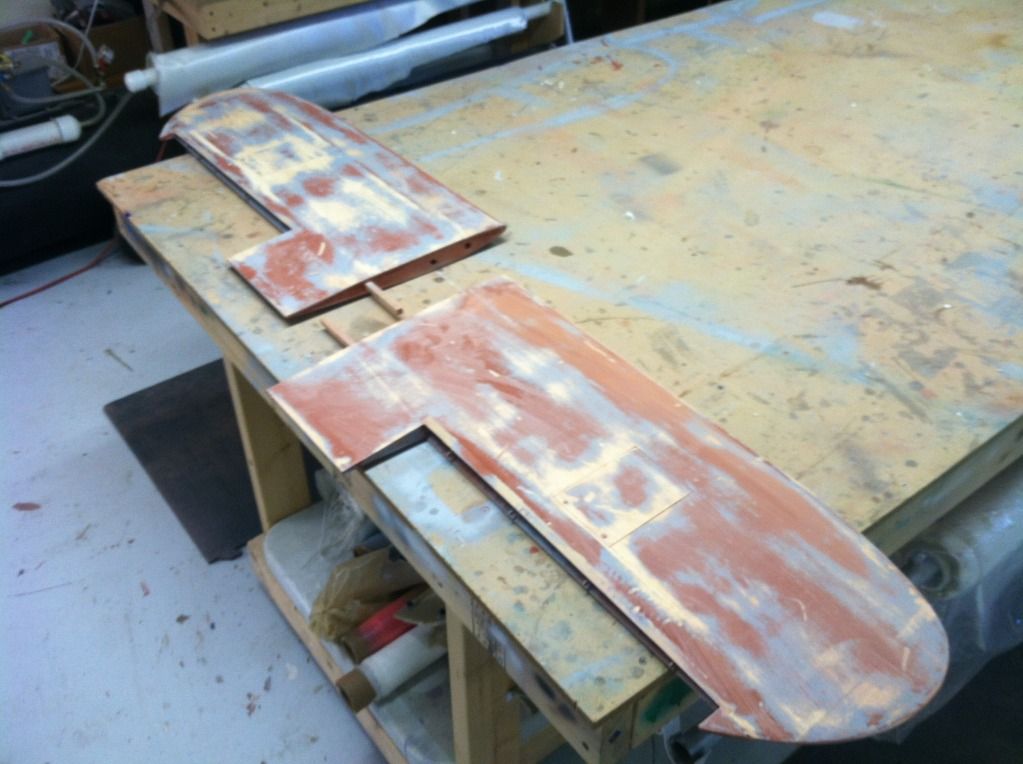
first up was a whole bunch of sanding.. But the entire airframe has had all of its red glazing filler sanded off. Round 1, done!
Then I started to trim and fit up the landing gear fairings and wheel pants
And then quickly decided to forget that.. too much "how the heck do I attach that" and not enough answer's for it.. soo i'll do it later, sometime... anyone want to come do it for me?
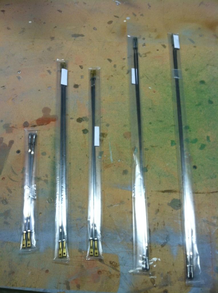
So since i'm procrastinating on the wheel pants (again), i figured i'd make use of the pretty flying wires...
First up, a photo of the flying wires, all Ten of them..
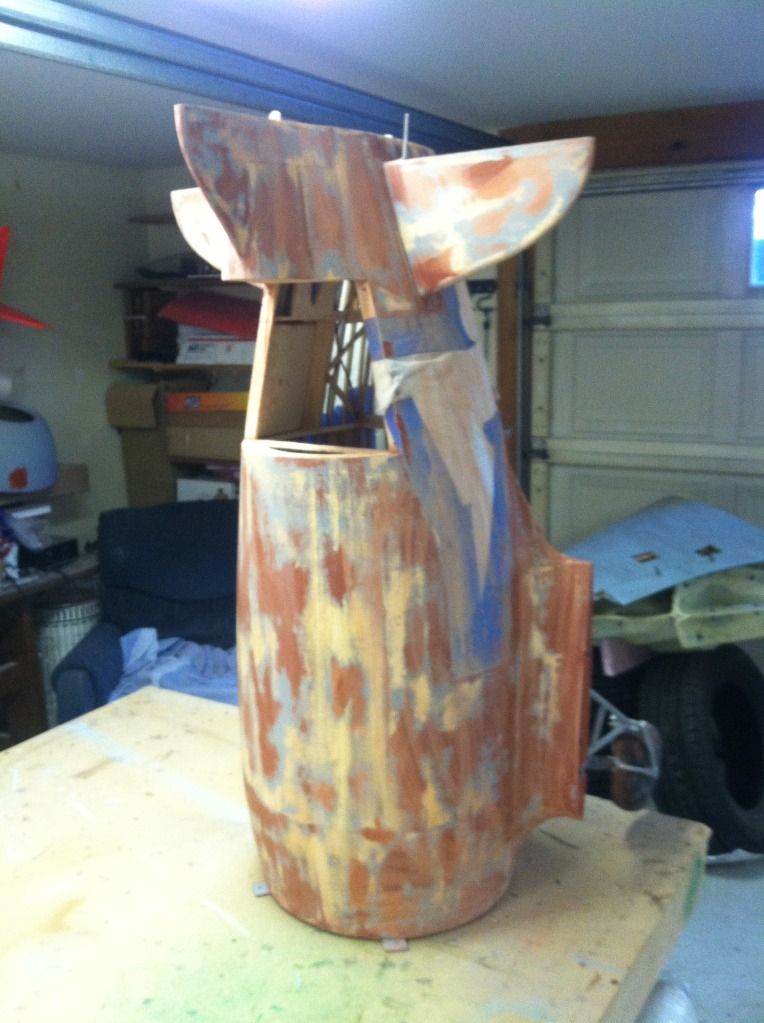
The wing panels where then installed to the fuse
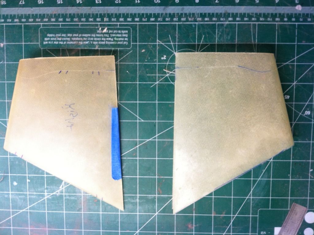
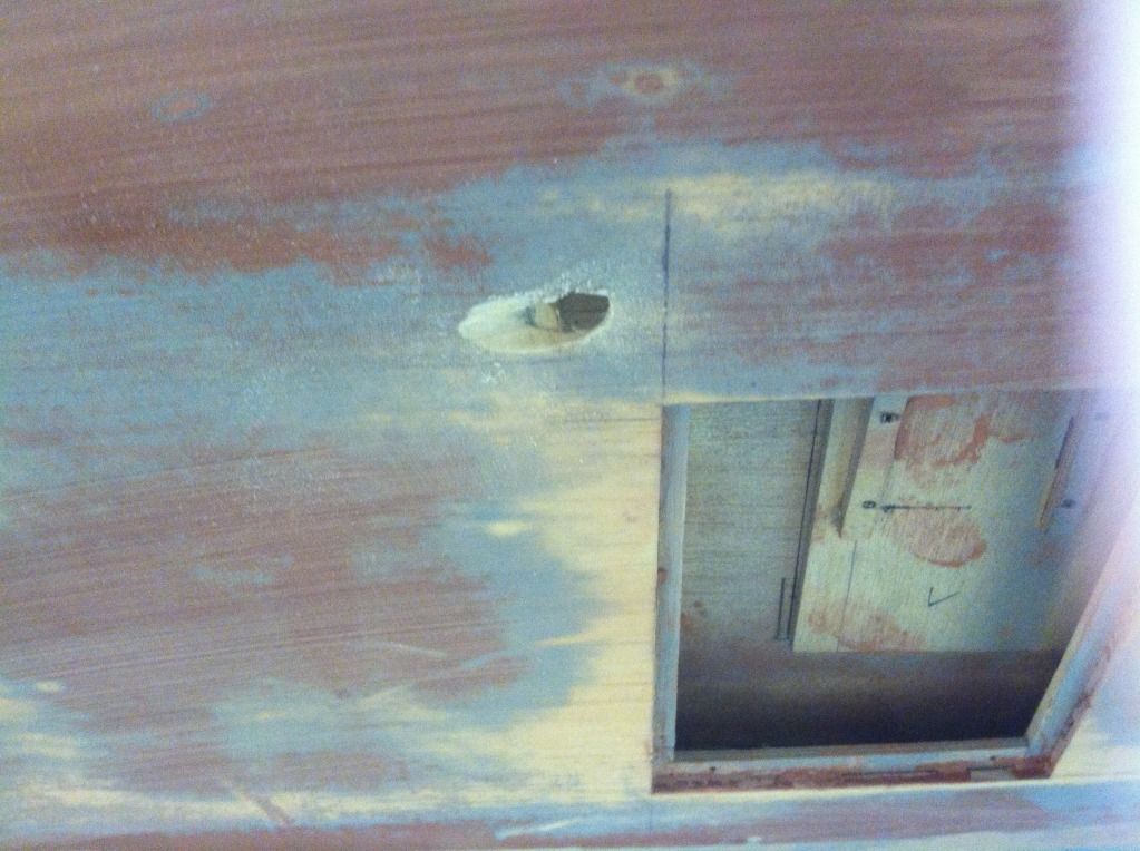
Holes in the wings and fuselage marked for the wires to go through:
And then i realized the schmuck who marked the wire positions must of been drunk as they weren't even close on the fuse... Ohh well, I have an idea on how to fix that, and it involves some G-10 inset into the surface and some body filler... That is why I only did round one of body work!
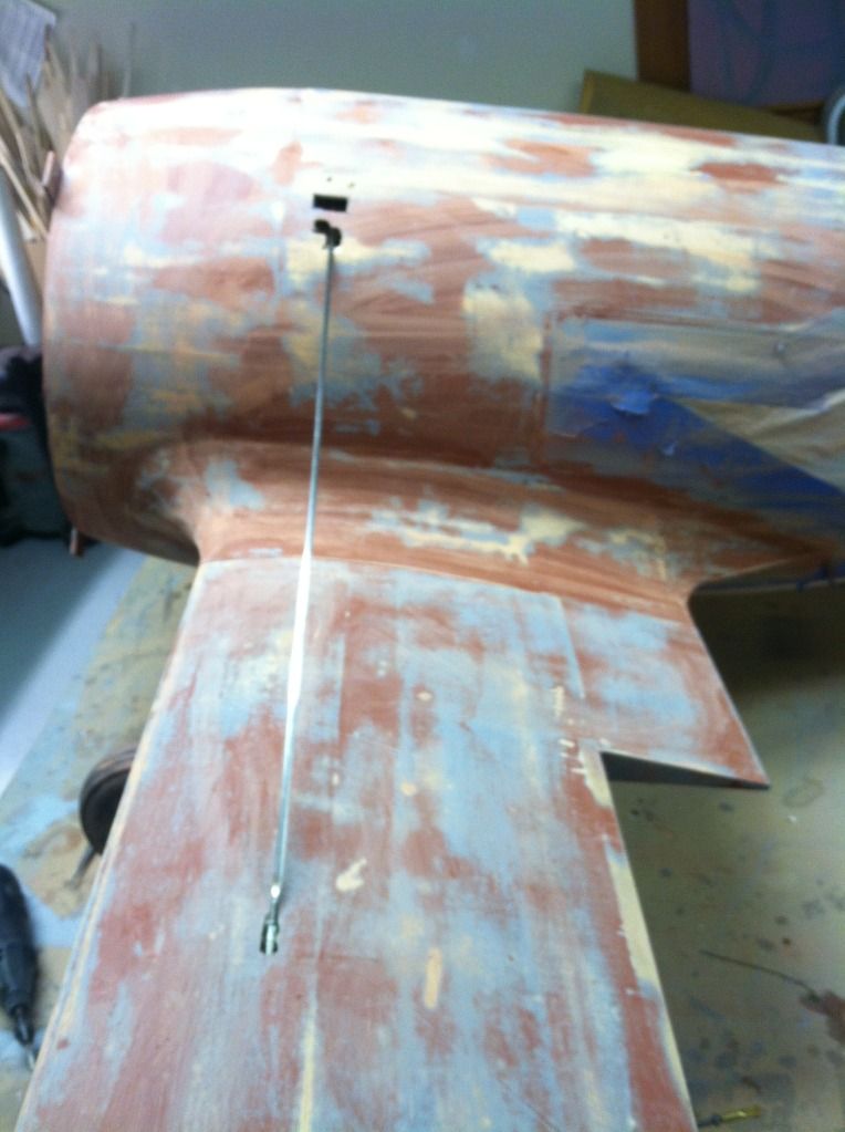
So here's a shot of the first flying wire on the left wing
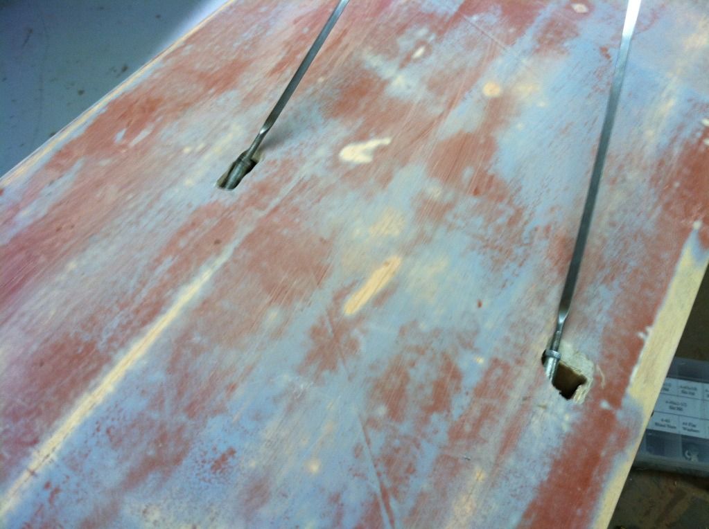
And a pair of photo's of the flying wire entry points into the wing panel.. Top, then bottom:
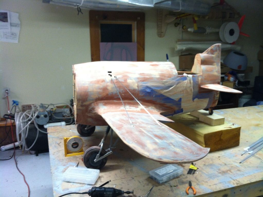
And the final photo for the evening is of the left wing with all of its wires installed. I'll do the right side or the center LG wires tomorrow.. Unfortunately, one of the flying wire attachment ends broke, so I will have to order another one of those..
first up was a whole bunch of sanding.. But the entire airframe has had all of its red glazing filler sanded off. Round 1, done!
Then I started to trim and fit up the landing gear fairings and wheel pants
And then quickly decided to forget that.. too much "how the heck do I attach that" and not enough answer's for it.. soo i'll do it later, sometime... anyone want to come do it for me?
So since i'm procrastinating on the wheel pants (again), i figured i'd make use of the pretty flying wires...
First up, a photo of the flying wires, all Ten of them..
The wing panels where then installed to the fuse
Holes in the wings and fuselage marked for the wires to go through:
And then i realized the schmuck who marked the wire positions must of been drunk as they weren't even close on the fuse... Ohh well, I have an idea on how to fix that, and it involves some G-10 inset into the surface and some body filler... That is why I only did round one of body work!
So here's a shot of the first flying wire on the left wing
And a pair of photo's of the flying wire entry points into the wing panel.. Top, then bottom:
And the final photo for the evening is of the left wing with all of its wires installed. I'll do the right side or the center LG wires tomorrow.. Unfortunately, one of the flying wire attachment ends broke, so I will have to order another one of those..
05-27-2013, 07:58 PM
#98
Member
Join Date: Aug 2012
Location: EdentonNC
Posts: 35
Likes: 0
Received 0 Likes
on
0 Posts
Thomas,Great build! I've ben following since the start. I do wish you had more days off.Where did you get the flying wires please?ThanksJules