


Top Flight Giant scale P-47 build by Glenn Williams
 07-13-2014, 04:54 AM
#176

Thread Starter
Join Date: Sep 2007
Location: Haltom,
TX
Posts: 1,181
Likes: 0
Received 0 Likes
on
0 Posts
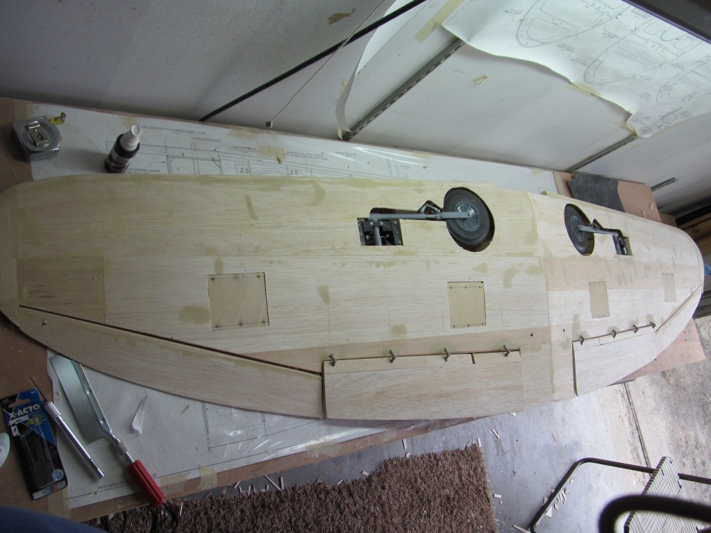
Hey guys: This will probably be the last post for about a week or two. I glued the forward lower wing skins on. I forgot to mention that the main landing gear struts scissor links were installed to the rear as shipped from Robart. I did not realize this and make up the wheel wells as the gear was shipped that way.
When I copied the plans to make a template, I discovered that the mains needed to be swapped so the scissor links were facing the front as per the plans. Thank goodness there was no major modification needed except for the forward skin I had already cut.
Anyway, I have now glued the aft lower skin to the wing and the right wing is glued and drying.
More later in a week or two if all goes as planned.
Glenn
 07-18-2014, 05:02 PM
#177
Thread Starter
Join Date: Sep 2007
Location: Haltom,
TX
Posts: 1,181
Likes: 0
Received 0 Likes
on
0 Posts
Got back into town This evening. Got to work a little while. I will be leaving again Sunday for 4 days or so. Anyway Got both bottom flaps and aileron skins installed and the inboard flap skins installed. I am currently sanding the leading edges to match the wing skins. I hope I will be able to post some progress tomorrow. We will see.
Glenn


Glenn
07-19-2014, 01:32 PM
#178
Thread Starter
Join Date: Sep 2007
Location: Haltom,
TX
Posts: 1,181
Likes: 0
Received 0 Likes
on
0 Posts
This morning was spent cutting out the ailerons and flaps, then profiling the flap ribs on the trailing edge of the wing into gussets. After that the aileron leading edges were tack glued to the trailing edge of the wing, match sanded then the ailerons were glued to the leading edge.
Currently I have some filler drying and I will be out town until next weekend. Will post progress when I get back
Glenn


Currently I have some filler drying and I will be out town until next weekend. Will post progress when I get back
Glenn
 07-28-2014, 05:47 AM
#181
Thread Starter
Join Date: Sep 2007
Location: Haltom,
TX
Posts: 1,181
Likes: 0
Received 0 Likes
on
0 Posts
Hey all:
Got back from Corpus Saturday evening, spent yesterday with the family and this morning I glued the wing tips on, after the ailerons were drilled for the large Robart hinge points. I centered the ailerons to the wing and then centered the tips to the wing. They are now taped into position while the glue dries.
Next is to use a block plane and sanding bar to sand the tips to match the wing profile.
I also ordered a 10 yard roll of 3/4 ounce fiberglass cloth last night from Thayer, in anticipation of commencing glassing some time soon.

More later.
Glenn
Got back from Corpus Saturday evening, spent yesterday with the family and this morning I glued the wing tips on, after the ailerons were drilled for the large Robart hinge points. I centered the ailerons to the wing and then centered the tips to the wing. They are now taped into position while the glue dries.
Next is to use a block plane and sanding bar to sand the tips to match the wing profile.
I also ordered a 10 yard roll of 3/4 ounce fiberglass cloth last night from Thayer, in anticipation of commencing glassing some time soon.
More later.
Glenn
07-28-2014, 08:54 AM
#182
Thread Starter
Join Date: Sep 2007
Location: Haltom,
TX
Posts: 1,181
Likes: 0
Received 0 Likes
on
0 Posts
Ok both wing tips are now profiled and filled with filler. Now waiting on the filler to dry to finish sand the tips and move on to the flaps.
More later.
Glenn


More later.
Glenn
07-28-2014, 04:07 PM
#183
Thread Starter
Join Date: Sep 2007
Location: Haltom,
TX
Posts: 1,181
Likes: 0
Received 0 Likes
on
0 Posts
Started the flap fitment today. Pictures tell the story. In essence you glue a square block of balsa onto the leading edge of the flap. Then using contact adhesive you paste the template on both the root and tip ends, then using a block planer, plane the wood to profile then sand to shape.
All went well except when drilling the flap hinges, the wood Blocks for the robart hinges that fit inside the wing are too far aft per the plans. I went back and looked at my pictures and sure enough, the blocks are installed per the plans. However when drilling at the angle specified in the manual. The blocks are too far aft. As such I had to open the wing area where the blocks are installed and install additional balsa on the backs on the original blocks. Then after those were installed, I placed some filler over the openings and will let that dry over night.
I will see what I can get done in the a.m.
Ya'll have a good night
Glenn
07-29-2014, 09:32 AM
#184
Thread Starter
Join Date: Sep 2007
Location: Haltom,
TX
Posts: 1,181
Likes: 0
Received 0 Likes
on
0 Posts
All:
New blocks are done drying and re-drilled for the flaps. Then trial fitting was good. Next was the servo hatches. Those were cut out from the bottom of the wing and light ply was placed onto the supports that were built during the wing construction.
Next up will be servo installation for the flaps and ailerons.
More to come.
Glenn
07-30-2014, 06:13 AM
#187
Thread Starter
Join Date: Sep 2007
Location: Haltom,
TX
Posts: 1,181
Likes: 0
Received 0 Likes
on
0 Posts
Today's project is to get the servo's mounted for the ailerons and flaps. Will probably do the linkage stuff tomorrow. First order was to lay out the hatch next to the plan and align and mark where the slot will be cut. Next was to use my Dremel to cut the slot, then the mounting blocks were installed using 30 minute epoxy. After the epoxy had some setup time I re-installed the servo to check for fit. The block closet to the servo wire had to be cut about an 1/8" to allow the wire to fit inside the blocks.
Glenn


Glenn

 07-30-2014, 09:40 AM
#191
Thread Starter
Join Date: Sep 2007
Location: Haltom,
TX
Posts: 1,181
Likes: 0
Received 0 Likes
on
0 Posts
Lifer:
I was able to find the screws at the LHS. The kit comes with a bunch of them, However I dropped the open hardware bag when I first got the kit. I was able to find most of them but was short a couple. Appreciate you looking out for me. Good eye.
Thanks again
Glenn

I was able to find the screws at the LHS. The kit comes with a bunch of them, However I dropped the open hardware bag when I first got the kit. I was able to find most of them but was short a couple. Appreciate you looking out for me. Good eye.
Thanks again
Glenn
07-30-2014, 03:32 PM
#193
Thread Starter
Join Date: Sep 2007
Location: Haltom,
TX
Posts: 1,181
Likes: 0
Received 0 Likes
on
0 Posts
In preparation for doing the flap and aileron linkages in the morning, I went ahead and cut out the under side of each aileron and mounted a 1/8" ply block. These blocks of course are the mounting blocks for the control horns.
More to come
Glenn


More to come
Glenn
07-31-2014, 07:54 AM
#194
Thread Starter
Join Date: Sep 2007
Location: Haltom,
TX
Posts: 1,181
Likes: 0
Received 0 Likes
on
0 Posts
Hey guys:
This morning consisted of me filling in the ply blocks on the ailerons and fairing them out. Then up next was to assemble the flap control rods. First order of business was to thread on a 4/40 nut, then the clevis. After that was done, the clevis was laid out over the plans to measure for length. The rod was marked and cut per the plan, then another un-threaded clevis was soldered on the other end.
Then the hatches were removed and the servos hooked up to the flaps and wallah, we have flaps.
Ailerons are next.
Glenn
07-31-2014, 10:00 AM
#195
Thread Starter
Join Date: Sep 2007
Location: Haltom,
TX
Posts: 1,181
Likes: 0
Received 0 Likes
on
0 Posts
Hey all:
The ailerons are done. Same procedure as the flaps. Screw on a 4/40 nut on the rod, then the clevis on one end. Measure for your cutoff and then solder the other clevis to the cut rod end.
More to come.
Glenn

The ailerons are done. Same procedure as the flaps. Screw on a 4/40 nut on the rod, then the clevis on one end. Measure for your cutoff and then solder the other clevis to the cut rod end.
More to come.
Glenn
07-31-2014, 11:28 AM
#197
Thread Starter
Join Date: Sep 2007
Location: Haltom,
TX
Posts: 1,181
Likes: 0
Received 0 Likes
on
0 Posts
Hey everybody:
Turning the corner in the build. The manual wants me to install the wheel covers now and the machine guns. I am going to wait to do these until I am just about ready to cover the wing with fiberglass. I may wait on the wheel covers until after the maiden. We will see how I feel. Anyway, The next step is to install the wing to the fuselage.
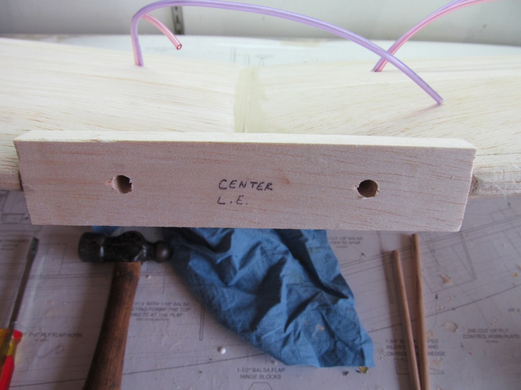
I temp installed the dowels and then glued the center leading edge block in place. I started to plane the center leading edge to profile and went as far as I dared so the glue would dry.
Next is to profile the leading edge. Epoxy in the dowels, set the wing in the fuse cradle and drill and tap the hold down screws. I am waiting on glue to dry and am chomping at the bit to see it together for real for the first time.
If I can get this accomplished today I will post pictures. If not tomorrow.
Glenn

Turning the corner in the build. The manual wants me to install the wheel covers now and the machine guns. I am going to wait to do these until I am just about ready to cover the wing with fiberglass. I may wait on the wheel covers until after the maiden. We will see how I feel. Anyway, The next step is to install the wing to the fuselage.
I temp installed the dowels and then glued the center leading edge block in place. I started to plane the center leading edge to profile and went as far as I dared so the glue would dry.
Next is to profile the leading edge. Epoxy in the dowels, set the wing in the fuse cradle and drill and tap the hold down screws. I am waiting on glue to dry and am chomping at the bit to see it together for real for the first time.
If I can get this accomplished today I will post pictures. If not tomorrow.
Glenn

