


Corsair with DLA 128 4 Cylinder Build
 06-02-2015, 06:26 PM
#151


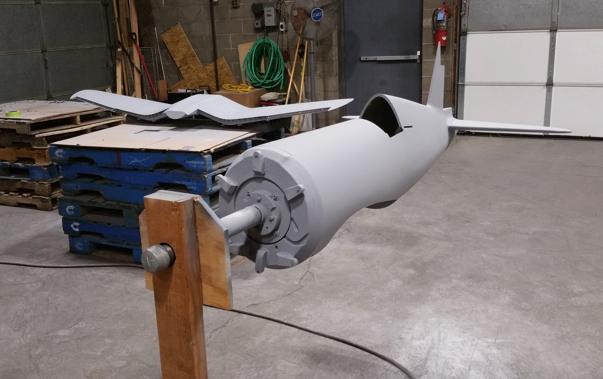
I bought a gallon of lacquer based primer surfacer. This primer goes on heavy, dries quickly and is very easy to sand. I know that it is old technology and the preferred choice is for urethane 2 part primer surfacer. It cures very hard and it is also easy to sand. My big issue with it is that like to leave it in the gun so that I can re-apply as necessary without the worry of it kicking off and turning solid in the gun.
I gave two coats on everything sanding in-between and a third coat on the wing to fill in the weave of the 1 oz. glass cloth. The last sanding was with 220 grit paper.


I gave two coats on everything sanding in-between and a third coat on the wing to fill in the weave of the 1 oz. glass cloth. The last sanding was with 220 grit paper.
 06-02-2015, 06:27 PM
#152
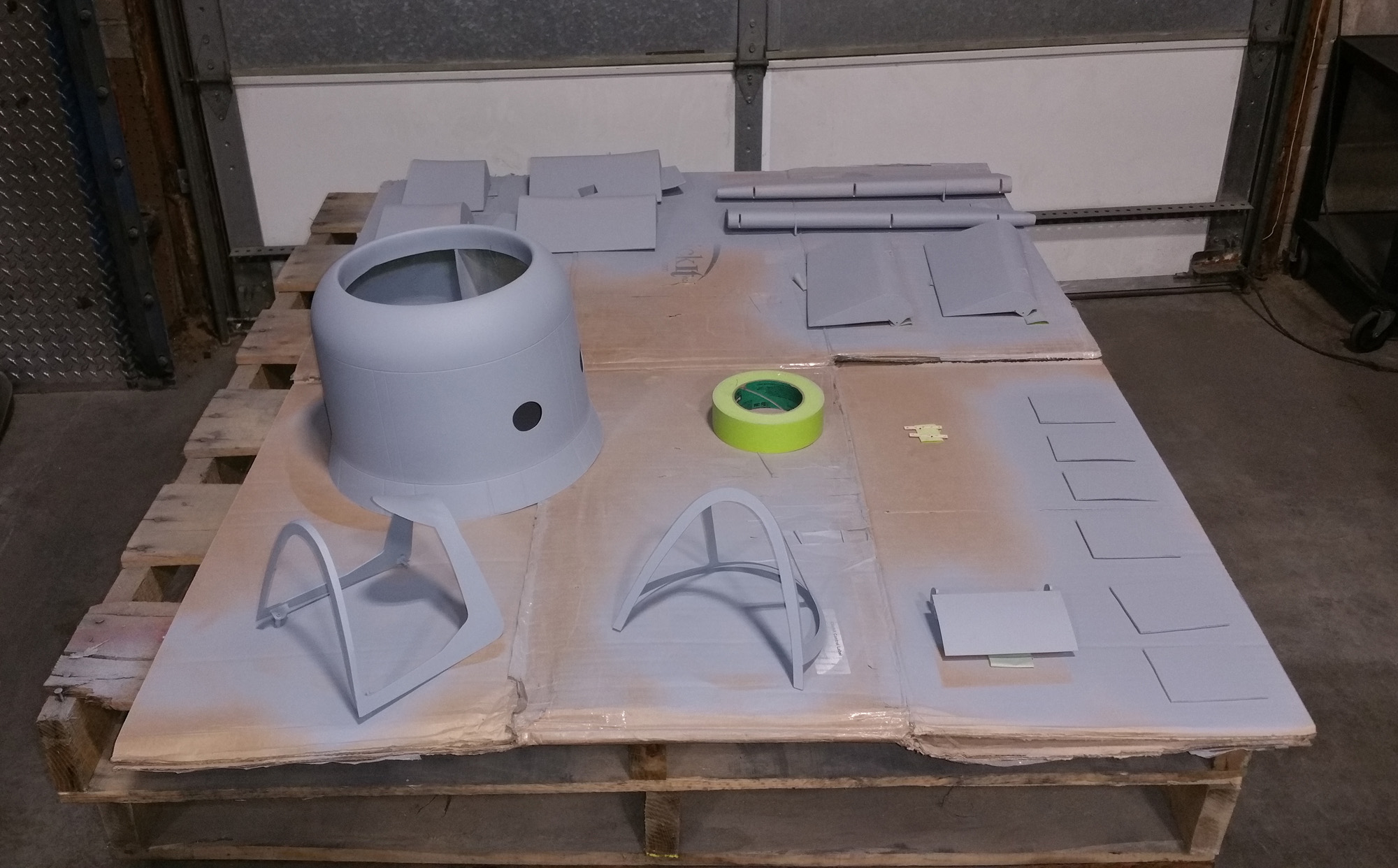
I have marked the panel lines that I want to show as a groove and used 1/32” black crepe ChartPak Tape. The next primer to fill around the tape will be Klass Kote Epoxy primer. After it is dry I will peel off the 1/32” tape and it will leave small grooves behind. To simulate the rib stitching reinforcing tape I am using 3/32” wide tape but I will leave it on under the primer and color coats to simulate the raised rib tape.
In the wheel well openings I added some plastic rectangle stock to give a hint of the corrugations that are inside the full size Corsair.


In the wheel well openings I added some plastic rectangle stock to give a hint of the corrugations that are inside the full size Corsair.
07-04-2015, 07:09 AM
#153
As you can probably tell progress is going slower now that flying season is in full swing. On off days I have been busy masking and painting.
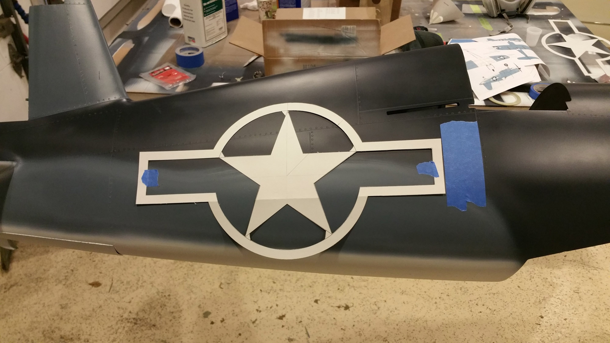
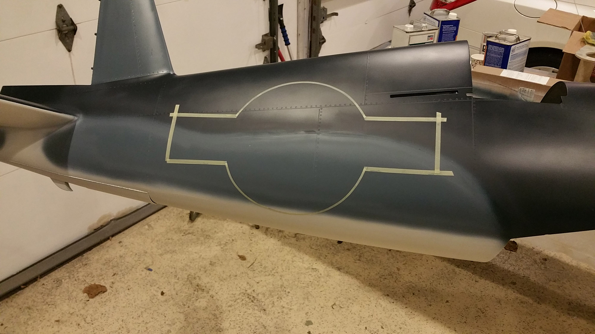
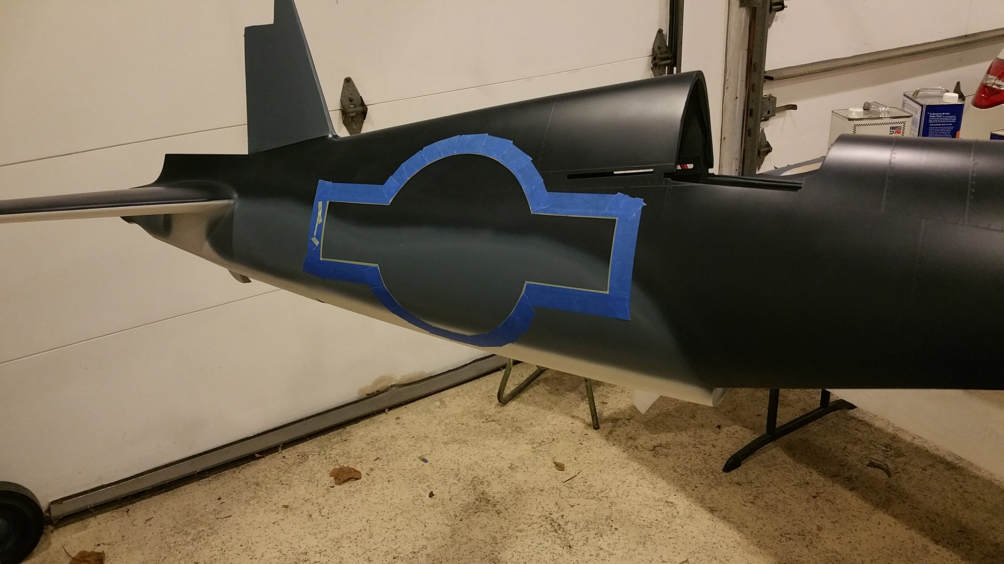
Getting back to a very early discussion about what technique to use to paint the soft edge between the three colors, I went with a method recommended by a club member. I taped it off to make a hard edge and then sanded the edge down when it dried. Then I used my airbrush to make the soft edge. This method avoids all the overspray that with my other projects. If I did it again I would use the round foam tape to make the semi-soft edge and then use the airbrush to get the effect I was after.
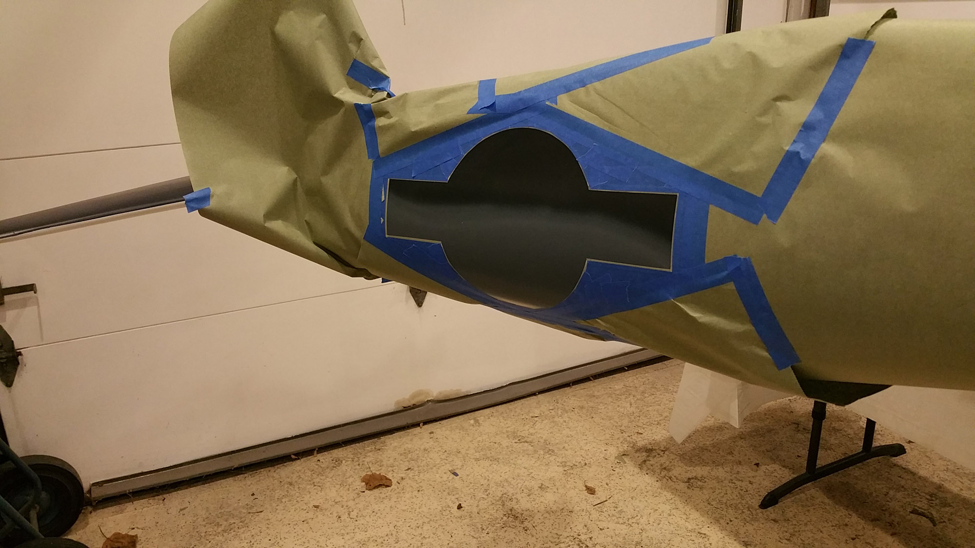
To make the stars and bars I made a heavy paper template, taped it in position and traced the outline with a pencil. Then I used 3M striping tape followed by masking tape and paper. I found that paint masks for the large image are hard to manage.
One small problem I discovered with the Klass Kote epoxy paint is that when you paint white over red the red bleeds thorough. You can see the pink in the photo. No matter how may coats I shot it turned to pink before my eyes. Nate at Klass Kote recommended a light coat of clear over the white to seal it. Then after the clear dries shoot more white. That worked well.
I am currently in the process of adding the markings. I have a paint mask coming to do the 18 Japanese kill markings and a vinyl graphic for the Marines Dream image.
After that I will shoot everything with a coat of semi-gloss Klass Kote clear and start re-assembling.


Getting back to a very early discussion about what technique to use to paint the soft edge between the three colors, I went with a method recommended by a club member. I taped it off to make a hard edge and then sanded the edge down when it dried. Then I used my airbrush to make the soft edge. This method avoids all the overspray that with my other projects. If I did it again I would use the round foam tape to make the semi-soft edge and then use the airbrush to get the effect I was after.
To make the stars and bars I made a heavy paper template, taped it in position and traced the outline with a pencil. Then I used 3M striping tape followed by masking tape and paper. I found that paint masks for the large image are hard to manage.
One small problem I discovered with the Klass Kote epoxy paint is that when you paint white over red the red bleeds thorough. You can see the pink in the photo. No matter how may coats I shot it turned to pink before my eyes. Nate at Klass Kote recommended a light coat of clear over the white to seal it. Then after the clear dries shoot more white. That worked well.
I am currently in the process of adding the markings. I have a paint mask coming to do the 18 Japanese kill markings and a vinyl graphic for the Marines Dream image.
After that I will shoot everything with a coat of semi-gloss Klass Kote clear and start re-assembling.
07-30-2015, 03:49 PM
#155
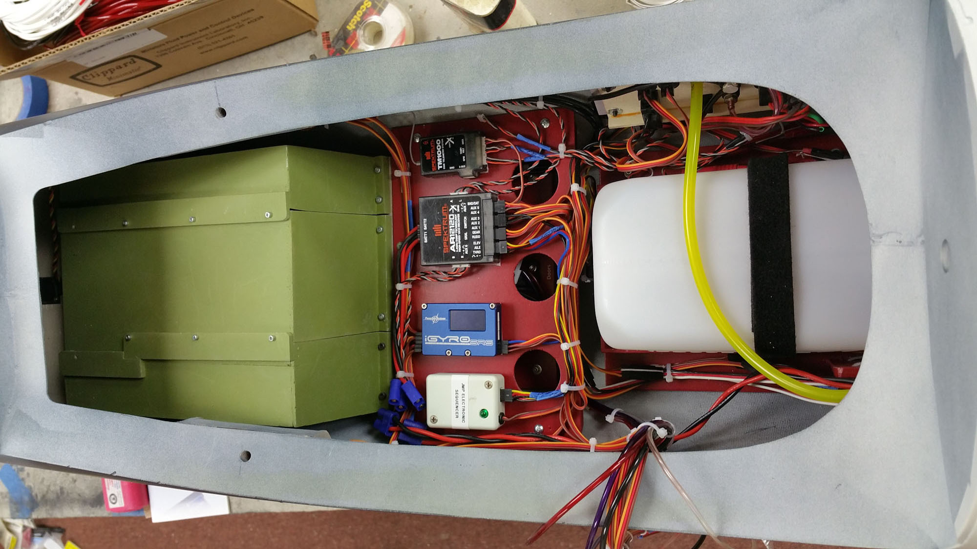
I’ve been busy assembling the fuselage. The wiring and air hoses were straight forward but the “L” bracket I made to hold the fuel tank, ignition modules, throttle and choke servo and all three batteries was really tricky to install. I had to remove the access panel and adjust one of the batteries and then it slid in place.
I am using a Spektrum 12 channel power safe receiver with the telemetry module. I have the rear cylinder temp and rpm sensor connected to it. I also have a temp probe on one of the forward cylinders but it is not connected to the module as it can only deal with one thermal probe at a time. I will see which one is hottest and use that for the telemetry.
I will be using a Power box iGyro three axis gyro for stability. I have had very good results with this in other planes I built.
I added a small electronic sequencer for the gear and doors. I was going to use the sequencer in the DX18 but I ran out of channels. I realized that I could not put the steering and rudder on the same channel because when the tail wheel is retracted there is no room for it to pivot as it just peeks through the doors. I have them on two channels now and when the gear is up the steering is disabled.
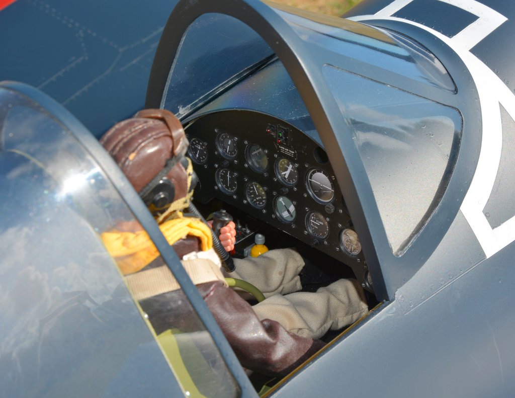
What I was really worried about was installing the cockpit with the canopy and pilot in place. It was kind of like building a ship in a bottle except I wasn’t sure it would fit. Luckily I left the forward canopy off and it just wiggled in with no room to spare. I’ll show a top view later after the canopy glue is set.


I am using a Spektrum 12 channel power safe receiver with the telemetry module. I have the rear cylinder temp and rpm sensor connected to it. I also have a temp probe on one of the forward cylinders but it is not connected to the module as it can only deal with one thermal probe at a time. I will see which one is hottest and use that for the telemetry.
I will be using a Power box iGyro three axis gyro for stability. I have had very good results with this in other planes I built.
I added a small electronic sequencer for the gear and doors. I was going to use the sequencer in the DX18 but I ran out of channels. I realized that I could not put the steering and rudder on the same channel because when the tail wheel is retracted there is no room for it to pivot as it just peeks through the doors. I have them on two channels now and when the gear is up the steering is disabled.
What I was really worried about was installing the cockpit with the canopy and pilot in place. It was kind of like building a ship in a bottle except I wasn’t sure it would fit. Luckily I left the forward canopy off and it just wiggled in with no room to spare. I’ll show a top view later after the canopy glue is set.
08-10-2015, 03:39 PM
#158
There are still a few details to take care of such as the balance and Navigation Lights and the wing radiators left to do but I have wanted to start the engine to see what it sounds line. The prop I am using is something I had and it is too small for the engine. It is a CF 27” x 10 pitch. I will probably take my first flights with this as it is advisable to not put too much of a load on the engine before it is broken in. I thought I had a good plan to baffle the engine for efficient cooling but I really wanted to see the results. It took a number of flips to draw fuel up the first time but once I got a pop I turned off the choke and the next flip it was running. I am very happy to report that the temp was around 160F which is very cool. I did some higher speed busts and the hottest I go it to go was 185F. Running it around 2500 rpm was enough to see the cylinder temp come back to the 160F mark. This is very cool especially for a new engine. Top RPM on my second run was 6,900. I am sure it will unload quite a bit in the air. The final prop will be a 3 blade carbon fiber but I want to see the flying results with this prop to determine the best size to get.
Here is a short video and a photo at the field. The Spektrum telemetry is showing 179 degrees F. The engine has a really cool growl sound when it revs up and is supper smooth running. No adjustment was done to the carburetor except to remove the idle stop screws so that I can kill it with low throttle.
By the way the total weight so far before balancing was 40.5 lbs.
https://www.youtube.com/watch?v=46SP1Tz0OCA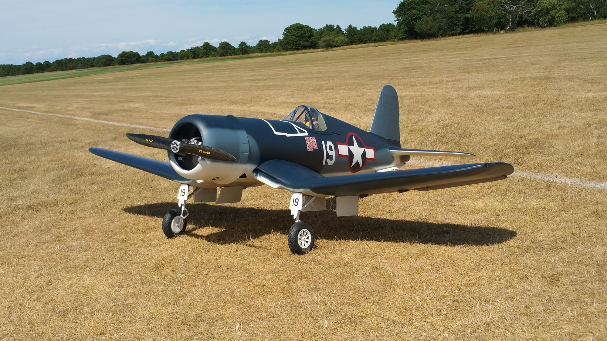
08-10-2015, 03:41 PM
#159
When assembling the wing to the fuselage I was getting dents in the area of the wing radiator. The fuselage saddle in the fiberglass version has very sharp edges where you rest the leading edge of the wing to make up the connectors. The solution I came up with was to make a cap to go over the leading edge with an elastic strap to keep in in place.
A little heat from my heat gun took out the dents.
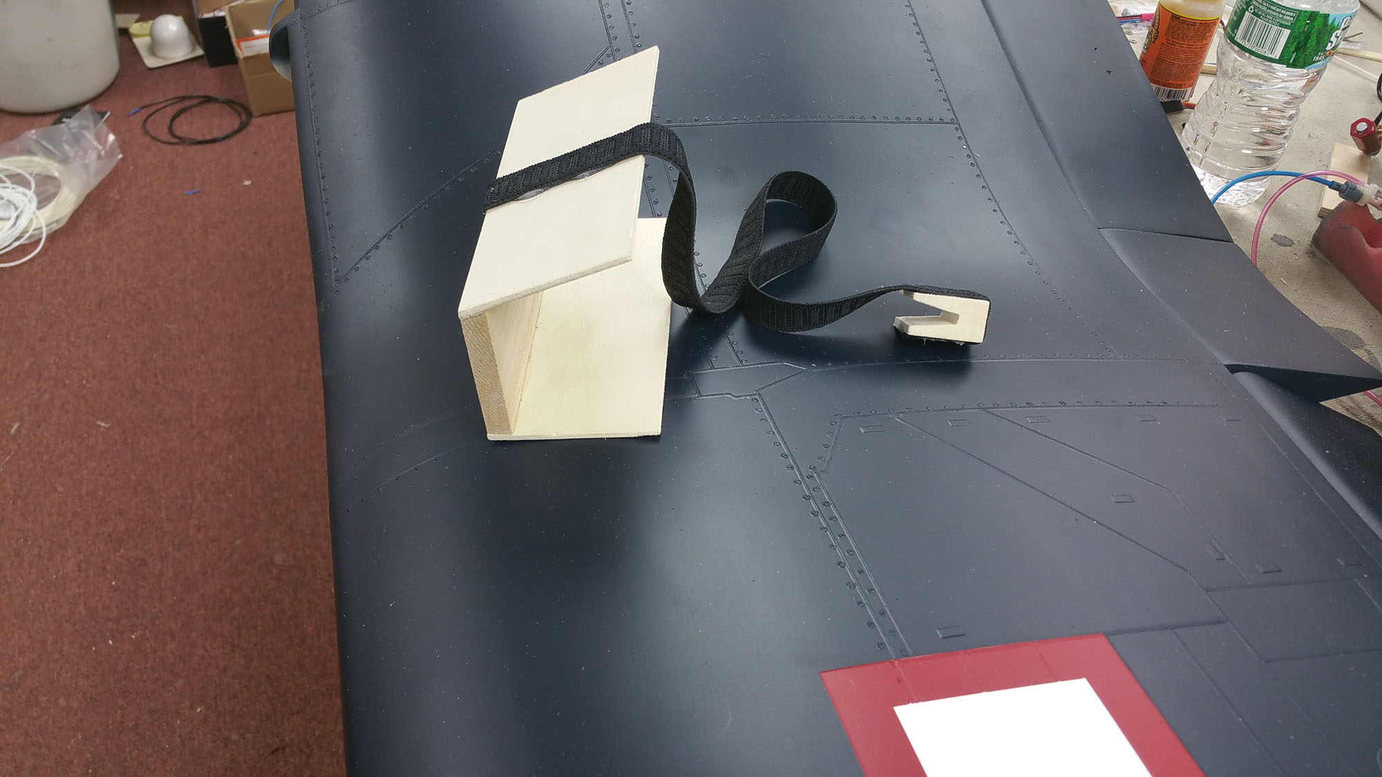

A little heat from my heat gun took out the dents.
08-20-2015, 05:10 PM
#160
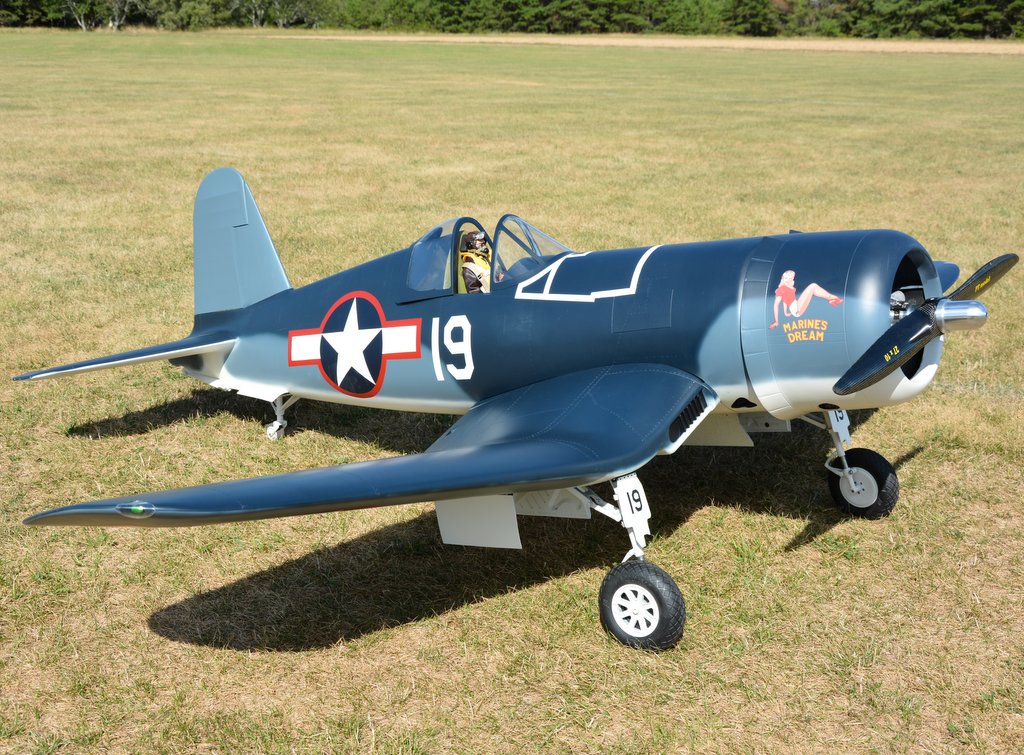
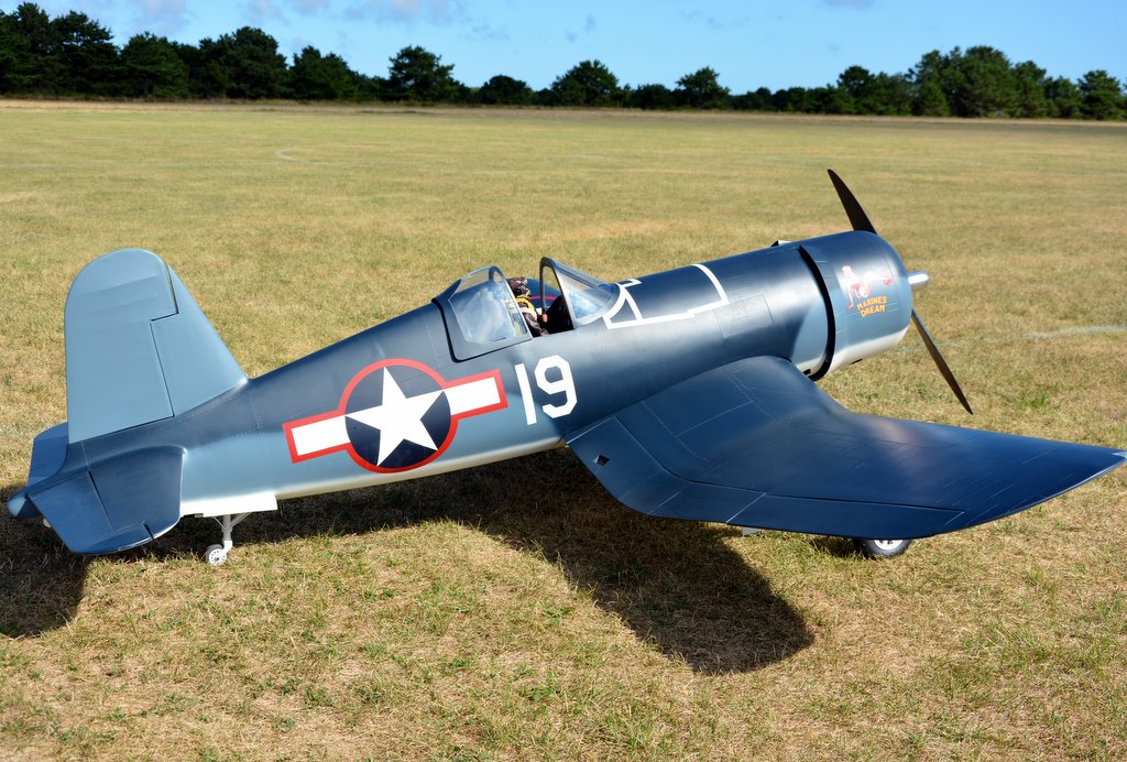
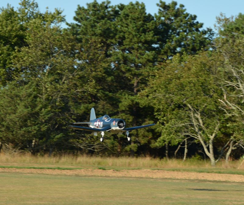
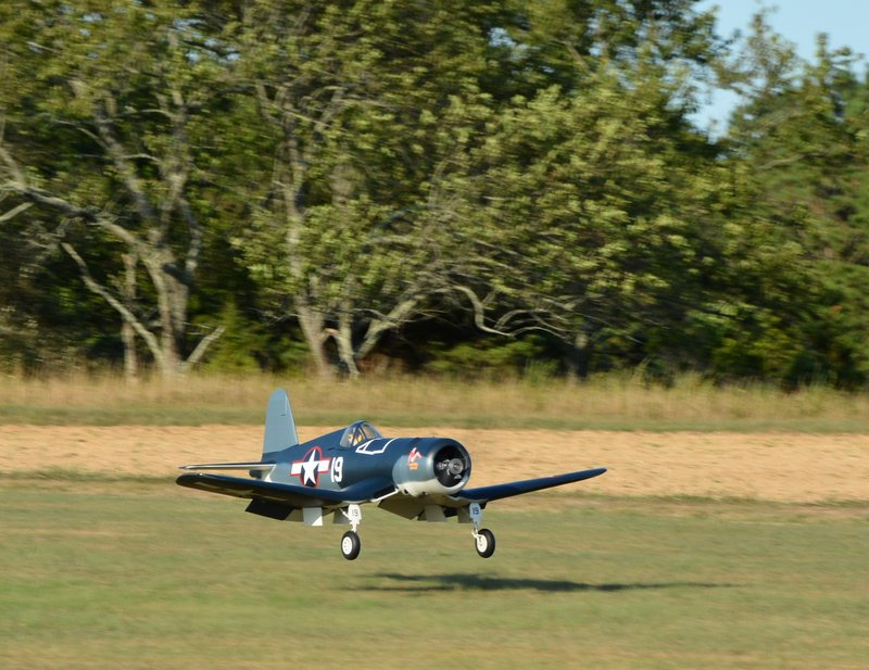
It’s been a week now and I have not been able to fly the Corsair. I tried twice but I have been having gear issues. It seems to stem back to a leaking air cylinder in the tail wheel retract. Air will leak past the seals in the plunger. This causes a pressure drop and the mains do not operate properly. I have a new cylinder on order to arrive tomorrow. I also added a second air tank to give me more cycles. I gave more clearance to the main gear doors. I made the clearances originally too tight. The clearances were working fine in my air-conditioned work shop but did not do so well out in the high heat and humidity of our field. I think I have it all sorted out now and weather permitting Sunday will be my next attempt. My good friend Sal Calvagna took some photos of the finished plane complete with my nose art. I plan to go with a 3 bladed prop but I will do my first flights with the 27-10 two blade you see in the photos.


08-21-2015, 04:25 AM
#161

My Feedback: (16)
Join Date: Apr 2002
Location: Macedon,
NY
Posts: 301
Likes: 0
Received 0 Likes
on
0 Posts
Lou been following your thread. Great work. I too have been fighting air leaks on my Top Flight Giant F4U but finally got rid of them yesterday. hope to do my maiden soon. John T. Corsair Brotherhood#96
08-21-2015, 05:05 AM
#162
Hi John:
Thanks for your comment. When it leaks through the cylinder it is really hard to find if you have not seen that before. The air will be hissing out of the valve. You might wonder how that is possible but if the down line is pressurized and it leaks through the cylinder then the up line will have air coming out and it exits through the valve. When the valve is in the down position the up line is open to the atmosphere otherwise the cylinder would not move. I had my valve out and apart, tried a new one but it kept hissing out air until I realized what was going on. To make matters worse I filled the cylinder with oil in hopes that the seals would swell. It did seal and it sort of stopped the leak but then the cylinder would stick in the up or down position if left for a while. Next time I will check the cylinders when I get them. After you have them for a year no one would accept a return.
Good luck with your maiden. Let me know how it goes.
08-27-2015, 05:57 AM
#163
The first flight went amazingly well. The goal was to trim it out and monitor the temperature of the engine. The DLA-128 is very cool running in fact I am wondering if I have too much air flow over the cylinders. While flying it never got over 160 degrees F I was just a bit over half throttle and never opened it up even at takeoff. The heavy nose weight I had on the prop shaft is just about right. I am going to make a heavy insert for my Tru-Turn Hub that will be about 3/4 lbs total weight on the engine shaft. I also added 2 lbs of lead shot to the inside leading edge of the cowl.
Trimming was minor with two clicks of down and about 4 clicks of right aileron. With the gear up it was flying very nicely. I set my rates up pretty much as the plans call for and I left them that way for the flight. Once I get to wring it out I may decide to change it slightly.
The wind was mostly down the runway and the landing was very smooth. I noticed no trim change at half flaps with the gear down. On full flaps it was very slightly trying to balloon. I adjusted my transmitter so that I had a very slight down elevator on full flaps for the future.
The iGyro needs have the plane trimmed out before making gain adjustments. The first flight was with the gyro mode switch off.
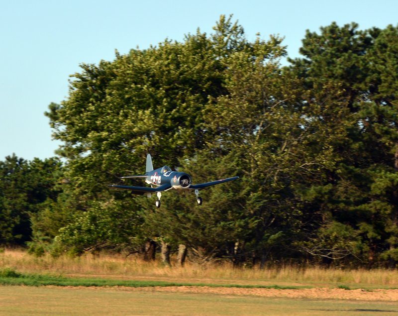
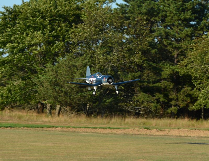
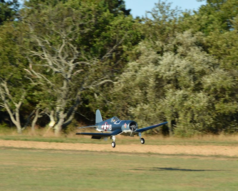
I made my photographer buddy watch the temps and be there in case I needed huge trim corrections so there are not many photos. Here is the landing though.


Trimming was minor with two clicks of down and about 4 clicks of right aileron. With the gear up it was flying very nicely. I set my rates up pretty much as the plans call for and I left them that way for the flight. Once I get to wring it out I may decide to change it slightly.
The wind was mostly down the runway and the landing was very smooth. I noticed no trim change at half flaps with the gear down. On full flaps it was very slightly trying to balloon. I adjusted my transmitter so that I had a very slight down elevator on full flaps for the future.
The iGyro needs have the plane trimmed out before making gain adjustments. The first flight was with the gyro mode switch off.
I made my photographer buddy watch the temps and be there in case I needed huge trim corrections so there are not many photos. Here is the landing though.
08-31-2015, 08:16 PM
#164
One of my fellow club members put together a really cool video of my forth flight on the Corsair this past Sunday. Thanks Matt.
I am really impressed with the engine. I was advised by a few that it would be just too much power for the plane but it is a fantastic combination. On that last fight I was able to confirm the CG by going up at a 45 degree angle and rolling inverted. I let go of the sticks and the plane stayed right on its path. The CG is spot on at 5 5/8 inch aft of the leading edge of the main wing.
https://www.youtube.com/watch?v=Q1zn-OepC5E&feature=em-share_video_user
 09-05-2015, 06:42 PM
#168
Thanks Billy.
I'm still trying to figure out what prop would be best on this beast. On my last flight I was getting 7,950 rpm with a three blade 25 x 12 carbon fiber prop. That is way to high an RPM. I just bought at 26 x 14 carbon fiber 3 blade. I calculate that it should unload in the air to a max of 7,200 and let me go a little faster.
Normally it takes off at just above half throttle and it and cruses around at half power very well.
I can idle it down to 1,100 with no problem so the extra pitch should be slow enough to land nicely.
10-06-2015, 03:08 PM
#169
I found the perfect prop for the Corsair. It is a carbon fiber 3 blade Semi-Scale Biela 26” dia x 14” pitch prop. I was a little concerned about the high pitch and if it would slow down enough on landing. However it is not an issue at all. The engine idles very well at just over 1,000 rpm and lands nicely with just a touch of power. The prop weights about 1/2 of a pound more than my 3 blade 25-12 prop and I was able to remove the weight I made that went inside the aluminum prop hub.
The maximum RPM in the air is 6,500 now down from nearly 8,000 with the 25x12 prop. It does take longer to rev up and I would not recommend this prop for an aerobatic plane but for a scale warbird it is just perfect.


The maximum RPM in the air is 6,500 now down from nearly 8,000 with the 25x12 prop. It does take longer to rev up and I would not recommend this prop for an aerobatic plane but for a scale warbird it is just perfect.
10-13-2015, 06:29 AM
#172
Hi Billy:
I’ve been flying the Corsair a lot. With the iGyro it is rock solid and it almost looks surreal as it does not move at all in a flyby. The engine is so solid and smooth it is easy to set a nice power setting for landing without it changing. I’m still on the factory needle valve setting which appears to be just perfect.
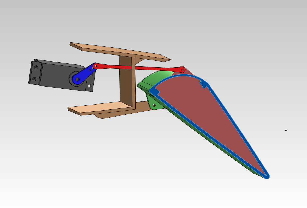
I got a chance to check the flap deflection for you. I have a clip on gauge where you set it at 0 degrees and then you can read out the control surface deflection. So when the flaps are up I set it at 0 and at full down flap it is 37 degrees. For half flap I used half of the full flap setting. The elevator compensation is very small. At half flaps I have no compensation and full flap is probably equivalent to two clicks of down elevator. I’m using the DX18 with the flap system for flap control. This is similar to JR’s 12X transmitter.
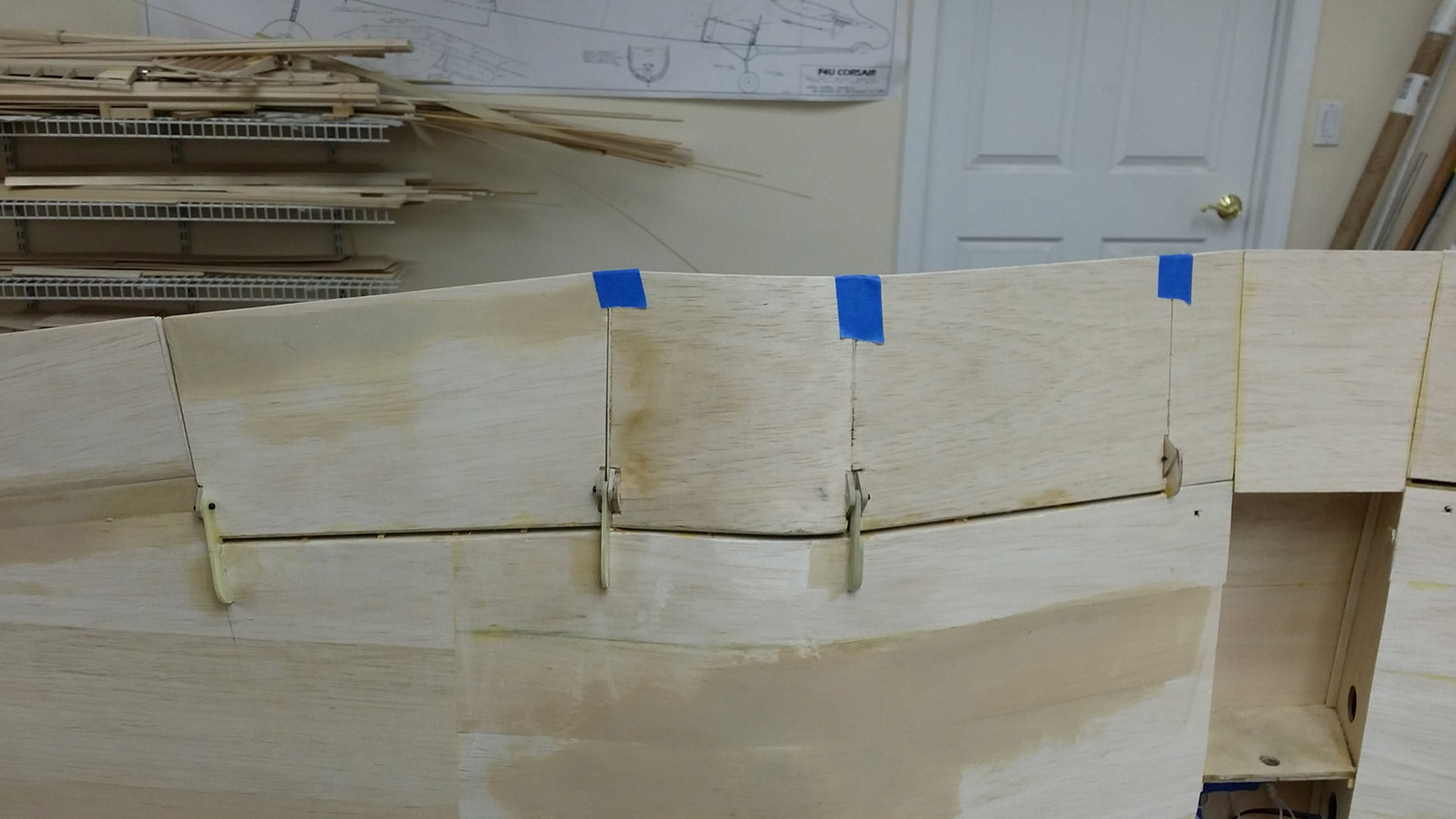
Here are a few photos of the hinging geometry and construction on the flaps. If I had it to do over again I would have made a separate pair of hinge tabs for each flap segment rather than sharing them as the plans call out but it seems to work fine with no slop so far.


I’ve been flying the Corsair a lot. With the iGyro it is rock solid and it almost looks surreal as it does not move at all in a flyby. The engine is so solid and smooth it is easy to set a nice power setting for landing without it changing. I’m still on the factory needle valve setting which appears to be just perfect.
I got a chance to check the flap deflection for you. I have a clip on gauge where you set it at 0 degrees and then you can read out the control surface deflection. So when the flaps are up I set it at 0 and at full down flap it is 37 degrees. For half flap I used half of the full flap setting. The elevator compensation is very small. At half flaps I have no compensation and full flap is probably equivalent to two clicks of down elevator. I’m using the DX18 with the flap system for flap control. This is similar to JR’s 12X transmitter.
Here are a few photos of the hinging geometry and construction on the flaps. If I had it to do over again I would have made a separate pair of hinge tabs for each flap segment rather than sharing them as the plans call out but it seems to work fine with no slop so far.
10-13-2015, 06:24 PM
#173
Congrats on your job man. It's like pulling teeth to get those flaps in order / remember Iam framing two of these bugers up at same time and have read each and everyone of the threads from to the UK! I went with G 10 hinges hysold in place for strength. I was worried about snapping m off when moving One plane and g10 slider for first two flappers which is ok , I can get 45-50 degrees of throw now so I should be ok
10-28-2015, 05:59 PM
#174
Junior Member

Join Date: Aug 2006
Location: EastMeadow, NY
Posts: 26
Likes: 0
Received 0 Likes
on
0 Posts
Hello Lou, its Joe MacDougall from the field. Great build thread Lou. I copied the pics of your engine baffling I think I need to do it for my DLA 64 in my Pitts Python. I love seeing that Corsair fly.
https://www.youtube.com/watch?v=hGoq93iX2_U
https://www.youtube.com/watch?v=hGoq93iX2_U
Last edited by Thunderthud1; 10-28-2015 at 06:52 PM.
10-28-2015, 06:43 PM
#175
Hi Joe:
The DLA 64 is very similar to my engine. It has two 32 cubic inch cylinders where mine has 4. However there is a big difference in how to cool a twin vs a quad engine. In an opposed twin the correct method is restrict the air that comes in to only pass through the top and bottom cylinder fins. It is important to realize that the center of the propeller is not efficient at moving air. That being the case it is essential to plan the shape of the cowl so that the exit of the cooling air is designed so that it is sucked out. Create a low pressure zone in the rear of the cowl to do this. The air that is being sucked out of course must pass though the cylinder fins which in turn cool the engine.
In a quad it is similar only in creating a low pressure zone in the rear of the cowl but if air that comes in goes across the top and bottom of the cylinder from the front to rear then rear cylinders will over heat. In a quad it is best to have the air pass from top to bottom and restrict it to going through all 4 cylinder fins.
The Pitts Python full scale had a round radial engine. The best approach is to make a baffle to block all air coming in the front of the cowl with two openings that are the size and shape of the cylinders. One cylinder will be forward of the other so have the baffle so that it also steps back. That way all the air coming in has to go through the fins. Air will take the path of least resistance. If you have large openings around the cylinders the same amount of air will flow through but now most of it will not pass through where it is needed.

