


Corsair with DLA 128 4 Cylinder Build
 09-02-2014, 09:38 AM
#51

My Feedback: (60)
Join Date: Dec 2001
Location: Litchfield Park,
AZ
Posts: 7,677
Likes: 0
Received 25 Likes
on
23 Posts
Hi Chad:
I am planning to fully sheet the wings and then simulate covered ribs. i am thinking about using raised ribs over the sheeting, possibly with chart tape or 1/32" thick plywood strips and then using a filler with credit card to simulate fabric concave dips. I'm not really sure yet how I am going to go about it but definitely it will be fully sheeted. I'll have to experiment to see what looks best.
I am planning to fully sheet the wings and then simulate covered ribs. i am thinking about using raised ribs over the sheeting, possibly with chart tape or 1/32" thick plywood strips and then using a filler with credit card to simulate fabric concave dips. I'm not really sure yet how I am going to go about it but definitely it will be fully sheeted. I'll have to experiment to see what looks best.


 09-08-2014, 02:07 PM
#53
Last weekend I went to Sanford Maine to the Horizon Jet Rally. At the airport there was a full size Corsair and an Avenger. I got a bunch of photos of the Corsair and some close ups of the wings fabric covering. I now realize that all you see is a slight indentation where the rib is and the pinking reinforcement tape. There is a heavy coat of paint over it all. It does not look that pretty but I guess it will be scale.
Kennebunkport (the Bush's home town) is just down the road from where we were and George Bush Sr. signed the prop of the Avenger. I thought that was very cool.


Kennebunkport (the Bush's home town) is just down the road from where we were and George Bush Sr. signed the prop of the Avenger. I thought that was very cool.
09-24-2014, 05:39 PM
#54
Continuing on the wing much of the 3/32 sheeting is bent quite a bit. I like to use Titebond II wood glue were possible and CA only when it is absolutely necessary as I need to wear a respirator when I use it. My method is to spray both sides with Ammonia and weight down the sheeting until it is dry. Then I glue it in place with additional weights. I feel that the wood is not under stress that way which may help to keep the wing straight.


On the plans Nick layed out a pattern to cut the sheeting in the forward center area. I pre-bent the wood here as well but used CA as it would have been difficult to weight the wood down until is set.


On the plans Nick layed out a pattern to cut the sheeting in the forward center area. I pre-bent the wood here as well but used CA as it would have been difficult to weight the wood down until is set.
09-24-2014, 05:40 PM
#55
On the under-side I made up servo wire extensions for the two aileron servos and four flap servos. I also ran string so that I can pull through air hoses to the gear and gear doors. I like to purchase my own bulk cable and JR style connectors and make up the servo extensions myself. I found that the best quality connectors are from MPI. They appear to have a good amount of gold plating on the contacts and crimp very well. I use 22 gage wires throughout.
I used a dab of silicone adhesive where the cable comes out of the last rib hole so that it will be where I expect it when I cut out the servo access panels after it is all glassed.

I used a dab of silicone adhesive where the cable comes out of the last rib hole so that it will be where I expect it when I cut out the servo access panels after it is all glassed.
09-24-2014, 05:40 PM
#56
One thing that I am trying out is to have both sides of my servo access panels glassed. The outside surface is easy but on the inside I added 1 oz of glass cloth with Z-Poxy resin in the area where the access doors will be. This panel with go on the outboard wing section just in front of the flaps and ailerons.

09-24-2014, 05:44 PM
#57
Here I have the leading edge sheeting done. The top sheeting is fairly flat at the wing tips but on the bottom side from the last two ribs to the tip there is a healthy bend. I used ammonia here and weighted it down with magazines and clamps. When dry I glued it with Titebond-II.


Here I have that rear panel from above glued in place in a similar fashion. You can see where I had to trim a slot for my G10 flap hinge.

Here I have that rear panel from above glued in place in a similar fashion. You can see where I had to trim a slot for my G10 flap hinge.
10-15-2014, 03:42 PM
#60
I sheeted the bottom of the wing and cut out the ailerons and flaps. The ailerons were easy to cut out in-between the spars I just used a razor saw between the ribs and a thin flat saw on ends. The flaps were another issue. I neglected to add the cut shown on the plans to the leading edge of the flaps when I cut out the ribs. The flaps are basically cut out with small section on the top and bottom attaching it to the end of the ribs. I could have made this cut using a scroll saw before building the wing and this would have made life much easier. Then I would only have to cut a �” or so from the top and bottom to free the flaps.
Here you see the bottom of the wing with the �” cap strips on the trailing edge of the wing by the flaps. I also added extra gussets in the area of the flaps to give the thin balsa trailing edge more support.


Here you see the bottom of the wing with the �” cap strips on the trailing edge of the wing by the flaps. I also added extra gussets in the area of the flaps to give the thin balsa trailing edge more support.
10-15-2014, 03:46 PM
#62
Here is a photo of the some of the flaps after I added the 1/16” thick balsa leading edge. Ammonia helped to soften the wood for the tight bend.

After sanding the overlap of the 1/16 leading edge and cleaning up the edges the flaps are starting to take shape.


After sanding the overlap of the 1/16 leading edge and cleaning up the edges the flaps are starting to take shape.
10-15-2014, 03:49 PM
#63
The trailing edge of the wing by the flaps is very delicate. When the wing is glassed and the flaps are installed it will be somewhat protected from dings. However, I wanted to have a nice thin edge here so I fitted a 1/32” aircraft ply strip as reinforcement in this area. I needed to recess the 3/32” balsa sheeting by 1/32” so that the trailing edge strip would lie flush. I made a sanding tool using some plywood and two layers of 60 grit sand paper.

Then I used it to sand a recessed groove area on the trailing edge.

Then I used it to sand a recessed groove area on the trailing edge.
10-15-2014, 03:51 PM
#64
Since it is curved I had to make a template for 1/32” strip so that it would fit in nicely and I cut it out of large aircraft ply sheet with an x acto knife.

I glued it in place with Tite-Bond-II and clamped it to set up.

Here you see the finished results with some filler spread over the seam.

I glued it in place with Tite-Bond-II and clamped it to set up.
Here you see the finished results with some filler spread over the seam.
10-15-2014, 03:53 PM
#65
I am now fitting the ailerons in place. Before I glued the �” cap strip on the trailing edge of the wing I pinned the over-sized strip to the wing and sanded the top side flush with the top of the wing. Then removed it and I tack glued 2 layers of 1/32” plywood to the top side and pined it back on the wing with the plywood strips now flush with the top of the wing. Basically the trailing edge strip was 1/16” below flush with the top of the wing. Then I sanded the bottom of this strip flush with the bottom of the wing. Now when I glued it on it is centered and will be exactly 1/32 below flush on the top and bottom. I can later add a 1/32” aircraft ply strip here top and bottom in the recess to form my aileron pocket.

It sounds more complicated than it really is. I should have taken a few more photos but hopefully it will be clearer in future posts when I add the cap strips and hinge the ailerons.
It sounds more complicated than it really is. I should have taken a few more photos but hopefully it will be clearer in future posts when I add the cap strips and hinge the ailerons.
Last edited by flyn2high; 10-16-2014 at 04:47 AM.
10-28-2014, 03:57 PM
#67
Thanks Bob. Just taking my time and enjoying the process.
The next two photos will illustrate the method I used to build up the pocket for the ailerons. You can see the two 1/32” plywood strips on the top and bottom of the pocket and they are flush to the top and bottom sheeting.


The next two photos will illustrate the method I used to build up the pocket for the ailerons. You can see the two 1/32” plywood strips on the top and bottom of the pocket and they are flush to the top and bottom sheeting.
10-28-2014, 04:03 PM
#70
I needed to smooth out the balsa sheeting in the bent area of the wing. I also wanted a better fit on the flap segments to the trailing edge of the wing. I used West System 410 Microlight Filler along with their 406 Colloidal Silica. It is mixed into the West Epoxy Resin until it is the thickness of peanut butter. The filler cures to the consistency and weight of balsa and sands great. The Colloidal Silica gives the filler properties such that it resists sagging.
To sand the curved wing I made a sanding block out of foam so it would conform to the curved shape and attached a couple of hotel room keys so that I could bear down without the end of the sand paper digging in.


To sand the curved wing I made a sanding block out of foam so it would conform to the curved shape and attached a couple of hotel room keys so that I could bear down without the end of the sand paper digging in.
10-28-2014, 04:05 PM
#72
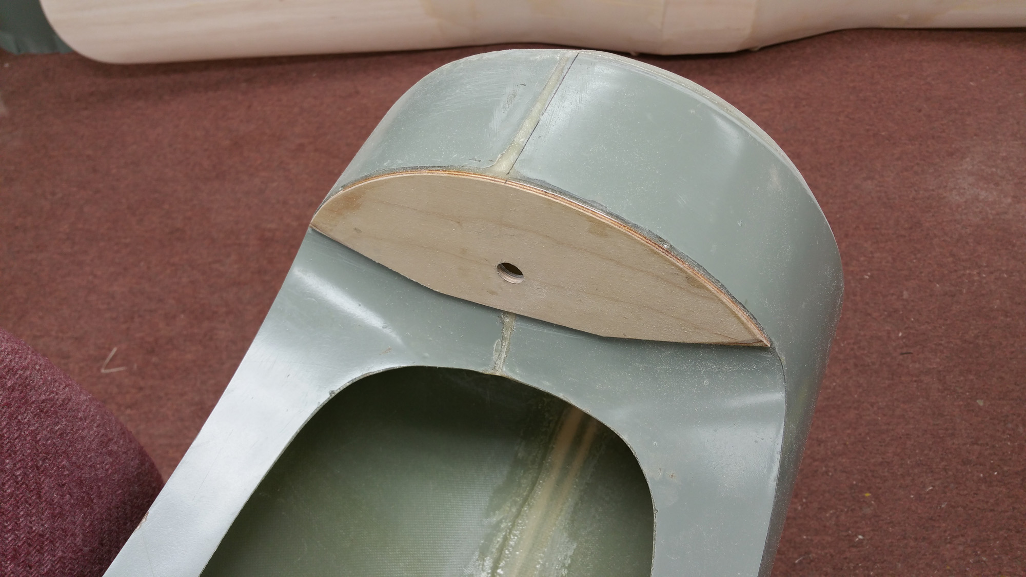
I fitted rather heavy duty maple screw down blocks into the fuselage sides with plywood gussets. I lined up the predrilled �-20 tap drill holes in the wing and drilled through into the maple blocks and then tapped them for �-20 threads. I made a maple �” dia post for a strong the leading edge support. In my case there was a bit of clearance between the front of the wing and the fuselage so I mounted my forward support between the wing and fuselage with 1/8” aircraft ply and 45 min epoxy.

10-28-2014, 04:07 PM
#73
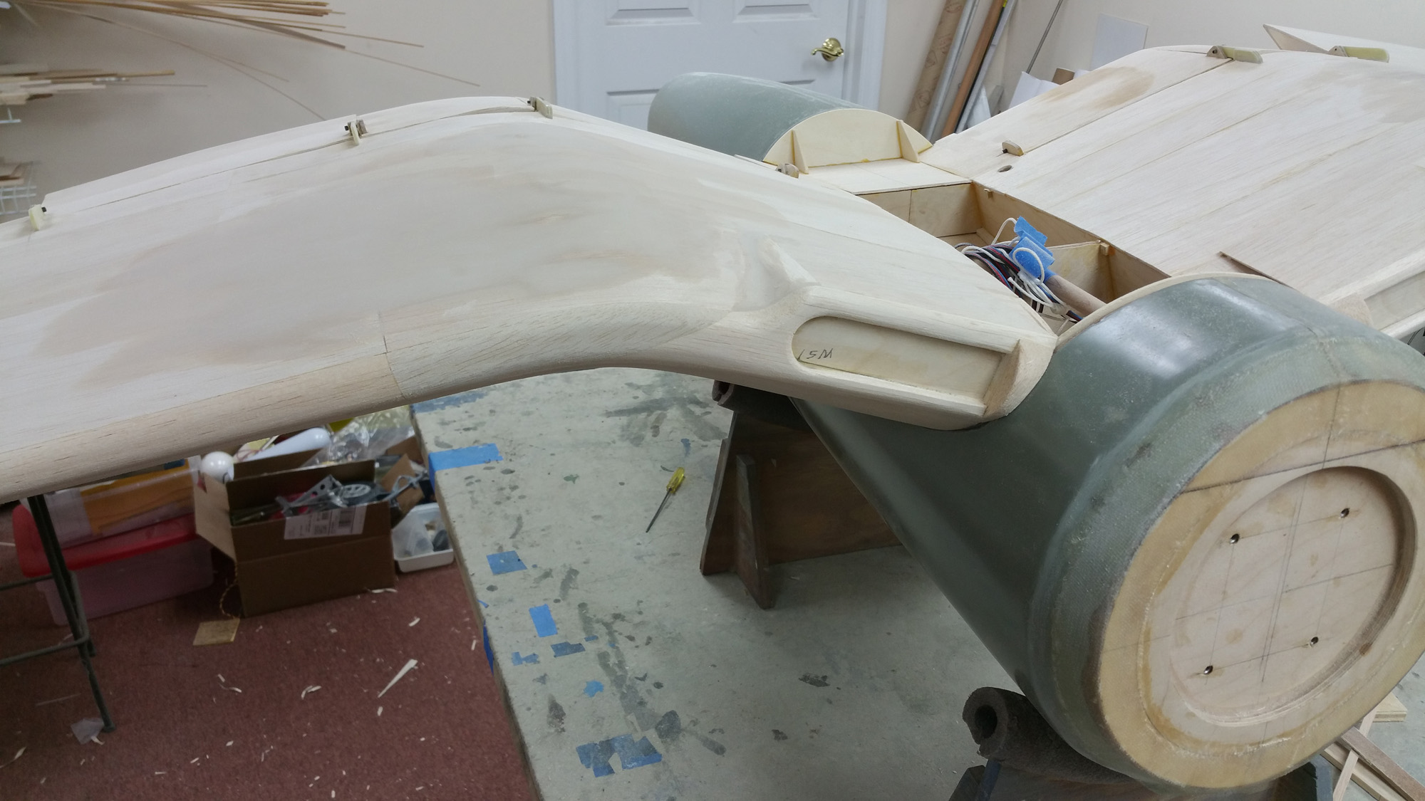
I added a belly pan support at the front and back of the wing. Then I fitted in the supplied fiberglass belly pan. I needed to sand the edges so that it was a good fit to the wing. I do not want to hard mount it until after the wing is glassed.


10-28-2014, 04:11 PM
#75
Next I sanded the curvature on the leading edge and continued to fill in the sheeting here and there to correct any irregularities. A little more filling and sanding and the wing will be ready for fiberglass.
I will be using 1 oz glass cloth on all the glassed surfaces with Z-poxy finishing resin. I started on the flaps and ailerons.


I will be using 1 oz glass cloth on all the glassed surfaces with Z-poxy finishing resin. I started on the flaps and ailerons.