


Cessna 152 - 2,7meter
 02-17-2017, 01:09 AM
#26
Senior Member
Thread Starter

Join Date: Nov 2016
Posts: 146
Likes: 0
Received 0 Likes
on
0 Posts
The continuation of the vertical stabilizer, the rudder.


This time, for alignment and fixing of the items I used toothpicks.
It was an experiment and I liked the result, in the future I will use this solution.
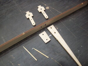


A rocking chair is mounted on two M3 screws.
Remembering the previous experience (glider) chair is set after the film, since the protruding parts are interfere with the wrapping.


This time, for alignment and fixing of the items I used toothpicks.
It was an experiment and I liked the result, in the future I will use this solution.
A rocking chair is mounted on two M3 screws.
Remembering the previous experience (glider) chair is set after the film, since the protruding parts are interfere with the wrapping.
 02-18-2017, 07:27 AM
#27
Senior Member
Thread Starter
Join Date: Nov 2016
Posts: 146
Likes: 0
Received 0 Likes
on
0 Posts
The rudder hangs on 3 hinges, aluminum axis with diameter of 2.4 mm.


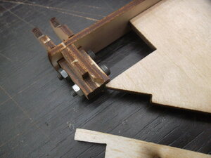
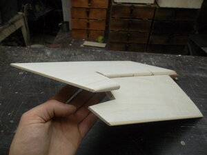
Assembly of the stabilizer. The servos are mounted on hatches.


The place of fastening of the hatch.


The stabilizer is sheeted with balsa 1.5 mm thick fully.


Assembly of the stabilizer. The servos are mounted on hatches.
The place of fastening of the hatch.
The stabilizer is sheeted with balsa 1.5 mm thick fully.


 02-20-2017, 01:48 AM
#29
Senior Member
Thread Starter
Join Date: Nov 2016
Posts: 146
Likes: 0
Received 0 Likes
on
0 Posts
Resin like a rose, maybe she's still stiffness will gain some time, but the process is already possible.

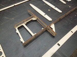
To brace there's a pattern, it is to mark the holes and length.

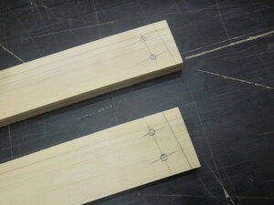

After assembling the stabilizers tried on hatches and it turned out that the washers I glued is not correct. Now I put a new washer where necessary.


That's where they should be!
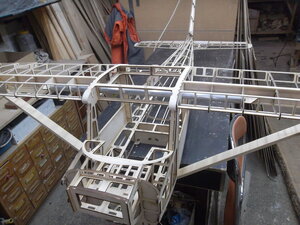
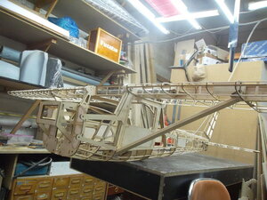
And of course, the long-awaited moment, gathered all in a heap. Control surfaces yet no, but everything else is connected as it should be.


To brace there's a pattern, it is to mark the holes and length.
After assembling the stabilizers tried on hatches and it turned out that the washers I glued is not correct. Now I put a new washer where necessary.
That's where they should be!
And of course, the long-awaited moment, gathered all in a heap. Control surfaces yet no, but everything else is connected as it should be.


 02-24-2017, 11:25 PM
#33
Senior Member
Thread Starter
Join Date: Nov 2016
Posts: 146
Likes: 0
Received 0 Likes
on
0 Posts
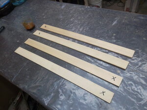
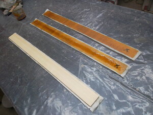
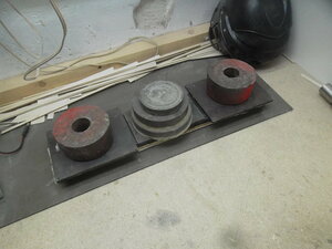
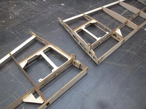
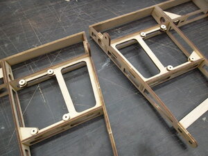
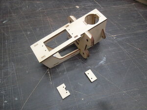
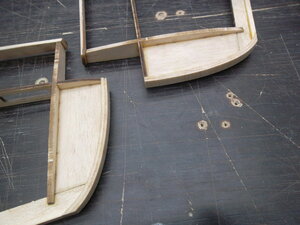
I make details of fastening struts on the floats.

It turned out very convenient to fasten the workpiece to the table!


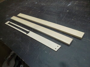
Fixing the front of racks (1 pair).

Fixing the rear struts (2 couples).

It turned out very convenient to fasten the workpiece to the table!
Fixing the front of racks (1 pair).
Fixing the rear struts (2 couples).


 02-27-2017, 08:36 AM
#35
Senior Member
Thread Starter
Join Date: Nov 2016
Posts: 146
Likes: 0
Received 0 Likes
on
0 Posts
Trial installation of the lantern (from Whatman) was unsuccessful.

From the outset, I would to do.


As planned, the upper part should be opened completely for easy access to the screws fastening the tail boom.
But after fitting it turned out that it looks awful, and even access to the screws more than enough.
So it was decided to add a lining under the rear window. The drawings made some changes, added new items.


In fact, it turned out even better than I'd like, instead of slatted braces that I had planned for the paste hardness, the new parts have created this extra loop and rails are not needed.


lantern Pattern needs to be corrected, continue to work.


From the outset, I would to do.
As planned, the upper part should be opened completely for easy access to the screws fastening the tail boom.
But after fitting it turned out that it looks awful, and even access to the screws more than enough.
So it was decided to add a lining under the rear window. The drawings made some changes, added new items.
In fact, it turned out even better than I'd like, instead of slatted braces that I had planned for the paste hardness, the new parts have created this extra loop and rails are not needed.
lantern Pattern needs to be corrected, continue to work.
02-28-2017, 10:15 AM
#36
Senior Member
Thread Starter
Join Date: Nov 2016
Posts: 146
Likes: 0
Received 0 Likes
on
0 Posts
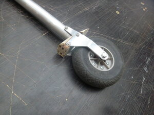
In this part, the chassis mounted fairing.


The front desk, 20mm aluminum tube. diameter.


Chassis plug, duralumin D16T 2mm thick.

I wanted to make a simple knot, that without turning and milling operations.


The plug attached to the rack cogs M3


Front chassis diameter of 90mm. Axis diameter of 5mm.


The front desk, 20mm aluminum tube. diameter.
Chassis plug, duralumin D16T 2mm thick.
I wanted to make a simple knot, that without turning and milling operations.
The plug attached to the rack cogs M3
Front chassis diameter of 90mm. Axis diameter of 5mm.
03-01-2017, 10:53 AM
#37
Senior Member
Thread Starter
Join Date: Nov 2016
Posts: 146
Likes: 0
Received 0 Likes
on
0 Posts
He graduated from the front rack to collect.

Establish a rack. All move right, goes up and down and rotated.

Installed parts shock absorber.


The resilient member in the damper fishing gum. Elasticity has not yet picked up.

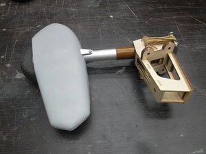
Sample Test hand instilled confidence, feels should be how to work.


Weight normal.

Establish a rack. All move right, goes up and down and rotated.
Installed parts shock absorber.
The resilient member in the damper fishing gum. Elasticity has not yet picked up.
Sample Test hand instilled confidence, feels should be how to work.
Weight normal.
03-02-2017, 09:40 AM
#38
Senior Member
Thread Starter
Join Date: Nov 2016
Posts: 146
Likes: 0
Received 0 Likes
on
0 Posts
The main chassis diameter of 110mm.
Somehow miraculously perfect fit screw M5 50mm long. on the smooth part of the wheel hub slides, carving fully engaged.
Grease for model helicopters (I had when the two helicopters), special grease for metal / plastic compounds. And as anther rubber gaskets removed from the hose to the mixer.

Under the cap rubber ring.

Nut screwed on to the end, under the washer rubber ring, the wheel is very smooth spin and do not hang out. Thread length and the smooth part came just perfect.


He noted and cut holes in the fairing process.


standard mount.


And of course more to tie model.


Stuffed into the cabin 9kg iron.

load racks curved. They milled from duralumin D16T 4mm thick. on the idea they have to bounce, because of this I did not use 6mm duralumin to absorb.
Hopefully bending no reaches the non-return.


The fairings are not held securely, they hang out in hand, struts added.


Now fairings are tough.


And I forgot to weigh them, realized this at home: D
Somehow miraculously perfect fit screw M5 50mm long. on the smooth part of the wheel hub slides, carving fully engaged.
Grease for model helicopters (I had when the two helicopters), special grease for metal / plastic compounds. And as anther rubber gaskets removed from the hose to the mixer.
Under the cap rubber ring.
Nut screwed on to the end, under the washer rubber ring, the wheel is very smooth spin and do not hang out. Thread length and the smooth part came just perfect.
He noted and cut holes in the fairing process.
standard mount.
And of course more to tie model.
Stuffed into the cabin 9kg iron.
load racks curved. They milled from duralumin D16T 4mm thick. on the idea they have to bounce, because of this I did not use 6mm duralumin to absorb.
Hopefully bending no reaches the non-return.
The fairings are not held securely, they hang out in hand, struts added.
Now fairings are tough.
And I forgot to weigh them, realized this at home: D
Last edited by Faster Wind; 03-02-2017 at 08:15 PM.

 03-04-2017, 03:56 AM
#40
Senior Member
Thread Starter
Join Date: Nov 2016
Posts: 146
Likes: 0
Received 0 Likes
on
0 Posts
Glazing is made of a polycarbonate film with a thickness of 0.5mm.The attachment points on the pattern will be glued plywood lining.
Glued ledges of reechek, to overlay the lantern clung to the rim.


On the reverse side are glued lining.

On the front side only mounting holes and slot for towing a rail.

Unhook the glider mechanism is virtually the trailing edge of the wing.
Thanks to Vladimir Kulikov, he suggested that the place must have unhooked at the rear edge of the tug.


As planned, removing the glazing obtained unlimited access to the cockpit.
Glued ledges of reechek, to overlay the lantern clung to the rim.
On the reverse side are glued lining.
On the front side only mounting holes and slot for towing a rail.
Unhook the glider mechanism is virtually the trailing edge of the wing.
Thanks to Vladimir Kulikov, he suggested that the place must have unhooked at the rear edge of the tug.
As planned, removing the glazing obtained unlimited access to the cockpit.
 03-05-2017, 05:46 AM
#42
Senior Member
Thread Starter
Join Date: Nov 2016
Posts: 146
Likes: 0
Received 0 Likes
on
0 Posts
David Bathe thank you for your appreciation.
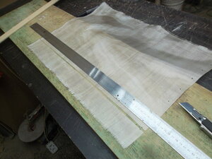
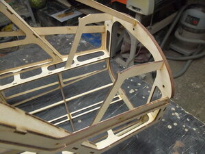
Prepared by the front part of the fuselage to the skin of balsa.


For the skin I have prepared 30 sheets, balsa 1.5mm.
each sheet was weighed. knowing the weight of the sheets I distribute them to the density on different elements.
Thick Balsa will go to the ribs and edges, on average forehead and fuselage, easy on the tailplane.

Prepared by the front part of the fuselage to the skin of balsa.
For the skin I have prepared 30 sheets, balsa 1.5mm.
each sheet was weighed. knowing the weight of the sheets I distribute them to the density on different elements.
Thick Balsa will go to the ribs and edges, on average forehead and fuselage, easy on the tailplane.
03-05-2017, 06:57 AM
#43
It's a pleasure, this is outstanding!
I can't understand why this thread is so quiet... I guess the vast majority of people are completely and utterly speechless.
This is a completely different league from the normal average giant scale "assembly" build.
What are you planning for power FastWind?
I can't understand why this thread is so quiet... I guess the vast majority of people are completely and utterly speechless.
This is a completely different league from the normal average giant scale "assembly" build.
What are you planning for power FastWind?
03-06-2017, 10:24 AM
#44
Senior Member
Thread Starter
Join Date: Nov 2016
Posts: 146
Likes: 0
Received 0 Likes
on
0 Posts
David, I have not decided yet.
I have two options: EME55 and ZDZ40
Sheathe began to tail.
The first the keel.

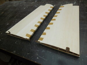
Patterns skin I prepare in advance, balsa sheets glued together superglue.

Slats under clothespins not stick, they want to pressed sheet without gaps.
From Titebond balsa swell and can vspuchilis between clothespins, the entire length of rail keeps trim level.

Rudder.

Rocking control system inserted after the stitched film.


For plumage selected sheets weighing 16-17 grams.
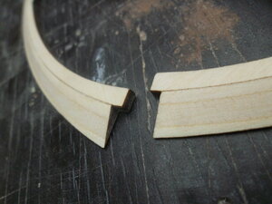
Rudder has a bend, it is quite small, but it is not fit. Fix the aluminum corner, thread bury inside. Corner deleted after pasting.


I have two options: EME55 and ZDZ40
Sheathe began to tail.
The first the keel.
Patterns skin I prepare in advance, balsa sheets glued together superglue.
Slats under clothespins not stick, they want to pressed sheet without gaps.
From Titebond balsa swell and can vspuchilis between clothespins, the entire length of rail keeps trim level.
Rudder.
Rocking control system inserted after the stitched film.
For plumage selected sheets weighing 16-17 grams.
Rudder has a bend, it is quite small, but it is not fit. Fix the aluminum corner, thread bury inside. Corner deleted after pasting.
03-06-2017, 02:21 PM
#45
Nice to hear you're not going to over power it. A couple of my friends have had a great deal of success using this classic Tony Clark G45 set up, with the super quiet muffer, internal carb intake modification to draw the air from inside the fuselage and hydro soft mount. It's been available for years, well tested. VERY quiet operation for a scale model... nice. Mind you, it doesn't have that wonderful electric start option like the EME... which with the correct big can muffler and a carb flute (amazing how much sound reduction you get by directing the air intake from inside the fuselage) and vibration reducing mount would be marvellous.
03-09-2017, 08:09 PM
#46
Senior Member
Thread Starter
Join Date: Nov 2016
Posts: 146
Likes: 0
Received 0 Likes
on
0 Posts
Thank you David.
The keel is ready for the film.


The final element of the leading edge of the rudder compensator.


The rudder is ready for the film.


Axle - aluminum spokes 2,4 mm. Diameter.

Vertical tail assembly. The keel and stabilizer will be removable.


The keel is ready for the film.
The final element of the leading edge of the rudder compensator.
The rudder is ready for the film.
Axle - aluminum spokes 2,4 mm. Diameter.
Vertical tail assembly. The keel and stabilizer will be removable.


 03-11-2017, 06:17 AM
#48
Senior Member
Thread Starter
Join Date: Nov 2016
Posts: 146
Likes: 0
Received 0 Likes
on
0 Posts
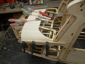
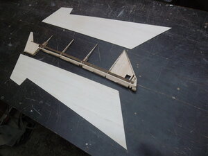
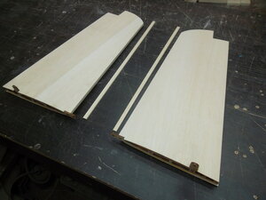
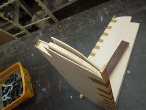
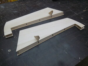
Stabilizers are ready for plating. All edges are sewn on the right angle.


Cutting patterns.

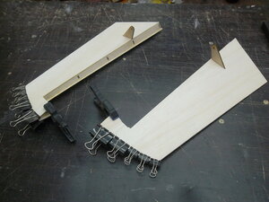
This photo shows that the skin on the tip is not glued.
This place will be glued afterwards, otherwise the balsa will warp and do not press against the ribs inside the stabilizer.

On the front edge of the skin clamped with clothespins through the rail, so the casing is held exactly over the entire length.


Cutting patterns.
This photo shows that the skin on the tip is not glued.
This place will be glued afterwards, otherwise the balsa will warp and do not press against the ribs inside the stabilizer.
On the front edge of the skin clamped with clothespins through the rail, so the casing is held exactly over the entire length.

 03-15-2017, 09:26 AM
#50
Senior Member
Thread Starter
Join Date: Nov 2016
Posts: 146
Likes: 0
Received 0 Likes
on
0 Posts
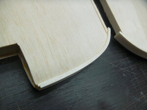
The ending, like on the stabilizer, is sealed at the end.


The horizontal plumage is almost ready.

Weight of the left stabilizer.
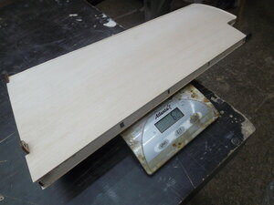
Weight of the right stabilizer.
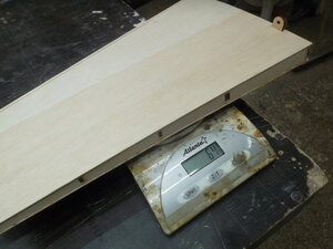
Weight of of the right elevator.

Weight of the left elevator.


