1/3 scale scratch build super cub
#26
Letís start building the top center section of the wing/cabin.
Cut the 1/4 x 1/4 square balsa stock to size for the bottom stringers. In the photo, you can see I made the back two solid from one side to the other.
Take the two inside WC1 ribs and mark the outline of where they will be attached to the upper cabin bracing. Take ribs WC1 and pin in place. Use triangle to get the outside rib straight. Use the template to get the correct angle for the inner ribs. The inside rib will lean to the inside.
Now cut the top 1/4 x 1/4 balsa stringer for the top.
Cut the 3/32 sheeting and apply to the top and bottom. The plans call for 5/16 aluminum tubes with 7mm carbon rods for the wing tubes. 7mm rods can be purchased from several locations on line. I went with carbon arrow shafts and made fiberglass sleeves for them. Instructions on The Cub Den on making fiberglass sleeves. You can see above the sleeves are installed. Now cover the top with 3/32 sheeting and install the nose blocks. Shape the nose blocks and sand all sheeting.
#27
Now is a critical alignment time. Set the fuselage so the top of the cabin (window opening) is level. Insert the front wing tube so equal lengths are protruding on each side and clamp in place. Use the outline you traced on the inner ribs to help line up the center section. For reference, you should have 6 5/32 between the top of cabin and the bottom of the sheeting just below the front wing tube. The wing should read 2 deg of incidence.
One last step is to take a string from the center of the tail to both ends of the wing tube. It should be the same distance on both sides or you have a twist somewhere. When happy, glue with 30-min epoxy
One last step is to take a string from the center of the tail to both ends of the wing tube. It should be the same distance on both sides or you have a twist somewhere. When happy, glue with 30-min epoxy
#29
Time to start building the tail surfaces. Recommend Tight bond for all joints except balsa to balsa and I use med CA in this spot.
I personally like to make a form to bend my wood with. I cut the form from so 3/4 plywood I had laying around. I drill holes as feel needed for my clamps.
The outer surface is built from a layer of 1/16 spruce and then 3 strips of 1/16 balsa. I lay all my strips out, apply glue to one side of all except the last strip of 1/16 balsa. Stack and start at one end clamping and wrapping around the form.
Second set gluing now along with first set laying on top. Just for reference. Do the elevator in one setting and the stab in a second run due to length of material. Remove and trim all to the correct height.
#30
With the parts off the form, now itís time to attach them to the backbone. The 1/8 ply is attached in the middle of the parts so I use some scrap of 1/8 spruce to space the backbone as I glue and clamp.
For the stab, I use a hard balsa for the 1/2 x 3/8 trailing edge. Pin the leading and trailing edge in place. Cur the inner and outer rib from 3/8 x 3/8 balsa and glue in place.
For the 1/4 x 3/8 balsa ribs you will need to cut a slot for the 1/8 ply backbone.
Next add all the 1/4 x 3/8 balsa ribs. Look for a good fit but donít make to tight and distort the trailing edge. Now add the couple of 1/4 x 1/4 balsa supports. Remember to put 1/1/6 spacers under them. Now place the leading edged of the elevator. Again, I use a hard balsa for the 1/2 x 3/8 Place the trailing edge of the elevator in place. Add all the 1/4 x 3/8 balsa ribs. Look for a good fit but donít make to tight and distort the leading edge. For the 1/4 x 3/8 balsa ribs you will need to cut a slot for the 1/8 ply backbone.
#33
Now to hinge the elevator. Feel free to use whatever hinges you have. I like the big Dubro pined hinges. I cut slots and installed three hinges per side.
Time to add the brass tubing. We will be using 3/8 OD brass tubing.
The images below are for reference only. Please check the plans for measurements.
Mark 3/8 back from the outside edge along with marking 1/64 inches from front area. I have also marked the point we need to trim to.
Remove the 1/64 of wood from the front and cut the back line to the trim spot.
With a scrap of 3/8 brass I sharpen the end and add a couple saw teeth to the tub. Insert it into your drill and set to low speed
Start using your drill to shape and cut the wood.
Keep going till you hit the trim line.
Now trim and remove the wood at the trim line.
This is the finished product. A dowel looking protrusion. Trim this to match the plans.
#35
Merry Christmas to all , updating the post before the little one is up.
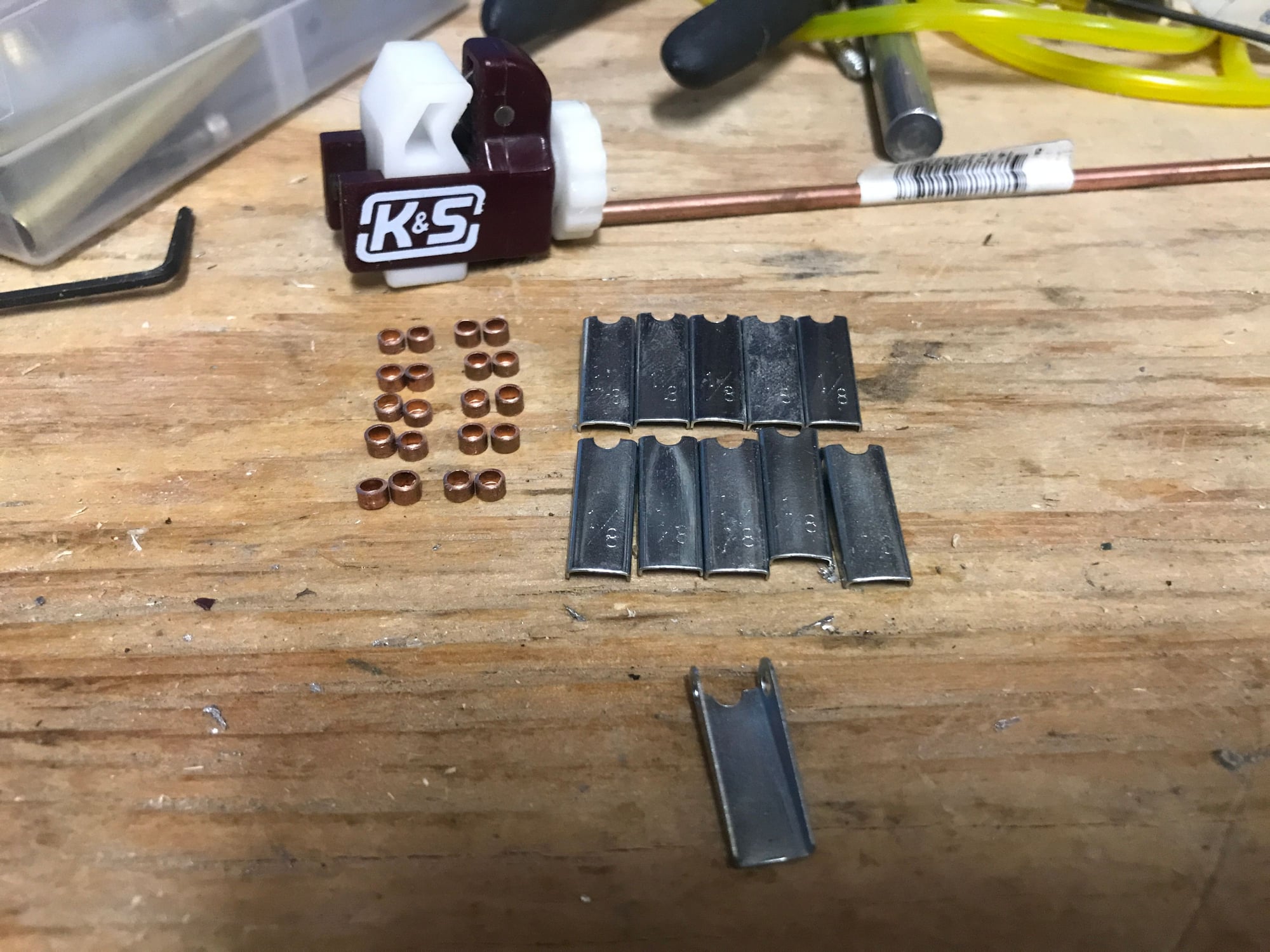
Cut 6 sections of 3/8 brass tubing at 2 inches long. Use a sanding wheel on a dermal and roughen the outside of the tube. Clean any bures from the inside.
11/32 brass tubing will slide inside of the 3/8 brass tubing. We use the 11/32 for the center section. Cut one 11/32 tube 4.85 inches long, for the front of the stab and one 2.4 inches long for the back of the stab. Cut another section 1.5 inch long for the elevator.
Next sand a hard wood dowel down so it will fit inside of the 11/32 tubing. Cut a length of 2.5 inches for the front, and 1 inch for the back tube. Insert the dowel in the tube and add a drop of then CA to glue it in.
Now letís assemble the stab / elevators. First insert the 6 sections of 3/8 brass tubing over the dowel looking protrusion. Next insert the 11/32 tubing into the 3/8 brass. Feel free to trim where needed to get everything to line up over the plans.
(photo was snapped after I took the stab apart.) With everything over the line up over the plans, mix some 30 min epoxy and apply a little where the tube meets the wood. Let dry, flip and repeat for the other side.
With the epoxy dry and the parts still line up over the plans. Letís drill a few holes. For where the 11/32 tubing is inside the 3/8 we will drill a 5/64 hole to accept a 2-56 bolt. This will be done 4 times.
Making note from the plans, Drill one 1/8 hole in the center of the back 11/32 tubing and two 1/8 holes in the front 11/32 tube.
#36
For the fin, layout the leading and trailing edge. Again, I use a hard balsa for the 1/2 x 3/8 for the trailing and medium hard for the leading edge.
Make the top from 3/8 x 3/9 balsa, insert the two 1/4 x 3/8 balsa ribs.
Next insert the 1/4 x 1/4 balsa supports. Remember to use 1/16 spacers under them.
As with the elevator, make a form to bend the wood around. On strip of 1/16 x 3/8 spruce and 5 strips of 1/16 x 3/8 balsa make the outside of the rudder. Unlike the elevator, the rudder has no 1/8 ply backbone.
Letís start by laying the 3/8 x 3/8 hard balsa out for the front post and for the boost tab on the rudder. Pin in place and glue. Next apply the outer section of the rudder, glue and pin in place. Follow up with the ľ x 3/8 balsa ribs.
Now to hinge the rudder. Feel free to use whatever hinges you have. Again, I use the big Dubro pined hinges. I cut slots and installed three hinges for the rudder.
Now back to the fuselage
#38
#41
Now to make the stab attachment points for the tail. This will give you an idea what the final product will look like. You can see the back one is rounded out to match the 5/16 brass. The front attachment is left flat. Now set you fuselage up so the top of the cabin in level.I make the rear one as the plans has it shown. For the front one you will need to make it so that the stabilizer sets level with the plane. For my cub the front mount came out just a 1/32 shorter than what was on the plans. Also, check that you get it squared up to the fuselage. Also use a section of fishing line from the center of the cabin back the back corners of the stabilizer to check that the tail is square to the fuselage. For the tail insert the ply to the bottom, with 4-40 blind nut inserted. For the front insert two 4-40 blind nuts from the bottom.
#42
Now to attach the fin. Using my laser, I strike a line vertical and align it with the fuselage. Glue the back of the fin to the fuselage, and add gussets as shown. For the front add the proper support to the front of the fin. With the fuselage still set on the datum line, the back side of the fin should be 90deg to the datum line.
#43
Now letís finish the cap strips to the turtle deck area. Clamp where needed.Next make the top cap strip from 1/4 x 3/8 spruce. I use a router bit in my dremel in my router stand to round the top over. Now attach the cap strip and clamp where neededInsert the 5/16 dowel or square for the upper back seat support. I went with square balsa. You may need to lightly spread the fuselage apart to insert it. She is starting to look like a super cub now!


