


SM 1/7 Scale F-14 Build

 02-19-2015, 08:13 PM
#77

Thread Starter

You are correct sir I meant to say 3mm, thanks for the catch. I did get a little surprise today which I was totally not expecting! I got a notification from DHL of a delivery tomorrow!!!!! If this is what I think it is then my new nose, stab and missing parts should be here tomorrow!!!!!so build crazy weekend since its suppose to snow and rain, I guess SM got everything out the door prior to their holiday. I hope I can muster up some motivation, im starting to worry I may have more than just the flu. The lungs are bothering me and cause some aches still. so I hope I dont have pneumonia  I will try regardless and get the nose section going since the only thing left in the tail section is final stuff and adding those 3mm blind nuts for the aft rails
I will try regardless and get the nose section going since the only thing left in the tail section is final stuff and adding those 3mm blind nuts for the aft rails
02-24-2015, 10:56 AM
#78
Thread Starter
Well everything arrived and all looks good, I got all the missing parts and the wing bags. I hope to get back to building soon I seem to have lost some motivation ever since I got sick.
02-27-2015, 07:16 PM
#79
Thread Starter
Well I managed to get a little work done this evening, I am having to redo the hole pattern on the new nose it does not line up with the holes on fuse. Easy fix just a pain, the new nose didnt come with the front missile rail blind nuts or the nose gear hoes so I am having to add all those as well. I started on the rails so I can get that done and turn the jet back over, I am using this time to mount the aft rails and add the blind nuts inside the fuselage since I have the pipes and turbines out. Once this is done I will install the main tank and mount the nose in prep for the equipment, the only bad thing here is once the nose goes on I need to move everything to the garage. I will do a temp install that way I can remove the nose to move down stairs, but its just to cold to work even in the garage still.
Video of the work on the aft rails is uploading, I had to add the ply blocks inside for the bolts and missile mounts. Pretty simple just some hysol and eight square ply blocks


https://www.youtube.com/watch?v=GGsf...ature=youtu.be
Video of the work on the aft rails is uploading, I had to add the ply blocks inside for the bolts and missile mounts. Pretty simple just some hysol and eight square ply blocks
https://www.youtube.com/watch?v=GGsf...ature=youtu.be
02-28-2015, 10:32 AM
#80
Thread Starter
The rails are done and all the blind nuts are in a the hysol is drying. The back rails need a light sanding and painted which I will do when I paint the rest of the missiles. They are going to require lots of sanding, I have them all of them ready for sanding. I also glued on a brake line holder to the top of the saddle tanks to hold the brake line.


 Once the glue cures I will start on the nose, I normally don't use much in the lines of equipment trays but I managed to get some competition grade ply. This stuff is 1/8 ply but weights about the same as 1/4 in balsa sheet so its strong enough to hold everything but doesnt add much weight.
  I hate useless weight it drove me nuts adding a pound to my last project for balance LOL first time in over 25 years I have had to do that. Anyway lots to do so I will get back to it! cheers!
I hate useless weight it drove me nuts adding a pound to my last project for balance LOL first time in over 25 years I have had to do that. Anyway lots to do so I will get back to it! cheers!
03-01-2015, 07:22 PM
#81
Thread Starter
Slow going today, this is always the worst part for me, It takes me forever to decide on placement and how to arrange everything so it looks neat and easy for maintenance. I finally decide on one Large tank for the gear, one tank for the canopy/speed brakes/brakes and one for the gear doors. As for the debate on how many valves to use I am going to try two and three to see which gives the best push. The aft tray will consist of the turbines equipment and UATs The mid will hold the air valves and front will be radio stuff.
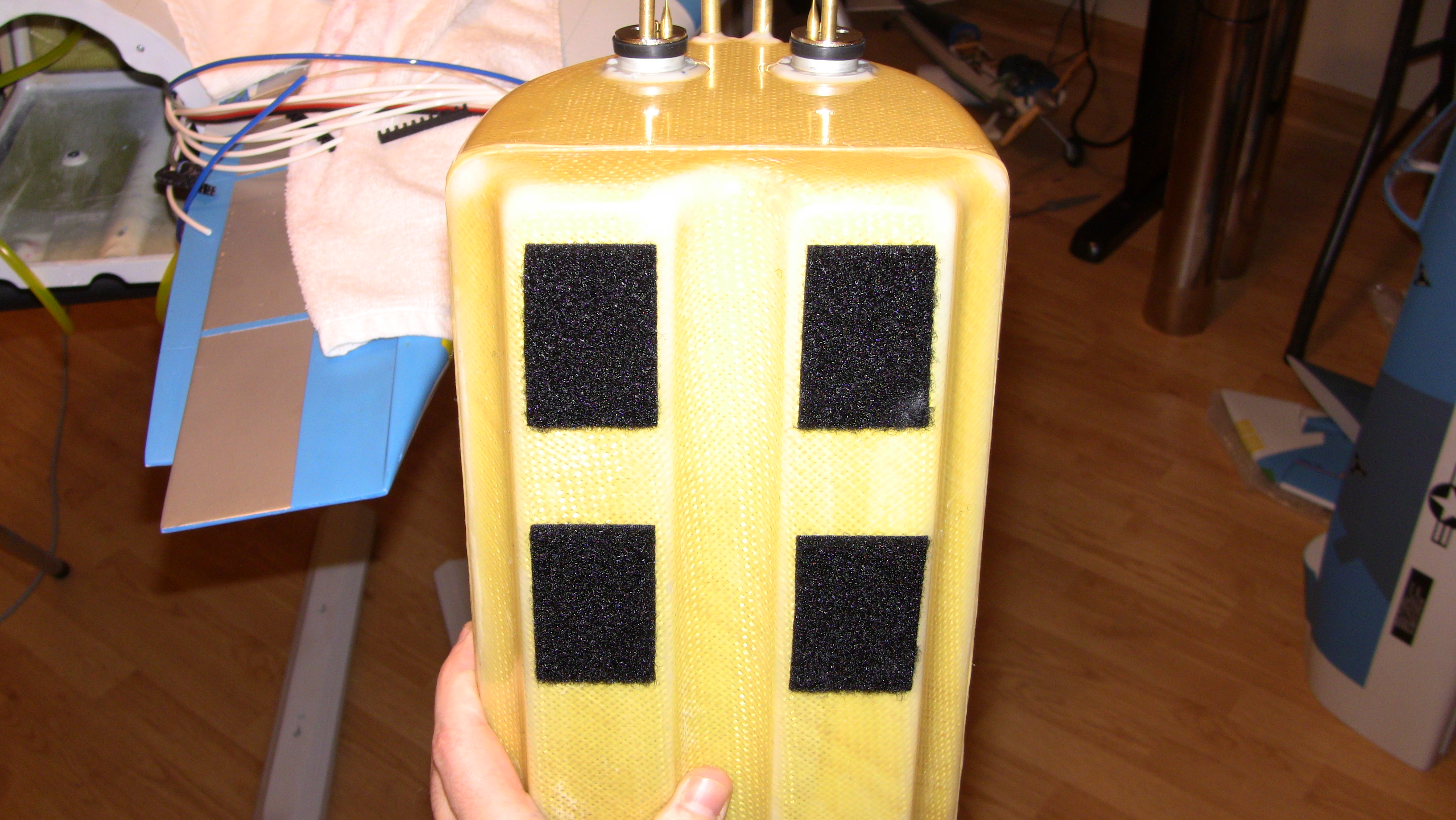
The nose took awhile to get aligned right and then I had to mount the nose gear, this required drilling some holes for the screws. The tank was just a simple velcro on the bottom with some fender foam on top to help secure it I made four squre ply blocks to act as a large washer for the joining screws. I did the typical lockwire on the lines and since the UAT lines were loose I did a triple lock wire to make sure it get s a good seal. Over board but why risk it right LOL As you can see there are a ton of things to arrange so this may take awhile.
 I need to switch gears and go back and install the rudder control horns and the slat horns followed by the rods for the wings and rudders. I will start this tomorrow probably and as things are drying continue to arrange the nose.
Two videos are uploading on the tube channel as well.


The nose took awhile to get aligned right and then I had to mount the nose gear, this required drilling some holes for the screws. The tank was just a simple velcro on the bottom with some fender foam on top to help secure it
I made four squre ply blocks to act as a large washer for the joining screws. I did the typical lockwire on the lines and since the UAT lines were loose I did a triple lock wire to make sure it get s a good seal. Over board but why risk it right LOL As you can see there are a ton of things to arrange so this may take awhile. I need to switch gears and go back and install the rudder control horns and the slat horns followed by the rods for the wings and rudders. I will start this tomorrow probably and as things are drying continue to arrange the nose.Two videos are uploading on the tube channel as well.
03-04-2015, 10:00 AM
#82
Thread Starter
I got the aft equipment board in, I really like the carbon tube aft support setup, its held in place by two servo screws in the front and a slide in type groove in the back. I hooked all the cables for the turbines into the ecus, a bit tight but once there in its a nice clean setup. Today I am going to get the air lines ran and the valves mounted, I had to order more air line holders since I ran out but I can still finish it up till the order arrives. I have a video uploading as well

 03-04-2015, 04:07 PM
#84
Thread Starter
just finished the air tray
03-04-2015, 09:03 PM
#85
Thread Starter
Another slow night, I had a couple of phone calls I had to make so it was slow going, I went with a three valve setup for my gear. I did this for a couple of reason and you will see why when everything is hooked up.
The board turned out nice and one servo runs all three robart valves. I hope it works, my only concern is the distance from the valve to the main gear. I have a small video showing the valve function uploading, time to call it a night but im snowed in tomorrow so a full day of building!!! Cheers!

The board turned out nice and one servo runs all three robart valves. I hope it works, my only concern is the distance from the valve to the main gear. I have a small video showing the valve function uploading, time to call it a night but im snowed in tomorrow so a full day of building!!! Cheers!
03-05-2015, 04:34 PM
#88
Thread Starter
Wim I am going to test to see what gives me the best push on the gear. Im going to run two at first and see if its better with three, if there is not benefit I will simple remove the third.
I have been jumping around a lot today between hysol drying, I trimmed and repainted the canopy back ply cover, I also started on some touch on the mains. You will notice from the pictures I added three small brass tube pieces to the gear to help hold the air lines for the brakes and gear locks. I did this befor painting so they will be white. Next I started on the button valve for the canopy lock, I used this setup on the F-16. the unlock is tied into the open cylinder and the then button valve is tied into the down so when the canopy comes down and hits the valve it sends air to the lock. After everything cures I will get the gear in and start hooking up all the lines to the valves.


And you cant beat hitec for the little servos and the larger 3D plane servos
I have been jumping around a lot today between hysol drying, I trimmed and repainted the canopy back ply cover, I also started on some touch on the mains. You will notice from the pictures I added three small brass tube pieces to the gear to help hold the air lines for the brakes and gear locks. I did this befor painting so they will be white. Next I started on the button valve for the canopy lock, I used this setup on the F-16. the unlock is tied into the open cylinder and the then button valve is tied into the down so when the canopy comes down and hits the valve it sends air to the lock. After everything cures I will get the gear in and start hooking up all the lines to the valves.
And you cant beat hitec for the little servos and the larger 3D plane servos
Last edited by FenderBean; 03-05-2015 at 04:37 PM.
03-05-2015, 07:48 PM
#89
Thread Starter
Gear is ready to go back in for good now, I will get that done tomorrow and the button valve is in as well. I made a small light ply mount for the switch that controls the swing wing power. I used velcro to hold it in place so its removable to get back into aft tray if needed and if I cannot reach it very well I will just mount it to the bottom of the canopy back tray. Next I mounted the bearing race for the stabs, I didnt add any hysol around it like they recommend yet. It needs to be removable so I will probably use regular epoxy instead of hysol. I went ahead and threw on the nose tray, my is attached with fours screws but I may glue it just depends on how many batteries I have to mount to it. One thing I do not like is the how wide the seam is for the nose cone, stands out but nothing I can do about that. Tomorrow is another snow day so building will go on, I am going to try and get all the air stuff in and working then switch gears and go back and install all the rods and rod ends. Till tomorrow have great night, cheers!
03-05-2015, 11:51 PM
#90
Keith,
adding extra valves won't do anything to the pusch, it'll just influence the speed.....
a little physics: even if you put restrictors like the robart ones, the pressure a the piston at the end of the stroke will be the same as without a restrictor. it will only influence the speed, or buildup of pressure. so increasing the flow to the pistons, will only make them move faster, the power or push will remain the same.
now, important to Tomcat owners: DO NOT let the the main gear slam down (or out)! the locking piston takes serious abuse this way, and the rod may simply strip out of the piston (ask me how I know)......put some restrictor on the up line to slow the gear, or you will run into trouble.
Wim
03-07-2015, 06:28 PM
#91
Thread Starter
Are your lock cylinders tied into your main cylinder lines as well? The smaller air cylinders should move faster than the gear just due to size but I do see how you could run into issues. I will see how it goes when I test the gear.


The gear is ready to go back in now and all the airlines except the gear and canopy are in. It takes me forever to get this stuff in, I try and be as clean as possible and use as little line/fittings as possible. Having to run gear doors on two valves is a pain, I almost wanted to cut the corner of one door so it would clear and then you only need one valve for all of them. But things are cleaning up nicely, I did have to go back and change around two airlines I got them crossed some how and one door would open and the other would close. If I do any more tonight I will finish up the canopy open/close and lock system, then tomorrow throw the gear in. I dont think I will run into a problem with the gear these thing dont move fast when actioned, with the rotation during the up and down it slows thing but I will pay close attention to this.
Small video uploading as well
03-08-2015, 07:11 AM
#92
Keith,
adding extra valves won't do anything to the pusch, it'll just influence the speed.....
a little physics: even if you put restrictors like the robart ones, the pressure a the piston at the end of the stroke will be the same as without a restrictor. it will only influence the speed, or buildup of pressure. so increasing the flow to the pistons, will only make them move faster, the power or push will remain the same.
now, important to Tomcat owners: DO NOT let the the main gear slam down (or out)! the locking piston takes serious abuse this way, and the rod may simply strip out of the piston (ask me how I know)......put some restrictor on the up line to slow the gear, or you will run into trouble.
Wim
adding extra valves won't do anything to the pusch, it'll just influence the speed.....
a little physics: even if you put restrictors like the robart ones, the pressure a the piston at the end of the stroke will be the same as without a restrictor. it will only influence the speed, or buildup of pressure. so increasing the flow to the pistons, will only make them move faster, the power or push will remain the same.
now, important to Tomcat owners: DO NOT let the the main gear slam down (or out)! the locking piston takes serious abuse this way, and the rod may simply strip out of the piston (ask me how I know)......put some restrictor on the up line to slow the gear, or you will run into trouble.
Wim
Wim, confused here. You said don't let the gear slam down, but put a restrictor on the up? Tips like this are great! Thanks.
03-08-2015, 07:13 AM
#93
Keith, I only had my F-14 out of the box for a few hours, just to inspect it. I did play with the canopy valve that closes and locks the canopy that they supply. It seemed to work very well. Why did you need another push button valve??
You are a machine, can't believe how fast you are going on this!
You are a machine, can't believe how fast you are going on this!
03-08-2015, 09:44 AM
#94
Thread Starter
Keith, I only had my F-14 out of the box for a few hours, just to inspect it. I did play with the canopy valve that closes and locks the canopy that they supply. It seemed to work very well. Why did you need another push button valve??
You are a machine, can't believe how fast you are going on this!
You are a machine, can't believe how fast you are going on this!
 I lost some motivation the past few weeks with the flu and having to search the net for a truck to buy.
03-08-2015, 09:56 AM
I lost some motivation the past few weeks with the flu and having to search the net for a truck to buy.
03-08-2015, 09:56 AM
#95
Mine was already plumbed, I just plugged an air supply into it and it worked really well. canopy went up and down and the two cylinders on either side locked and unlocked the canopy. Just curious if you came up with a better idea…
If you are single, I could understand the pace ;-) Wife and kids…. no way unless you don't sleep!
If you are single, I could understand the pace ;-) Wife and kids…. no way unless you don't sleep!
03-08-2015, 10:52 AM
#96
Thread Starter
I didnt have anything that would open and close the canopy while locking and unlocking it, having one valve do this is impossible unless you do like I did and use a button valve. That being said if there is a way to accomplish both actions with a single two-way valve let me know I may have missed something with the way they plumbed. I opted to not use any of the stock airline or T fittings is all. The T fittings supplied are very brittle and snap very easy. Now you have me curious as to how they did the canopy lock/unlock using the same valve as the open/close.
To explain my setup I tie the unlock side of the system into the open side of the canopy open/close cylinder. The I run a line from the lock side up to the discharge port on the button valve, then I tie the air in on the button valve to the close side of the system. So when air is sent the canopy close cylinder it also sends air to the button valve, charging it with air. When the canopy lowers it hits the button valve and the charged air is then sent to the lock side side of the locking cylinders.
No need for another two-way valve or channel to operating it.
Last edited by FenderBean; 03-08-2015 at 10:56 AM.
03-08-2015, 03:30 PM
#97
Thread Starter
Moving along pretty good, all the air minus the gear lines and brake system are in. I put the gear back in today so I will get the lines hooked up this evening. I cleaned up some extra hysol around the gear mount they gobbed it on so I just cleaned it a bit. All the other stuff was just extra weight. I took the time it was flipped over to add the nose pod and tail hook. I made the nose pod removable, this is a area that im sure during handle could get damage when some that may be helping me move they jet could rip it off by accident. The tail hook is on and is removable just will require some debonder The hook itself will be held up by a earth magnet so when its on display I can lower it. Still trying to decide on a vent location so thats the next thing I will try and work on tonight after the gear is hooked up. I also trimmed the inlet tubes a bit more.


Video is uploading on my youtube channel as well
Video is uploading on my youtube channel as well
03-08-2015, 11:10 PM
#98
the locking piston takes the "blow" of the drag link extending, as the piston is the only thing stopping it from over-extending. there is no mechanical stop on the drag link to prevent it from over-extending, which is a little design flaw in my opinion. the piston is only a small aluminium part with M2 threads, so it's easy to strip it out.
Wim
03-09-2015, 07:14 PM
#99
Thread Starter
after hooking up the gear and using a can of air to operate the gear the down is a bit rough on the little cylinder. I havent heard anyone having issues on this but it makes since, I wondered about this when I took the small locks off to paint the gear and noticed nothing stops the brace and it will fold back the other way. I have been ponder making a stop, a simple thing that could be screwed on to the support to limit it once it goes bast the line.
03-10-2015, 03:52 PM
#100
Thread Starter
Nothing major I have been working the lines to the gear and I had to add some brass tubes to hold the airlines in a different spot. Due to the rotation and the support folding up you have to be careful where you route your airlines.
 Not going to be much else till next week, I have a couple road trips and things this week