


Saito FA200R3 Radial
 06-10-2019, 10:11 PM
#1

Thread Starter
Join Date: Apr 2010
Location: Altona, Victoria, AUSTRALIA
Posts: 82
Likes: 0
Received 0 Likes
on
0 Posts
i need some help with the cam timing on the engine as I had to replace the bearings. I understand the timing procedure of timing #1 then rotating to #3 then to #2. (240 degrees between firing )
What I would like to know is for #3 and #2 is the crankshaft pin used to get TDC as for #1 so that to the cam cover can be dropped in place? OR is it with the piston at TDC for these two cylinders? There is a difference, because of the way the rods are connected to the master rod. To complicate this even more I�m looking to put CDI on it but run methanol.
Hoping someone has been there before me!
cheers steve
 06-11-2019, 02:56 AM
#2

My Feedback: (102)

Join Date: Dec 2001
Location: Colonial Beach, VA
Posts: 20,370
Likes: 0
Received 25 Likes
on
25 Posts
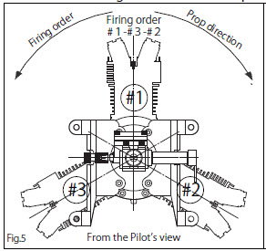
I say, ignore the rod and use the crank pin as the guide, lining it up with the cylinder bores center line for the cylinder you're currently timing.
A brief discussion: https://www.rcgroups.com/forums/show...odel-4-strokes
Last edited by Hobbsy; 06-11-2019 at 03:11 AM. Reason: Add picture
06-11-2019, 06:27 AM
#3
Thread Starter
Join Date: Apr 2010
Location: Altona, Victoria, AUSTRALIA
Posts: 82
Likes: 0
Received 0 Likes
on
0 Posts
Thanks Hobbsy,
i think that’s how the factory would have done it. I’ve actually used piston TDC for #2 and #3.
Maybe I’ve overthought it, but wouldn’t it be like doing a single cylinder engine and timing with 1 tooth off? I’ve run the engine and it has good idle and transition. My curiosity tells me to set it up as you say and compare the running between them.
i estimate about 6 degrees of rotation difference. Maybe, it just doesn’t matter with our toy engines!
06-11-2019, 07:35 AM
#4

Do you have a degree wheel? Pretty easy to find TDC with a piston stop on #1 and zero the degree wheel there. More accurate results gained by finding TDC on each cylinder using the same method as finding #1, but that may be splitting hairs.
The factory uses custom tooled fixtures most likely.
The factory uses custom tooled fixtures most likely.
 06-11-2019, 08:18 AM
#5
Thread Starter
Join Date: Apr 2010
Location: Altona, Victoria, AUSTRALIA
Posts: 82
Likes: 0
Received 0 Likes
on
0 Posts
Hi Jesse,
i have no trouble in finding top dead centre.
My question is TDC with piston fitted to the cylinder or TDC of the crank pin without piston fitted? ( there is a difference )
As Hobbsy said and other information I have seen is that the crank pin is used as a reference in determining TDC. But this does not give piston TDC on #2 and #3 when fitting the camshaft gear.
06-12-2019, 10:41 PM
#6
Thread Starter
Join Date: Apr 2010
Location: Altona, Victoria, AUSTRALIA
Posts: 82
Likes: 0
Received 0 Likes
on
0 Posts
Ok , for anyone that is following or interested, this is what I have discovered today.
Static rpms on glow are 8300 rpm
Today, I fitted a Morris mini motors timing ring and sensor to the engine. I already had one of Adrian’s 3 cylinder CDI units. I ran same prop and fuel and was only able to achieve 6500rpm! Hang on, all reports I’ve heard say even more rpms!
The timing is set at 32 BTDC. The engine ran smooth with good idle and transition. Cylinders #1 and #2 were cool compared to #3. There was no misses in the engine. Something is not quite right with this system so I took some timing measurements.
Obviously, the three cylinder engine has it’s cylinders spaced at 120 degrees to each other. The timing ring has the magnets spaced at 120 degrees......... all good so far.
I think if I go back to my original question I asked here it explains a lot.
I have found that TDC on cylinder #1 is say at 0 degrees, rotate the hub in direction of rotation then the next TDC should be at 120 degrees on #2 cylinder right! Wrong, it is at 126 degrees ( this has to do with the geometry of the slave rods in how they are connected to the master rod.)
I measured all cylinders and this is what the respective angles are to TDC
#1 to #2 is 126 degrees
#2 to #3 is 108 degrees
#3 to #1 is 126 degrees
None are at 120 degrees as per the timing magnets. I don’t know if the gas engines are the same but I assume they are.
What this means is that Cylinder #1 will fire at the time set correctly, say 30 degrees BTDC.
But cylinder #3 will fire 6 degrees late at 24 degrees BTDC.
And cylinder #2 will fire 6 degrees early at 36 degrees BTDC.
The only fix so that each cylinder gets to fire at the “ set time “ is if the magnets are spaced at 126-108-126 degrees to match the respective cylinder.
This obviously doesn’t affect a single cylinder glow to CDI, but certainly does with a multi Cylinder!
Has anyone had similar results to me in running glow on CDI?
Also, I would have thought both Adrian and Morris would have noticed this mistiming, sure it works but not very well!
look forward to some replies.
cheers Steve
#2 to #3 is 108 degrees
06-13-2019, 04:36 AM
#8
Thread Starter
Join Date: Apr 2010
Location: Altona, Victoria, AUSTRALIA
Posts: 82
Likes: 0
Received 0 Likes
on
0 Posts
Thanks Gary,
yes your right, but much better to have the timing of the ignition set correct and the same for all cylinders. I wonder if the gas radial engines are setup the same ?
Morris, from Morris mini engines has apparently come to the same realisation in England and is making alterations to his timing rings. He is sending me one with 126-108-126 magnet spacing.
06-13-2019, 05:04 AM
#9
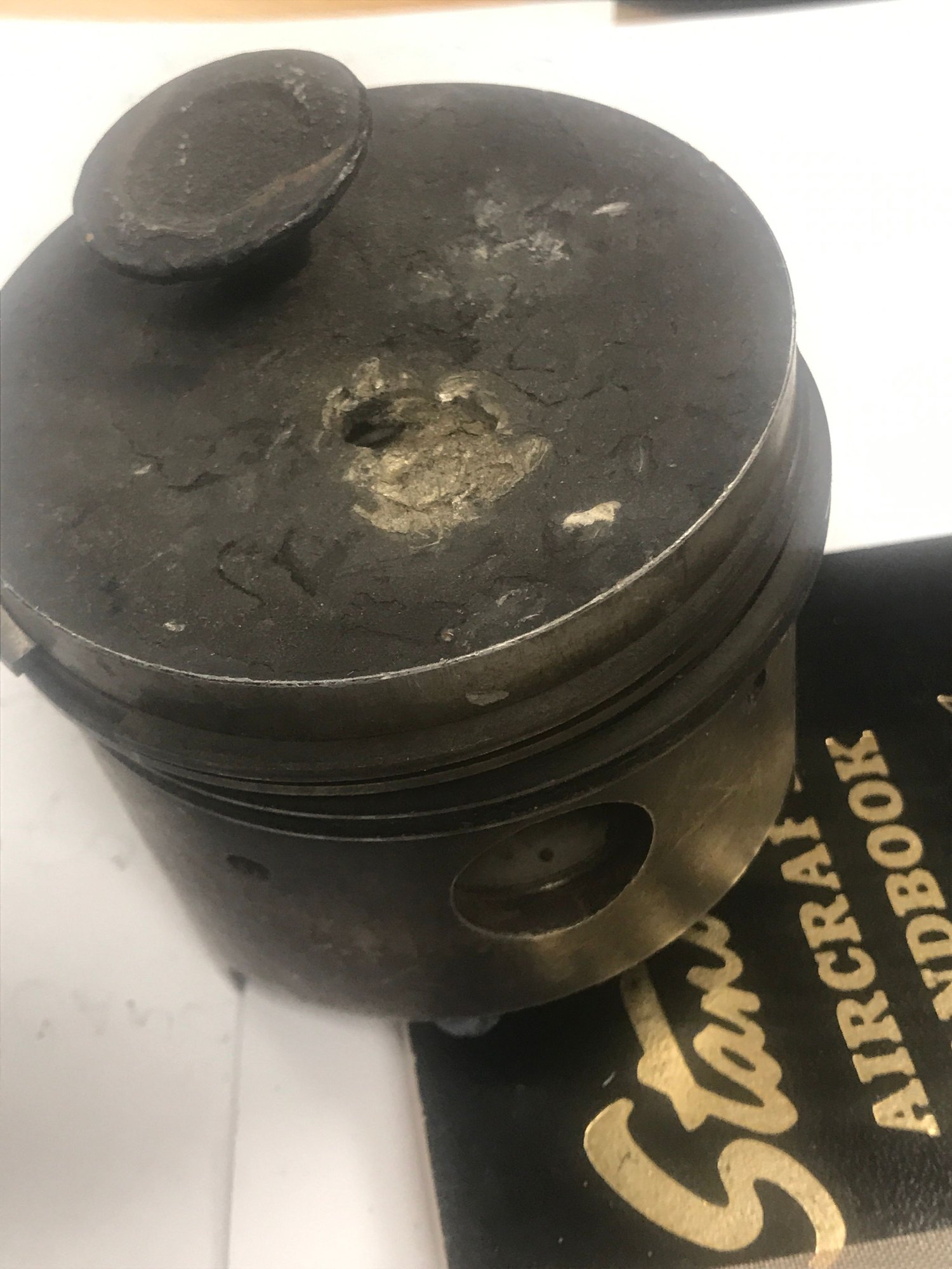
Retarded timing increases cylinder temperatures.
I used to have a box of VW Bug pistons that had swallowed valve heads. All came from #3 cylinders with retarded individual timing on the #3 cylinder.
I will look at the aviation engine handbook later for their take. I personally would lean towards piston position.
I used to have a box of VW Bug pistons that had swallowed valve heads. All came from #3 cylinders with retarded individual timing on the #3 cylinder.
I will look at the aviation engine handbook later for their take. I personally would lean towards piston position.
 06-13-2019, 10:33 AM
#11
Thread Starter
Join Date: Apr 2010
Location: Altona, Victoria, AUSTRALIA
Posts: 82
Likes: 0
Received 0 Likes
on
0 Posts
Some not so pretty pictures there! Once the timing ring is the correct spacing I will not have any retardation issue. I did note above that the #3 cylinder was hot compared to #1 and #2 though. #3 was retarded compared to those.
08-13-2023, 02:26 PM
#12

Ok , for anyone that is following or interested, this is what I have discovered today.
Static rpms on glow are 8300 rpm
Today, I fitted a Morris mini motors timing ring and sensor to the engine. I already had one of Adrian�s 3 cylinder CDI units. I ran same prop and fuel and was only able to achieve 6500rpm! Hang on, all reports I�ve heard say even more rpms!
The timing is set at 32 BTDC. The engine ran smooth with good idle and transition. Cylinders #1 and #2 were cool compared to #3. There was no misses in the engine. Something is not quite right with this system so I took some timing measurements.
Obviously, the three cylinder engine has it�s cylinders spaced at 120 degrees to each other. The timing ring has the magnets spaced at 120 degrees......... all good so far.
I think if I go back to my original question I asked here it explains a lot.
I have found that TDC on cylinder #1 is say at 0 degrees, rotate the hub in direction of rotation then the next TDC should be at 120 degrees on #2 cylinder right! Wrong, it is at 126 degrees ( this has to do with the geometry of the slave rods in how they are connected to the master rod.)
I measured all cylinders and this is what the respective angles are to TDC
#1 to #2 is 126 degrees
#2 to #3 is 108 degrees
#3 to #1 is 126 degrees
None are at 120 degrees as per the timing magnets. I don�t know if the gas engines are the same but I assume they are.
What this means is that Cylinder #1 will fire at the time set correctly, say 30 degrees BTDC.
But cylinder #3 will fire 6 degrees late at 24 degrees BTDC.
And cylinder #2 will fire 6 degrees early at 36 degrees BTDC.
The only fix so that each cylinder gets to fire at the � set time � is if the magnets are spaced at 126-108-126 degrees to match the respective cylinder.
This obviously doesn�t affect a single cylinder glow to CDI, but certainly does with a multi Cylinder!
Has anyone had similar results to me in running glow on CDI?
Also, I would have thought both Adrian and Morris would have noticed this mistiming, sure it works but not very well!
look forward to some replies.
cheers Steve
#2 to #3 is 108 degrees
