


Gilmore Red Lion Build


 05-19-2015, 05:06 PM
#353

Thread Starter

Join Date: Jul 2012
Location: Missouri
Posts: 1,127
Likes: 0
Received 0 Likes
on
0 Posts
I was going back and forth in my head on how to create an even ridge for the hub cap. Then it dawned on me. Just use fiberglass. DUH
So I wrapped the faces with shipping tape and then waxed the surface. Then wet out 8 layers of cloth. It may be too much but it was just a guess.
Will feather the edge if to thick.
As of now I intend to build up the infield of the glass discs with bondo. Then sand to a slight dome.
Once the shape is satisfactory the disc's will be glued to the plug.

Kevin
So I wrapped the faces with shipping tape and then waxed the surface. Then wet out 8 layers of cloth. It may be too much but it was just a guess.
Will feather the edge if to thick.
As of now I intend to build up the infield of the glass discs with bondo. Then sand to a slight dome.
Once the shape is satisfactory the disc's will be glued to the plug.
Kevin

 05-20-2015, 12:49 PM
#355
Thread Starter
Join Date: Jul 2012
Location: Missouri
Posts: 1,127
Likes: 0
Received 0 Likes
on
0 Posts
Robert,
Reproducing the shapes on this bird has been a Joy, Challenge,and Pain in the but. But has been very fulfilling.
Thank you for your appreciation my friend.
I cut the circles out of the layup. I got a little careless with the resin and starved an edge or two. Not to much of a problem since there is going to be putty party before it's done.
First thing was to mark the hubs before removing the glass from the plugs. I then drilled a center hole thru glass and mdf as an alignment. Then removed the glass and cut the circle. I got the edge I was looking for plus a little. Will probably end up tapering the edge a little. The challenging part will be at the base. On the reproduction pic on the previous page. At ground level the hub cap is a plate. I think I will make it a boot of sorts at this point so as to make it look like a plate but returning under to the wheel well.
This will require some sculpting. Hope all fairs well") . We will see.
. We will see.


Astute viewers will notice the index hole is off center low 1/4. The reason for this is a scale wheel comes out at 7 1/2 inches.
I could only find 7 and 8 inch wheels. So I opted for the 7 inch wheel. Lowering the axle 1/4 will keep the same clearance from ground to bottom of spat.
Kevin
Reproducing the shapes on this bird has been a Joy, Challenge,and Pain in the but. But has been very fulfilling.
Thank you for your appreciation my friend.
I cut the circles out of the layup. I got a little careless with the resin and starved an edge or two. Not to much of a problem since there is going to be putty party before it's done.
First thing was to mark the hubs before removing the glass from the plugs. I then drilled a center hole thru glass and mdf as an alignment. Then removed the glass and cut the circle. I got the edge I was looking for plus a little. Will probably end up tapering the edge a little. The challenging part will be at the base. On the reproduction pic on the previous page. At ground level the hub cap is a plate. I think I will make it a boot of sorts at this point so as to make it look like a plate but returning under to the wheel well.
This will require some sculpting. Hope all fairs well
. We will see. Astute viewers will notice the index hole is off center low 1/4. The reason for this is a scale wheel comes out at 7 1/2 inches.
I could only find 7 and 8 inch wheels. So I opted for the 7 inch wheel. Lowering the axle 1/4 will keep the same clearance from ground to bottom of spat.
Kevin
05-21-2015, 11:32 AM
#357
Thread Starter
Join Date: Jul 2012
Location: Missouri
Posts: 1,127
Likes: 0
Received 0 Likes
on
0 Posts
Mike.
You need a front , side, and top view.
I would cut the side profile first.
Then the top view profile.
Then make a template of the front profile.
Grinder down using that temp to check often you are not over sanding.
Once the top is sanded close (not over sanded) then make a sanding block same shape as template.
Sand that profile all the way back to tail taking care not to remove the center.
You want to sand down only to center. Holding sanding block square is critical.
Your arc will get shorter as you get to back. That's ok.
Next sand the bottom to whatever shape that is.
Then feather the top and bottom profiles toward each other while looking at pics.
Your front profile looks the same as the top shape. This is a bonus. Use same sanding block down around front.
I did this with my spat version 1. The problem with that is that my spat got thinner. But it got me real close
One other thing that was invaluable. Is to immobilize spat while doing violence to it.
The jig I made for my spats held them firm while working it over with both hands.
Two hands working is much better. I did my cowl plug one hand holding and one hand sanding.
That sucked. Will not do that again if can be helped.
That's how I arrived at what you see.
If you did that, then I am out of advise. Accept to "try harder".
Hope that helps.
Cool looking spat. You will get it.
Wax on, Wax off Danielson.
Kevin
Last edited by Melchizedek; 05-21-2015 at 12:24 PM.
05-21-2015, 05:36 PM
#359
Thread Starter
Join Date: Jul 2012
Location: Missouri
Posts: 1,127
Likes: 0
Received 0 Likes
on
0 Posts
Mike,
I really liked using the MDF for the plug material. It sands easy but not to easy (makes it harder to over sand).It virtually has no grain. It is rigid enough to engineer a mount through the wheel well.
And it is easy to make a centerline in it. Black magic marker around the center seam before glue up. And it's relatively cheep.
A belt sander and a surf form make rough shaping easy peasy. Just my 2 cents.
Kevin
05-21-2015, 05:48 PM
#360
Thread Starter
Join Date: Jul 2012
Location: Missouri
Posts: 1,127
Likes: 0
Received 0 Likes
on
0 Posts
I thought I should cut the wheel well pockets before I get much further. Right now without the hub caps the spats are symmetrical. Once the hub caps get attached the become semi symmetrical. A lot easier centering the wells now.
The same jig that was used to cut the mounting slots was used to cut the well perimeter. Just change the to template. The mounting box is the same.
I did not clear the infield of the wells cause I still need the mounting slots for working up the gear fairings.
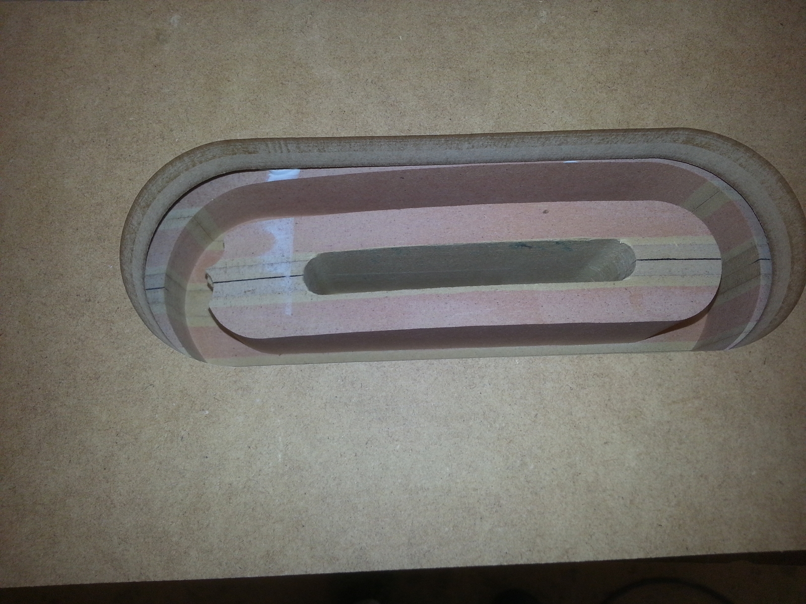


Kevin
The same jig that was used to cut the mounting slots was used to cut the well perimeter. Just change the to template. The mounting box is the same.
I did not clear the infield of the wells cause I still need the mounting slots for working up the gear fairings.
Kevin


 05-24-2015, 08:26 AM
#369
Thread Starter
Join Date: Jul 2012
Location: Missouri
Posts: 1,127
Likes: 0
Received 0 Likes
on
0 Posts
I ladled on the body filler on the infield of the hub caps. I wanted to make sure there was sufficient filler to do a full shape in on go.
Trouble was when the filler went off it generated enough heat to warp my hub caps. This turned a perfect fit into a crappy fit.

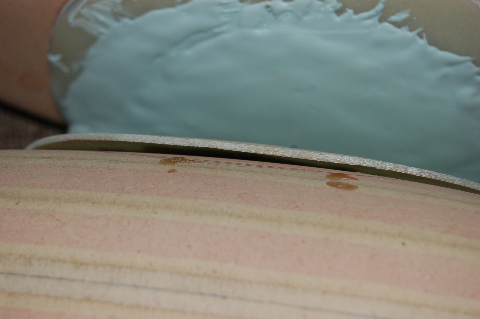
So to fix this, I removed some infield of mdf to bring the outer edges closer. I then covered each plug with packing tape and then smeared filler around the perimeter of each cap and pressed them into place. This gave me a tight rim again.


I then made a curved sanding block to contour the hub caps.

Once both caps were sanded to shape, I laid out and installed the fasteners .


I then made another parallel jig much like the sanding/painting jig.
Only this one holds the spats in there proper orientation with the ground with datum line level.
Every thing is set for center line. Since nothing is square of shape. Every thing will be worked off of level and center line.


Next will be to build a form to orient the gear fairings to the spats.
My spats became a hybrid combo of Hostetler's front and side profile/ Pete's spats top view, and the reproduction in Louisiana.
The reproduction is more bulbous around the axil and the wheel itself is more forward than Hostetler shows on his prints. So my hub caps don't look quite like the reproduction. But I am overall pretty happy with them.

Kevin
Trouble was when the filler went off it generated enough heat to warp my hub caps. This turned a perfect fit into a crappy fit.
So to fix this, I removed some infield of mdf to bring the outer edges closer. I then covered each plug with packing tape and then smeared filler around the perimeter of each cap and pressed them into place. This gave me a tight rim again.
I then made a curved sanding block to contour the hub caps.
Once both caps were sanded to shape, I laid out and installed the fasteners .
I then made another parallel jig much like the sanding/painting jig.
Only this one holds the spats in there proper orientation with the ground with datum line level.
Every thing is set for center line. Since nothing is square of shape. Every thing will be worked off of level and center line.
Next will be to build a form to orient the gear fairings to the spats.
My spats became a hybrid combo of Hostetler's front and side profile/ Pete's spats top view, and the reproduction in Louisiana.
The reproduction is more bulbous around the axil and the wheel itself is more forward than Hostetler shows on his prints. So my hub caps don't look quite like the reproduction. But I am overall pretty happy with them.
Kevin
Last edited by Melchizedek; 05-24-2015 at 08:33 AM.
05-24-2015, 05:58 PM
#370
Thread Starter
Join Date: Jul 2012
Location: Missouri
Posts: 1,127
Likes: 0
Received 0 Likes
on
0 Posts
Next step was to build a form to keep the gear fairing on plane.
The widest part of the fairing is 1 inch. So I glued to 1/2 mdf panels together to make the 1 inch.
Once the form was in place I laid a fairing blank in place (it is way over size at this point) and scribed a line to the pant.
I then beveled that edge to 33 degrees to get the back edge to touch the pant on profile. Covered each pant with packing tape then wax. I then mixed up some micro balloons and epoxy
paste to form fit the fairing to each pant.


Kevin
The widest part of the fairing is 1 inch. So I glued to 1/2 mdf panels together to make the 1 inch.
Once the form was in place I laid a fairing blank in place (it is way over size at this point) and scribed a line to the pant.
I then beveled that edge to 33 degrees to get the back edge to touch the pant on profile. Covered each pant with packing tape then wax. I then mixed up some micro balloons and epoxy
paste to form fit the fairing to each pant.
Kevin
Last edited by Melchizedek; 05-24-2015 at 06:04 PM.
05-25-2015, 09:30 AM
#371
Thread Starter
Join Date: Jul 2012
Location: Missouri
Posts: 1,127
Likes: 0
Received 0 Likes
on
0 Posts
Now that the fairings are fit to the pants it was time to size each fairing.
First thing I did was level up the drawing on wall to the datum line. Then shoot a cross beam line to find the stop start points of the fairing to the pant.
Then get the angle of each cant of fairing so that could be transferred to the blank.


Next was to shine the beams on the fairing as it sits on the jig. Since the fairing sits at an angle It is critical that the beam be dead on square to the side. Other wise the line would be would go askewed . So I set up the jig square to my table saw miter slot and adjusted the beam to shoot straight down the slot. This gave me true lines on the angled fairing.
The first pic is a long hand held exposure, that's why the line is so fat. Any way the front cant of the fairing is 3 1/2 degrees from datum and the trailing edge is 5 degrees.


I only laid out one side. Then pulled them off and matched the bottoms up and tacked them together. The lower part of the fairing gets attached to pant but needs to be shaped first. Never the less the joint needs established. So next was to cut both joints at the same time. A fence was nailed on the blank parallel to the cut and then cut on the table saw.
Then I biscuited each lower piece to its upper. Then used a router and straight edge to cut the leading and trailing edges. I then spot glued the lower and upper together so they can be shaped as one.


I now have the correct geometry of the fairing to the pants. Everything leans at the correct angle and is straight into the air stream.


Next on the list is to air foil the fairings.
Kevin
First thing I did was level up the drawing on wall to the datum line. Then shoot a cross beam line to find the stop start points of the fairing to the pant.
Then get the angle of each cant of fairing so that could be transferred to the blank.
Next was to shine the beams on the fairing as it sits on the jig. Since the fairing sits at an angle It is critical that the beam be dead on square to the side. Other wise the line would be would go askewed . So I set up the jig square to my table saw miter slot and adjusted the beam to shoot straight down the slot. This gave me true lines on the angled fairing.
The first pic is a long hand held exposure, that's why the line is so fat. Any way the front cant of the fairing is 3 1/2 degrees from datum and the trailing edge is 5 degrees.
I only laid out one side. Then pulled them off and matched the bottoms up and tacked them together. The lower part of the fairing gets attached to pant but needs to be shaped first. Never the less the joint needs established. So next was to cut both joints at the same time. A fence was nailed on the blank parallel to the cut and then cut on the table saw.
Then I biscuited each lower piece to its upper. Then used a router and straight edge to cut the leading and trailing edges. I then spot glued the lower and upper together so they can be shaped as one.
I now have the correct geometry of the fairing to the pants. Everything leans at the correct angle and is straight into the air stream.
Next on the list is to air foil the fairings.
Kevin