


Sig Spacewalker 1/3 scale (by rookie)
 04-09-2014, 01:25 PM
#126

Thread Starter

Join Date: Jul 2012
Location: Missouri
Posts: 1,127
Likes: 0
Received 0 Likes
on
0 Posts
Leroy,
Thanks for the kind words. Yes the power tools do come in handy especially on the bigger planes.
I've been working with power tools since I was 16.
The thought of using them on a model was foreign to me (accept for band, scroll and disc ) until about a year ago.
I saw Robert use a router to either make or true up some wing ribs on his first Pitts.
The thought was, ooh using the big guns on a model ? Then the light bulb went on.
Of course! Why not ? makes perfect sense!
Another hat tip to ya Robert.
Tom,
that one looks stout. Good to have friend with metal lathe.
I would love to have a metal lathe, next best thing is a friend with one.
Tony,
I did find some nylon ones from servo city. I had decided not to go with them cause they looked weak.
I did not see the metal coupler that you have though. Yours looks much stronger.
The pic below shows the connection point for the IRF on the left.
On the right is what I got from servo city. Looks suitable for maybe a park flyer, not any larger.

The IRF stuff I believe is strip proof. The coupler is female hexagonal to except the male hexagon on the output shaft.
The output shaft is hollow, the flipper arm is sweat into the end of hollow arm. The back of the nylon coupler is splined
to fit the servo gear. The flipper arms are of dead on equal length and bend angle and are hardened. If installed correctly, nothing to strip but the servo.
Hope that info is helpful to anyone considering RDS .
Kevin
Thanks for the kind words. Yes the power tools do come in handy especially on the bigger planes.
I've been working with power tools since I was 16.
The thought of using them on a model was foreign to me (accept for band, scroll and disc ) until about a year ago.
I saw Robert use a router to either make or true up some wing ribs on his first Pitts.
The thought was, ooh using the big guns on a model ? Then the light bulb went on.
Of course! Why not ? makes perfect sense!
Another hat tip to ya Robert.
Tom,
that one looks stout. Good to have friend with metal lathe.
I would love to have a metal lathe, next best thing is a friend with one.
Tony,
I did find some nylon ones from servo city. I had decided not to go with them cause they looked weak.
I did not see the metal coupler that you have though. Yours looks much stronger.
The pic below shows the connection point for the IRF on the left.
On the right is what I got from servo city. Looks suitable for maybe a park flyer, not any larger.
The IRF stuff I believe is strip proof. The coupler is female hexagonal to except the male hexagon on the output shaft.
The output shaft is hollow, the flipper arm is sweat into the end of hollow arm. The back of the nylon coupler is splined
to fit the servo gear. The flipper arms are of dead on equal length and bend angle and are hardened. If installed correctly, nothing to strip but the servo.
Hope that info is helpful to anyone considering RDS .
Kevin
 04-09-2014, 05:11 PM
#127


Join Date: Sep 2006
Location: The Sunshine state, when it's not raining!
Posts: 8,131
Likes: 0
Received 2 Likes
on
2 Posts
Glad to of been of some use. I also have used the IRF control's a couple of times and like them. They took a little bit of fidgeting to get perfect but after figuring them out it was simple.
And I use power tools as much as possible to ease the load of some aspects of building. I just loaned my router table to a friend to try rounding the wing, stab, ele, and rudder edges of a 1/3 scale Waco. Hope my tricks work out as well for him as they have for others.
And I use power tools as much as possible to ease the load of some aspects of building. I just loaned my router table to a friend to try rounding the wing, stab, ele, and rudder edges of a 1/3 scale Waco. Hope my tricks work out as well for him as they have for others.
04-12-2014, 06:15 PM
#128
Thread Starter
Join Date: Jul 2012
Location: Missouri
Posts: 1,127
Likes: 0
Received 0 Likes
on
0 Posts
Today worked on the aileron leading edge and wing trailing edge at aileron.
First cut the leading edge stock to length and glued it on.
I glued on this leading edge twice.
First time around everything looked good until I realized I forgot something.
I had not reamed the hinge block holes for the fat part of the robart hinge.
I never would have been able to seat the hinge far enough to get the hinge pin to the hinge line.
So I hurried and unclamped it . Luckily it let go without taking material with it.
Wiped all the glue off, reamed hinge blocks to proper depth and reglued.
This is the tool I used to widen the mouth of the hinge hole.
Never would have thought to do this if it wasn't for Vincent covering this detail on one of his builds.
Hat tip to Vince.

I used the piece I made for the machining of bullnose as a caul.
Before the RO was glued on I laid out center marks for hinge point holes and L R of RDS pocket.


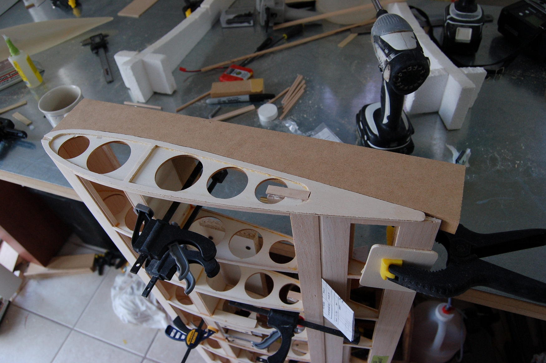
Next attention was paid to the aileron socket.
I made a little jig to cut the arc's in the rib ends.
Cut a piece of oak with the correct radius on one end with the other end touching the main spar.
The main spar indexed the arc cut, that way they would all be the same.
If you look close in the next pic you will see the piece of oak on my original layout line on the rib.
The other end of that piece of oak is resting on the main wing spar.
I used porcupine on a stick to make this cut. It made short work of the wing ribs.
This cut is just a little proud of finished dimension. The ends will get sanded to dimension but they are real close hear.


Next I sanded the ailerons leading edge to final shape.
Then sanded the trailing edge socket to final shape.


Till next time.
Kevin
First cut the leading edge stock to length and glued it on.
I glued on this leading edge twice.
First time around everything looked good until I realized I forgot something.
I had not reamed the hinge block holes for the fat part of the robart hinge.
I never would have been able to seat the hinge far enough to get the hinge pin to the hinge line.
So I hurried and unclamped it . Luckily it let go without taking material with it.
Wiped all the glue off, reamed hinge blocks to proper depth and reglued.
This is the tool I used to widen the mouth of the hinge hole.
Never would have thought to do this if it wasn't for Vincent covering this detail on one of his builds.
Hat tip to Vince.
I used the piece I made for the machining of bullnose as a caul.
Before the RO was glued on I laid out center marks for hinge point holes and L R of RDS pocket.
Next attention was paid to the aileron socket.
I made a little jig to cut the arc's in the rib ends.
Cut a piece of oak with the correct radius on one end with the other end touching the main spar.
The main spar indexed the arc cut, that way they would all be the same.
If you look close in the next pic you will see the piece of oak on my original layout line on the rib.
The other end of that piece of oak is resting on the main wing spar.
I used porcupine on a stick to make this cut. It made short work of the wing ribs.
This cut is just a little proud of finished dimension. The ends will get sanded to dimension but they are real close hear.
Next I sanded the ailerons leading edge to final shape.
Then sanded the trailing edge socket to final shape.
Till next time.
Kevin
04-13-2014, 03:17 AM
#129
It's coming out super Kevin! Don't you just love it when the fruits of your labor yield such nice work....but be forewarned, at this rate, when completed you just may have a very unique one-off type of SW just like Leroy!
BTW, what are the metal blocks with all the holes in them used for?
BTW, what are the metal blocks with all the holes in them used for?
Last edited by VincentJ; 04-13-2014 at 03:22 AM.
04-13-2014, 04:47 AM
#130
Thread Starter
Join Date: Jul 2012
Location: Missouri
Posts: 1,127
Likes: 0
Received 0 Likes
on
0 Posts
Vince,
Those are 1 2 3 machine blocks. I believe they are used for setups in machine work.
They are square, flat and parallel. 1" by 2" by 3" . Some of the holes are threaded.
Machined hardened steal so they have a little weight to them too.
They come in real handy, set two together and what is between is dead on square.
With a magnetic table they can be locked in place with a few magnets.
Your imagination is there only limit. I wish I had 20 of them.
They come shellacked in oil. I soaked mine in lacquer thinner to clean them up.
http://www.littlemachineshop.com/pro...1233&category=
oh, and thanks Vincent, there was a shadow of a doubt this might not go well.
When everything is hinged and functions well all shadows will fade away and grins can commence.
All ahead full
Kevin
Last edited by Melchizedek; 04-13-2014 at 08:38 AM.
04-13-2014, 12:44 PM
#131
Thread Starter
Join Date: Jul 2012
Location: Missouri
Posts: 1,127
Likes: 0
Received 0 Likes
on
0 Posts
The trailing edge got some more TLC.
I cut some 3/32 balsa sheer webs and closed in the aileron bays.
This really stiffened up the trailing edge. Something like this was suggested by Leroy.
Hat tip Leroy


Next up decided to drill the preliminary holes for the hinges in the aileron leading edge.
To drill straight thru the center I set a fence up at 9 deg on the drill press.


I was just a little hit and miss on these holes but they will get elongated for aileron deflection.
I put the dowel pins in I used to set the hinge blocks and then set the aileron in the wing.


By Jove I think it might work. Getting very close to possible grins .
The manual says "recommended aileron movement is 1-1/6 up and 15/16 down."
The throw will determine the extent the hinge point holes get elongated.
Does anybody have an opinion on what I should set maximum throw on the ailerons ?
Thanks,
Kevin
I cut some 3/32 balsa sheer webs and closed in the aileron bays.
This really stiffened up the trailing edge. Something like this was suggested by Leroy.
Hat tip Leroy
Next up decided to drill the preliminary holes for the hinges in the aileron leading edge.
To drill straight thru the center I set a fence up at 9 deg on the drill press.
I was just a little hit and miss on these holes but they will get elongated for aileron deflection.
I put the dowel pins in I used to set the hinge blocks and then set the aileron in the wing.
By Jove I think it might work. Getting very close to possible grins .
The manual says "recommended aileron movement is 1-1/6 up and 15/16 down."
The throw will determine the extent the hinge point holes get elongated.
Does anybody have an opinion on what I should set maximum throw on the ailerons ?
Thanks,
Kevin
04-13-2014, 09:46 PM
#132
It's coming out super Kevin! Don't you just love it when the fruits of your labor yield such nice work....but be forewarned, at this rate, when completed you just may have a very unique one-off type of SW just like Leroy!
BTW, what are the metal blocks with all the holes in them used for?
BTW, what are the metal blocks with all the holes in them used for?
Leroy
04-13-2014, 10:02 PM
#133
Kevin it's looking real good, take note of the size of the control surfaceses, they are not small and have alot of cord that will deflect alot more than narrow ones, a 1/4" more is alot given there size, thats just my opinion. Your doing great, gonna be a nice plane for sure.
Leroy
Leroy
04-14-2014, 02:13 PM
#134
Thread Starter
Join Date: Jul 2012
Location: Missouri
Posts: 1,127
Likes: 0
Received 0 Likes
on
0 Posts
Thanks for your input Leroy,
I had not taken into account the size of surface just the demission of deflection. (forest trees thingy)
What you say makes since to me. I think I will add the 1/4 just for head room for ' you never know.'
If I can keep the hinge slots within the realm of the aileron pocket ie out of sight.
Kevin
I had not taken into account the size of surface just the demission of deflection. (forest trees thingy)
What you say makes since to me. I think I will add the 1/4 just for head room for ' you never know.'
If I can keep the hinge slots within the realm of the aileron pocket ie out of sight.
Kevin
04-19-2014, 02:45 PM
#135
Thread Starter
Join Date: Jul 2012
Location: Missouri
Posts: 1,127
Likes: 0
Received 0 Likes
on
0 Posts
This week attention was paid to the aileron servo bays.
The servo needs to be adjustable for and aft.
The reason for this is the dog leg in the flipper arm.
To far into pocket it binds to far out of pocket and it binds.
So I decided to make some use of 1/16 wall aluminum angle.
The blocks the servo is screwed to will slide for and aft on the angle.
I used little shim blocks under the angle to get the correct angle and depth.
After scuffing up the sides they were epoxied in place.


Next a bass wood bridge was epoxied to angels and spar.


Next moon shaped ply fillers were epoxied to the angel sides and scabs over that.


Then hinge points were modified.
Leroy, I made and attempt to rib the brass as you described.
I think my tube cutter wheel was to sharp. By the time I had a rib it was scored to deep.
I made several attempts. The score lines were to deep for my comfort zone.
So what I did was cut brass tubing to length and then rough up the inside with an abrasive dremel bit.


I then washed the hinges with denatured alcohol.
The brass is slightly shorter than 2 hinge legs.
So I cut a donor leg short to make a plug. The plug was to prevent epoxy from being pushed out the other end.
Placed liberal amount of epoxy in open end and slowly pressed hinge in cause glue to squeeze out front and around hinge barbs.
I wiped epoxy as I went. Once hinge was seated I carefully twisted donor leg out.
I then took a nail set and put indents between barbs on opposite sides of brass.


I then enlarged the hinge blocks at wing trailing edge to accept brass leg.

And then my honey said it's time to go get and ice cream ! ok
Kevin
The servo needs to be adjustable for and aft.
The reason for this is the dog leg in the flipper arm.
To far into pocket it binds to far out of pocket and it binds.
So I decided to make some use of 1/16 wall aluminum angle.
The blocks the servo is screwed to will slide for and aft on the angle.
I used little shim blocks under the angle to get the correct angle and depth.
After scuffing up the sides they were epoxied in place.
Next a bass wood bridge was epoxied to angels and spar.
Next moon shaped ply fillers were epoxied to the angel sides and scabs over that.
Then hinge points were modified.
Leroy, I made and attempt to rib the brass as you described.
I think my tube cutter wheel was to sharp. By the time I had a rib it was scored to deep.
I made several attempts. The score lines were to deep for my comfort zone.
So what I did was cut brass tubing to length and then rough up the inside with an abrasive dremel bit.
I then washed the hinges with denatured alcohol.
The brass is slightly shorter than 2 hinge legs.
So I cut a donor leg short to make a plug. The plug was to prevent epoxy from being pushed out the other end.
Placed liberal amount of epoxy in open end and slowly pressed hinge in cause glue to squeeze out front and around hinge barbs.
I wiped epoxy as I went. Once hinge was seated I carefully twisted donor leg out.
I then took a nail set and put indents between barbs on opposite sides of brass.
I then enlarged the hinge blocks at wing trailing edge to accept brass leg.
And then my honey said it's time to go get and ice cream !
okKevin
 04-19-2014, 05:57 PM
#137
Kevin those hinges will be solid as a rock, another thing to do because there are no ribs now is drill a series of 1/16" holes in a couple sides, they will grab on to the epoxy and never pull out.. In the future you can use a diamond hone to take the edge off a cutter and set it aside for future use. I have noticed your a pretty good problem solver also, the more you learn the more cerative you will get, your developing a very good building style and it shows, I think you had it all along.
Leroy.
Leroy.
04-20-2014, 08:57 AM
#139
Thread Starter
Join Date: Jul 2012
Location: Missouri
Posts: 1,127
Likes: 0
Received 0 Likes
on
0 Posts
Thanks Leroy for the encouraging and thoughtful words.
Keeps one motivated, it does.
And thank you Robert, I hope your students placed well in there competition.
Have a safe journey back.
Anxious to see your paint scheme for your Edge.
Kevin
Keeps one motivated, it does.
And thank you Robert, I hope your students placed well in there competition.
Have a safe journey back.
Anxious to see your paint scheme for your Edge.
Kevin
04-20-2014, 01:04 PM
#141
Thread Starter
Join Date: Jul 2012
Location: Missouri
Posts: 1,127
Likes: 0
Received 0 Likes
on
0 Posts
Woops, do I feel sheepish 
Attribute it to my ADHD and other maladies.
HONEY BRING ME MY MEDS !!!!!!!!!
Seriously I'm guilty of pondering to many things at once.
Sorry Vincent.
Kevin
Attribute it to my ADHD and other maladies.
HONEY BRING ME MY MEDS !!!!!!!!!
Seriously I'm guilty of pondering to many things at once.
Sorry Vincent.
Kevin
04-26-2014, 10:38 AM
#144
Thread Starter
Join Date: Jul 2012
Location: Missouri
Posts: 1,127
Likes: 0
Received 0 Likes
on
0 Posts
Fastening plates for the servo mounts were made.
They have a keeper strip to keep the blind nuts from turning.
This enables the servo to slide for and aft for fine tuning.
The wood blocks the servos are screwed to will get trimmed down a little.


Finally got the ailerons functional.
Now I can turn my attention to the rest of the build. YAAAAAAY !!!!!!!!!!!!!!!
The video below shows there function.
Encase you were wondering, the hinges are NOT glued in.")
The wings are upside down , the servo access covers are yet to be installed.
http://youtu.be/R9My4DruKBM
Kevin
They have a keeper strip to keep the blind nuts from turning.
This enables the servo to slide for and aft for fine tuning.
The wood blocks the servos are screwed to will get trimmed down a little.
Finally got the ailerons functional.
Now I can turn my attention to the rest of the build. YAAAAAAY !!!!!!!!!!!!!!!
The video below shows there function.
Encase you were wondering, the hinges are NOT glued in.
The wings are upside down , the servo access covers are yet to be installed.
http://youtu.be/R9My4DruKBM
Kevin
Last edited by Melchizedek; 04-26-2014 at 11:03 AM.
04-26-2014, 06:18 PM
#145
Thread Starter
Join Date: Jul 2012
Location: Missouri
Posts: 1,127
Likes: 0
Received 0 Likes
on
0 Posts
Next up was to fit and glue the servo bay cover.
The ply was a little warped and bowed. So I added 1/4 x 3/8 balsa underneath to hold ply straight and stiffen it.
Cover plates still have to be fit and sanded to airfoil.


Next up was to sand the outer ends of both wings flush with last rib.
Then glue WTR rib to the outside. The fiberglass wing tip will lap this plate and sit flush with wing skin.
At least that is the plan. Some work will need to be done to WTR cause it is a little bigger than wing skin.
The plan is after the WTR is glued on to rabbit that plate around the perimeter of airfoil the thickness of wing tip.
I will use Bees Knees for this. (Tony )
)


Till next time,
Kevin
The ply was a little warped and bowed. So I added 1/4 x 3/8 balsa underneath to hold ply straight and stiffen it.
Cover plates still have to be fit and sanded to airfoil.
Next up was to sand the outer ends of both wings flush with last rib.
Then glue WTR rib to the outside. The fiberglass wing tip will lap this plate and sit flush with wing skin.
At least that is the plan. Some work will need to be done to WTR cause it is a little bigger than wing skin.
The plan is after the WTR is glued on to rabbit that plate around the perimeter of airfoil the thickness of wing tip.
I will use Bees Knees for this. (Tony
)Till next time,
Kevin
Last edited by Melchizedek; 04-26-2014 at 06:20 PM.
04-27-2014, 09:04 AM
#146
Thread Starter
Join Date: Jul 2012
Location: Missouri
Posts: 1,127
Likes: 0
Received 0 Likes
on
0 Posts
If you have not built this plane I just want to say I am proceeding a little out of sequence from Kit instructions.
Not to much, and not in anyway getting to far ahead for trouble, at least to my limited knowledge.
Going with what animates me at the moment.
WTR is dry and it is time to dress it down.
I locked the aileron into its neutral position and spot glued the very end of WTR to aileron tip locking all in place.
I then prepared Mr. Bees Knees to cut WTR to dimension.
Mr. Knees has M4 treads in base plate. So I utilized them for a fence.
Set bit depth thickness of WTR ply and fence depth thickness of FG wing tip.


I then needed to set up a platform for MR. Knees to stay square to wing tip end.
Not so much on thick part of wing but on the skinny trailing edge part.
I did a platform for each side of airfoil.

Then ran Mr. Knees around wing tip end.


I was excited to set the wing tip on wing end. Then disappointment set in.
I am not happy with the FG wing tips. First they are a little large.
From the leading edge to the beginning of the aileron this can be pulled tight to wing.
But at the aileron there is to much to pull tight.
The other thing is they are strong at the radius edges (naturally) but are terribly flimsy at the flatter top and bottom.
So much so it is way to easy to push big dents in (they do pop out) but to soft for my comfort zone.
Also one of the tips has a big dent molded in.
As for the trailing edge of wing tip I will split it with the band saw to bring it together and bondo the trailing edge tip to shape.
Too much trailing edge Molded in dent
  .
.
So what I decided to do is to strengthen flatter areas and try and get dent out.
Then split trailing edge and bring it together.
I had some heavy CF remnants from a bicycle I built a few years back.I think it is in ballpark of 6 oz.
Wiped wt out with denatured alcohol then roughed them up with 80 grit.
The dent is on the bottom so I clamped a flat block over dent to hold it out to rest of wing tip.
There is a plastic sheet between wet cf and blocks.
The one on the right is the dented one. I clamped a block to the other so both tips have the same shape in the end (good or bad)
When this is dry I will place a layer on the top inside of wing tips to strengthen that plane.

Is it common for the Fiberglass parts not to fit to well ?
Kevin
Not to much, and not in anyway getting to far ahead for trouble, at least to my limited knowledge.
Going with what animates me at the moment.
WTR is dry and it is time to dress it down.
I locked the aileron into its neutral position and spot glued the very end of WTR to aileron tip locking all in place.
I then prepared Mr. Bees Knees to cut WTR to dimension.
Mr. Knees has M4 treads in base plate. So I utilized them for a fence.
Set bit depth thickness of WTR ply and fence depth thickness of FG wing tip.
I then needed to set up a platform for MR. Knees to stay square to wing tip end.
Not so much on thick part of wing but on the skinny trailing edge part.
I did a platform for each side of airfoil.
Then ran Mr. Knees around wing tip end.
I was excited to set the wing tip on wing end. Then disappointment set in.
I am not happy with the FG wing tips. First they are a little large.
From the leading edge to the beginning of the aileron this can be pulled tight to wing.
But at the aileron there is to much to pull tight.
The other thing is they are strong at the radius edges (naturally) but are terribly flimsy at the flatter top and bottom.
So much so it is way to easy to push big dents in (they do pop out) but to soft for my comfort zone.
Also one of the tips has a big dent molded in.
As for the trailing edge of wing tip I will split it with the band saw to bring it together and bondo the trailing edge tip to shape.
Too much trailing edge
So what I decided to do is to strengthen flatter areas and try and get dent out.
Then split trailing edge and bring it together.
I had some heavy CF remnants from a bicycle I built a few years back.I think it is in ballpark of 6 oz.
Wiped wt out with denatured alcohol then roughed them up with 80 grit.
The dent is on the bottom so I clamped a flat block over dent to hold it out to rest of wing tip.
There is a plastic sheet between wet cf and blocks.
The one on the right is the dented one. I clamped a block to the other so both tips have the same shape in the end (good or bad)
When this is dry I will place a layer on the top inside of wing tips to strengthen that plane.
Is it common for the Fiberglass parts not to fit to well ?
Kevin
04-27-2014, 04:56 PM
#147
Thread Starter
Join Date: Jul 2012
Location: Missouri
Posts: 1,127
Likes: 0
Received 0 Likes
on
0 Posts
Decided to dress up the fit at wing joints next before gluing the two wing center sections together.
First thing was to glue 1/8 x 3/8 ply brace at the 4 wing ribs that join at the wing joint.
When that was dry I sanded the wing joint flat on the small center sections.
I then placed a piece of 3/8 glass on the bench and ironed some monocot to it and waxed it up.
Then mixed up some epoxy and micro balloons.


Next will be addressing other side of wing joint.
Kevin
First thing was to glue 1/8 x 3/8 ply brace at the 4 wing ribs that join at the wing joint.
When that was dry I sanded the wing joint flat on the small center sections.
I then placed a piece of 3/8 glass on the bench and ironed some monocot to it and waxed it up.
Then mixed up some epoxy and micro balloons.
Next will be addressing other side of wing joint.
Kevin
04-27-2014, 05:04 PM
#148
Join Date: Sep 2006
Location: The Sunshine state, when it's not raining!
Posts: 8,131
Likes: 0
Received 2 Likes
on
2 Posts
Dude! Some of us are starting to really, really, REALLY, take issue with the term ROOKIE in the thread title.
Your making some of us look really bad with such outstanding craftsmanship at a supposedly rookie state.
Your making some of us look really bad with such outstanding craftsmanship at a supposedly rookie state.
04-27-2014, 06:22 PM
#149
Thread Starter
Join Date: Jul 2012
Location: Missouri
Posts: 1,127
Likes: 0
Received 0 Likes
on
0 Posts
Thank you Robert.
Full disclosure :
I have been a cabinet maker at a commercial custom cabinet shop for 30 years.
Working with wood, veneers, plastic lam, plastic, solid surfaces (corian, avonite, others), aluminum, steel and other stuff.
Started before CNC equipment so I crawled on the floor and laid out radius fixtures like reception desks and conference tables.
Then built fixtures off of layout kind of like our building off prints.
Now we have CNC so I don't have to crawl on floor too much any more but sometimes I do.
Many of the skills above are directly transferable to making airplanes.
Funny, making airplanes (Guillows rubber band) as a kid got me into cabinetmaking.
As a kid I would have loved to do what I am doing now but did not have funds or mentor to get here.
I read RC modeler as a youth and dreamed but it stayed a dream.
So that brings me to today.
My neighbor got into RC about a year before me. He's responsible.
2 years ago I began devouring build thread from first RCSB and then here.
Last winter built my Kadet and continued reading build threads.
Last summer I learned how to fly the Kadet.
My nature is to research the hell out of something then try to do it right.
I love to learn about things that animate me.
So where does Rookie come in ?
Flying.
I am not ready to advance from my Kadet. It still is a handful for me.
Building light. My nature is to make sure it don't break.
Batteries and electricity, this stuff is Greek to me.
Engines , electric and plumbing.
Basically I am new to the hobby.
This would be my second year in.
Still flying a trainer.
Very much to learn.
That's why the Rookie.
Also Rookie cause some of the builds I have followed here and on RCSB the last year and a half.
I could not see myself as anything other than a Rookie.
Besides, Rookie doesn't mean unable, it just means new guy to the sport, hobby or trade.
Ability yes, wisdom and experience not so much.
That's why I follow the veterans like you Robert.
So much to learn !
Kevin