Go Back  RCU Forums > RC Airplanes > Kit Building
Reload this Page >

G&L 1/5 DHC chipmunk - diary of a build.

Community
Search
Notices
Kit Building If you're building a kit and have questions or want to discuss kit building post it here.

G&L 1/5 DHC chipmunk - diary of a build.

Thread Tools
 
Search this Thread
 
Old 07-19-2014, 12:44 PM
  #351  
TonyBuilder
Thread Starter
My Feedback: (11)
 
TonyBuilder's Avatar
 
Join Date: Mar 2010
Location: Austin , TX
Posts: 4,166
Likes: 0
Received 1 Like on 1 Post
Default

Main gear set.

Went flying this morning to get some more fuel threw the DLE55, got about 3.5 hr and two gal threw her so far. This engine runs great and has been flawless for 20 flights.

I have been working on the main gear. I cut the struts down and removed the wood dowel so my struts are not to stiff.
I like it when the plane is sitting on its wheels and I can grab a wing tip and rock the plane back and forth. The shock absorption should not be so stiff that the struts won't compress unless it is hit hard.

Landings on this plane will be soft, plus I will be flying off grass and asphalt.


The strut fairing is light and strong, even better it is removable. The top and bottom are faced with 1/8" micro-ply


The two tabs at the bottom of the strut will hold the faring inline, so no need for any screws and fasteners.


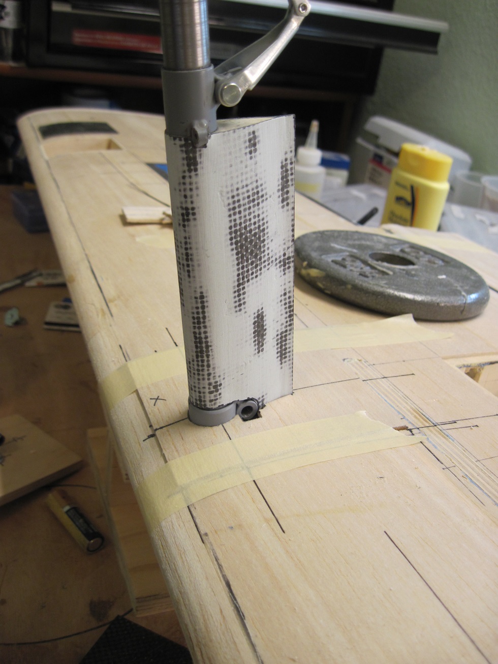
For setting up my gear I have a method that has worked good for me. I use this on both fixed and retractable gear.
First I level the wing from LE to TE. Then I use a steel rod the diameter of my axles to align the axles. In this case a 1/4" steel dowel from HD.
When I set up my gear I do not want toe in and anything like that, dead on is the way I roll

using a square I set the axles off the LE, I want them centered over the LE for this plane (and most tail draggers).


This is how I set the gear so I can mark the blocks. I will be gluing them in, that will be the next steep. Then I will install the covers and trim the fairings to fit.


TB
Attached Thumbnails Click image for larger version

Name:	main gear set 001.JPG
Views:	173
Size:	305.6 KB
ID:	2015615   Click image for larger version

Name:	main gear set 005.JPG
Views:	177
Size:	200.4 KB
ID:	2015616   Click image for larger version

Name:	main gear set 006.JPG
Views:	184
Size:	261.4 KB
ID:	2015617   Click image for larger version

Name:	main gear set 007.JPG
Views:	167
Size:	216.2 KB
ID:	2015618   Click image for larger version

Name:	main gear set 008.JPG
Views:	175
Size:	1.26 MB
ID:	2015619   Click image for larger version

Name:	main gear set 009.JPG
Views:	163
Size:	309.5 KB
ID:	2015620   Click image for larger version

Name:	main gear set 010.JPG
Views:	154
Size:	307.1 KB
ID:	2015621   Click image for larger version

Name:	main gear set 011.JPG
Views:	179
Size:	371.8 KB
ID:	2015622  

Click image for larger version

Name:	main gear set 012.JPG
Views:	177
Size:	247.3 KB
ID:	2015623   Click image for larger version

Name:	main gear set 013.JPG
Views:	168
Size:	288.5 KB
ID:	2015624   Click image for larger version

Name:	main gear set 014.JPG
Views:	164
Size:	290.1 KB
ID:	2015625   Click image for larger version

Name:	main gear set 015.JPG
Views:	174
Size:	348.3 KB
ID:	2015626   Click image for larger version

Name:	main gear set 016.JPG
Views:	164
Size:	369.9 KB
ID:	2015627   Click image for larger version

Name:	main gear set 017.JPG
Views:	163
Size:	368.5 KB
ID:	2015628   Click image for larger version

Name:	main gear set 018.JPG
Views:	156
Size:	374.1 KB
ID:	2015629   Click image for larger version

Name:	main gear set 019.JPG
Views:	170
Size:	201.9 KB
ID:	2015630  

Click image for larger version

Name:	main gear set 020.JPG
Views:	177
Size:	265.1 KB
ID:	2015631  

Last edited by TonyBuilder; 07-19-2014 at 12:47 PM.
Old 07-19-2014, 01:03 PM
  #352  
Zor
Banned
 
Join Date: Feb 2009
Location: Ontario, ON, CANADA
Posts: 3,524
Likes: 0
Received 1 Like on 1 Post
Default Just thinking

Tony,

Thanks for the fix. I have nice pics as always.

F Y I _ _ _ You may already know this _ _ _
The original propellers were designed by Dehavilland and made of wood.
Later some metal props were used.

The original props had a diameter of 2m ( 78.84 inches ). Scaling 1/5 would be 15.77 inches.
You may think of using a 16" prop with wide blades considering the engine you are using.

This would allow a scale dimensioned landing gear and a normal ground attitude of approximately 12 degrees as the full size thus giving a 14 degrees angle of attack ( just below full stall ) on a three point landing .

Just doing some thinking _ _ _ please do not mind me.

Zor

Last edited by Zor; 07-19-2014 at 01:48 PM. Reason: Corrected landng to landing
Old 07-19-2014, 01:25 PM
  #353  
TonyBuilder
Thread Starter
My Feedback: (11)
 
TonyBuilder's Avatar
 
Join Date: Mar 2010
Location: Austin , TX
Posts: 4,166
Likes: 0
Received 1 Like on 1 Post
Default

Zor your "thinking" is always welcome!

Im not going all out scale (sports scale) so my gear right now is 7" and my prop is a 22x10. My first build had plenty of clearance.


TB
Old 07-19-2014, 04:21 PM
  #354  
RCKen
RCU Forum Manager/Admin
My Feedback: (9)
 
RCKen's Avatar
 
Join Date: Jul 2002
Location: Lawton, OK
Posts: 27,767
Likes: 0
Received 27 Likes on 24 Posts
Default

Originally Posted by TonyBuilder
RCU has been really difficult lately, very hard to post or do anything, been getting worse. I gave up this morning after messing with it for way to long, took me but a min to post the same on RCG!

TB
I apologize for the problems you are having with pictures. The tech team is working on our image servers as they are getting ready to move to some new servers that should upgrade out performance. Hopefully the technical difficulties will be gone soon and we will be left with better service. And once again, I apologize for the problems.

Ken
Old 07-19-2014, 05:20 PM
  #355  
TonyBuilder
Thread Starter
My Feedback: (11)
 
TonyBuilder's Avatar
 
Join Date: Mar 2010
Location: Austin , TX
Posts: 4,166
Likes: 0
Received 1 Like on 1 Post
Default

Thanks Ken, I was thinking it was just me!

TB
Old 07-20-2014, 03:00 AM
  #356  
TonyBuilder
Thread Starter
My Feedback: (11)
 
TonyBuilder's Avatar
 
Join Date: Mar 2010
Location: Austin , TX
Posts: 4,166
Likes: 0
Received 1 Like on 1 Post
Default

I am making templates of the gear bay covers out of 3/32" balsa before I cut the hatches. I am plugging away on the gear and strut fairings.


On the bench for today will be to finish the gear installation, fairings and hatch covers, but first some flying


TB
Attached Thumbnails Click image for larger version

Name:	gear cover 001.JPG
Views:	152
Size:	317.5 KB
ID:	2015707   Click image for larger version

Name:	gear cover 002.JPG
Views:	176
Size:	310.8 KB
ID:	2015708   Click image for larger version

Name:	gear cover 003.JPG
Views:	183
Size:	252.9 KB
ID:	2015709  
Old 07-21-2014, 04:09 AM
  #357  
TonyBuilder
Thread Starter
My Feedback: (11)
 
TonyBuilder's Avatar
 
Join Date: Mar 2010
Location: Austin , TX
Posts: 4,166
Likes: 0
Received 1 Like on 1 Post
Default

Main gear mounts.

I am gluing the gear mounts in, the rails where set yesterday and I glassed the ceiling of the gear bays with some scrap carbon fiber.


I used 6/32 T-bolts for the gear mount plats, they wont pull out like screws will.


Gear mounting plates are glued in and drying.


I have started working on the landing light. I keep all scraps from layups, they come in handy at times.


TB
Attached Thumbnails Click image for larger version

Name:	main gear blocks 001.JPG
Views:	173
Size:	474.9 KB
ID:	2015918   Click image for larger version

Name:	main gear blocks 002.JPG
Views:	172
Size:	312.4 KB
ID:	2015919   Click image for larger version

Name:	main gear blocks 003.JPG
Views:	145
Size:	311.0 KB
ID:	2015920   Click image for larger version

Name:	main gear blocks 004.JPG
Views:	156
Size:	350.3 KB
ID:	2015921   Click image for larger version

Name:	main gear blocks 005.JPG
Views:	150
Size:	400.0 KB
ID:	2015922   Click image for larger version

Name:	main gear blocks 006.JPG
Views:	153
Size:	310.6 KB
ID:	2015923   Click image for larger version

Name:	main gear blocks 007.JPG
Views:	213
Size:	293.1 KB
ID:	2015924   Click image for larger version

Name:	main gear blocks 008.JPG
Views:	158
Size:	436.7 KB
ID:	2015925  

Old 07-21-2014, 08:27 AM
  #358  
TonyBuilder
Thread Starter
My Feedback: (11)
 
TonyBuilder's Avatar
 
Join Date: Mar 2010
Location: Austin , TX
Posts: 4,166
Likes: 0
Received 1 Like on 1 Post
Default

Gear hatch cover.

I got both gear hatch covers cut and installed.


The hatches will be held with 1/4" magnets, a metal plate was glued to the back of the hatch for the magnets.


Strut fairings are cut to length and sit right on top of the hatch.


TB
Attached Thumbnails Click image for larger version

Name:	landing light 001.JPG
Views:	145
Size:	313.8 KB
ID:	2015995   Click image for larger version

Name:	landing light 002.JPG
Views:	158
Size:	321.8 KB
ID:	2015996   Click image for larger version

Name:	landing light 003.JPG
Views:	135
Size:	496.5 KB
ID:	2015997   Click image for larger version

Name:	landing light 004.JPG
Views:	163
Size:	367.7 KB
ID:	2015998   Click image for larger version

Name:	landing light 005.JPG
Views:	138
Size:	266.0 KB
ID:	2015999   Click image for larger version

Name:	landing light 006.JPG
Views:	162
Size:	296.5 KB
ID:	2016000   Click image for larger version

Name:	landing light 007.JPG
Views:	142
Size:	349.4 KB
ID:	2016001   Click image for larger version

Name:	landing light 008.JPG
Views:	145
Size:	266.8 KB
ID:	2016002  

Click image for larger version

Name:	landing light 020.JPG
Views:	145
Size:	355.1 KB
ID:	2016003   Click image for larger version

Name:	landing light 021.JPG
Views:	162
Size:	310.1 KB
ID:	2016004  
Old 07-21-2014, 08:38 AM
  #359  
TonyBuilder
Thread Starter
My Feedback: (11)
 
TonyBuilder's Avatar
 
Join Date: Mar 2010
Location: Austin , TX
Posts: 4,166
Likes: 0
Received 1 Like on 1 Post
Default

Brake line.

So the break line is one detail that is easy and can not be left out, so here it is.


Drilled and taped a 2/56 post into the bottom of the strut, then a bras air T cut to a 90, drilled into the bottom facing of the fairing.


TB
Attached Thumbnails Click image for larger version

Name:	landing light 032.JPG
Views:	162
Size:	322.8 KB
ID:	2016006   Click image for larger version

Name:	landing light 033.JPG
Views:	178
Size:	306.8 KB
ID:	2016007   Click image for larger version

Name:	landing light 034.JPG
Views:	172
Size:	261.8 KB
ID:	2016008   Click image for larger version

Name:	landing light 035.JPG
Views:	161
Size:	255.3 KB
ID:	2016009   Click image for larger version

Name:	landing light 036.JPG
Views:	163
Size:	328.5 KB
ID:	2016010   Click image for larger version

Name:	CHIP5.jpg
Views:	147
Size:	42.7 KB
ID:	2016011   Click image for larger version

Name:	dhc%201%20020.jpg
Views:	146
Size:	55.3 KB
ID:	2016012  
Old 07-21-2014, 08:55 AM
  #360  
TonyBuilder
Thread Starter
My Feedback: (11)
 
TonyBuilder's Avatar
 
Join Date: Mar 2010
Location: Austin , TX
Posts: 4,166
Likes: 0
Received 1 Like on 1 Post
Default

Landing light.


So the landing light was made from scraps leftover from the strut fairings.

I added a balsa ring to the front that is tight and will house the light. I soaked the balsa with thin CA to strengthen it.


A little fine tuning and the shape is starting to come together.


Next I applied easy sand to the outside of the housing. This will also help to make it strong.


Sanding and trimming to get it right.


The leans goes in threw the front and the weir will go under the hatch and into the flap servo bay. There will be a connection under the gear hatch for installation.


I still need to trim it back and clean it up but pretty much the strut fairings are done.


TB
Attached Thumbnails Click image for larger version

Name:	landing light 009.JPG
Views:	143
Size:	330.4 KB
ID:	2016013   Click image for larger version

Name:	landing light 010.JPG
Views:	139
Size:	325.3 KB
ID:	2016014   Click image for larger version

Name:	landing light 011.JPG
Views:	145
Size:	1.38 MB
ID:	2016015   Click image for larger version

Name:	landing light 012.JPG
Views:	149
Size:	298.7 KB
ID:	2016016   Click image for larger version

Name:	landing light 013.JPG
Views:	138
Size:	191.0 KB
ID:	2016017   Click image for larger version

Name:	landing light 015.JPG
Views:	161
Size:	223.5 KB
ID:	2016018   Click image for larger version

Name:	landing light 016.JPG
Views:	153
Size:	228.1 KB
ID:	2016019   Click image for larger version

Name:	landing light 017.JPG
Views:	133
Size:	1.27 MB
ID:	2016020  

Click image for larger version

Name:	landing light 018.JPG
Views:	132
Size:	238.0 KB
ID:	2016021   Click image for larger version

Name:	landing light 019.JPG
Views:	141
Size:	227.9 KB
ID:	2016022   Click image for larger version

Name:	landing light 022.JPG
Views:	135
Size:	309.5 KB
ID:	2016023   Click image for larger version

Name:	landing light 023.JPG
Views:	145
Size:	313.8 KB
ID:	2016024   Click image for larger version

Name:	landing light 024.JPG
Views:	125
Size:	325.0 KB
ID:	2016025   Click image for larger version

Name:	landing light 025.JPG
Views:	128
Size:	317.2 KB
ID:	2016026   Click image for larger version

Name:	landing light 026.JPG
Views:	129
Size:	348.0 KB
ID:	2016027   Click image for larger version

Name:	landing light 027.JPG
Views:	131
Size:	278.3 KB
ID:	2016028  

Click image for larger version

Name:	landing light 029.JPG
Views:	142
Size:	338.4 KB
ID:	2016029   Click image for larger version

Name:	landing light 030.JPG
Views:	135
Size:	344.6 KB
ID:	2016030   Click image for larger version

Name:	landing light 031.JPG
Views:	134
Size:	230.2 KB
ID:	2016031  
Old 07-21-2014, 04:45 PM
  #361  
TonyBuilder
Thread Starter
My Feedback: (11)
 
TonyBuilder's Avatar
 
Join Date: Mar 2010
Location: Austin , TX
Posts: 4,166
Likes: 0
Received 1 Like on 1 Post
Default

Wing bolts.


So both strut faring's are done, magnets installed and the gear is done for now.


Wing bolts are drilled in, two T-nuts and allen head bolts hold the wing in, I ding the T-nut so there is resistance on the bolt. I have never had one come loos, been doing it this way from day one.


Now that the wing is mounted I can finish the setup, flaps and ailerons.


The front will get some work to fill the belly out, also I can do the rear section too.


On her feet, looks good to be upright and standing.


Moving along.


TB
Attached Thumbnails Click image for larger version

Name:	wing bolts 001.JPG
Views:	142
Size:	317.6 KB
ID:	2016156   Click image for larger version

Name:	wing bolts 002.JPG
Views:	144
Size:	365.0 KB
ID:	2016157   Click image for larger version

Name:	wing bolts 003.JPG
Views:	136
Size:	308.9 KB
ID:	2016158   Click image for larger version

Name:	wing bolts 004.JPG
Views:	148
Size:	453.3 KB
ID:	2016159   Click image for larger version

Name:	wing bolts 005.JPG
Views:	147
Size:	321.8 KB
ID:	2016160   Click image for larger version

Name:	wing bolts 006.JPG
Views:	143
Size:	368.9 KB
ID:	2016161   Click image for larger version

Name:	wing bolts 007.JPG
Views:	138
Size:	342.0 KB
ID:	2016162   Click image for larger version

Name:	wing bolts 008.JPG
Views:	141
Size:	378.1 KB
ID:	2016163  

Click image for larger version

Name:	wing bolts 009.JPG
Views:	131
Size:	330.7 KB
ID:	2016164   Click image for larger version

Name:	wing bolts 010.JPG
Views:	141
Size:	462.4 KB
ID:	2016165   Click image for larger version

Name:	wing bolts 011.JPG
Views:	137
Size:	358.4 KB
ID:	2016166   Click image for larger version

Name:	wing bolts 012.JPG
Views:	145
Size:	357.4 KB
ID:	2016167   Click image for larger version

Name:	wing bolts 013.JPG
Views:	142
Size:	370.6 KB
ID:	2016168   Click image for larger version

Name:	wing bolts 014.JPG
Views:	155
Size:	393.4 KB
ID:	2016169   Click image for larger version

Name:	wing bolts 015.JPG
Views:	150
Size:	412.1 KB
ID:	2016170   Click image for larger version

Name:	wing bolts 016.JPG
Views:	140
Size:	489.7 KB
ID:	2016171  

Click image for larger version

Name:	wing bolts 017.JPG
Views:	147
Size:	440.8 KB
ID:	2016172  
Old 07-21-2014, 05:18 PM
  #362  
willig10
 
Join Date: Sep 2007
Location: Haltom, TX
Posts: 1,181
Likes: 0
Received 0 Likes on 0 Posts
Default

Looking real good Tony
Old 07-22-2014, 03:22 AM
  #363  
TonyBuilder
Thread Starter
My Feedback: (11)
 
TonyBuilder's Avatar
 
Join Date: Mar 2010
Location: Austin , TX
Posts: 4,166
Likes: 0
Received 1 Like on 1 Post
Default

On the bench for today......finish the wing.

I would like all construction to be done by the end of this month so I can get to the finishing. Going to steep it up this week.


TB
Old 07-22-2014, 09:41 AM
  #364  
TonyBuilder
Thread Starter
My Feedback: (11)
 
TonyBuilder's Avatar
 
Join Date: Mar 2010
Location: Austin , TX
Posts: 4,166
Likes: 0
Received 1 Like on 1 Post
Default

Fine tuning the wing.

I spent the morning fine tuning the flaps and ailerons. I need to make sure everything is working good and nothing is binding.
Plus I need that pencil line between the control surfaces and the inboard wing and wing tips


Everything is looking good. I will hook up the servos and linkages, then give it all a good sanding. I want to glass the wing ASAP, it will protect it.


I will also add the TE and get that all ready for glassing.


I leveled the plane and checked my work.

Plane is level.
Wing is at 0.
Gear axles are right under the LE. This is in preparation to install the stab.


Flaps look good when down


TB
Attached Thumbnails Click image for larger version

Name:	wing 001.JPG
Views:	143
Size:	350.2 KB
ID:	2016308   Click image for larger version

Name:	wing 002.JPG
Views:	136
Size:	329.5 KB
ID:	2016309   Click image for larger version

Name:	wing 003.JPG
Views:	135
Size:	349.2 KB
ID:	2016310   Click image for larger version

Name:	wing 004.JPG
Views:	130
Size:	349.7 KB
ID:	2016311   Click image for larger version

Name:	wing 005.JPG
Views:	137
Size:	311.1 KB
ID:	2016312   Click image for larger version

Name:	wing 006.JPG
Views:	141
Size:	360.9 KB
ID:	2016313   Click image for larger version

Name:	wing 007.JPG
Views:	141
Size:	298.2 KB
ID:	2016314   Click image for larger version

Name:	wing 008.JPG
Views:	141
Size:	306.0 KB
ID:	2016315  

Click image for larger version

Name:	wing 009.JPG
Views:	133
Size:	256.3 KB
ID:	2016316   Click image for larger version

Name:	wing 010.JPG
Views:	126
Size:	366.1 KB
ID:	2016317   Click image for larger version

Name:	wing 011.JPG
Views:	133
Size:	326.2 KB
ID:	2016318   Click image for larger version

Name:	wing 012.JPG
Views:	133
Size:	282.7 KB
ID:	2016319   Click image for larger version

Name:	wing 013.JPG
Views:	134
Size:	338.8 KB
ID:	2016320   Click image for larger version

Name:	wing 014.JPG
Views:	129
Size:	375.7 KB
ID:	2016321   Click image for larger version

Name:	wing 015.JPG
Views:	135
Size:	336.0 KB
ID:	2016322   Click image for larger version

Name:	wing 016.JPG
Views:	142
Size:	457.4 KB
ID:	2016323  

Old 07-22-2014, 09:42 AM
  #365  
TonyBuilder
Thread Starter
My Feedback: (11)
 
TonyBuilder's Avatar
 
Join Date: Mar 2010
Location: Austin , TX
Posts: 4,166
Likes: 0
Received 1 Like on 1 Post
Default

Originally Posted by willig10
Looking real good Tony

Thanks Glenn.


TB
Old 07-22-2014, 09:54 AM
  #366  
FlyerInOKC
My Feedback: (6)
 
FlyerInOKC's Avatar
 
Join Date: Nov 2004
Location: Oklahoma City, OK
Posts: 14,151
Received 271 Likes on 236 Posts
Default

TB,

Is the twisted pair wire hanging loose in Picture # 16 the power lead for the landing light?
Old 07-22-2014, 10:19 AM
  #367  
TonyBuilder
Thread Starter
My Feedback: (11)
 
TonyBuilder's Avatar
 
Join Date: Mar 2010
Location: Austin , TX
Posts: 4,166
Likes: 0
Received 1 Like on 1 Post
Default

Originally Posted by FlyerInOKC
TB,

Is the twisted pair wire hanging loose in Picture # 16 the power lead for the landing light?

Yes, it will get a plug soldered on it and it goes threw the fairing and inside the gear bay.


TB
Attached Thumbnails Click image for larger version

Name:	landing light 031.JPG
Views:	135
Size:	230.2 KB
ID:	2016327   Click image for larger version

Name:	landing light 027.JPG
Views:	131
Size:	278.3 KB
ID:	2016328  
Old 07-23-2014, 03:22 AM
  #368  
TonyBuilder
Thread Starter
My Feedback: (11)
 
TonyBuilder's Avatar
 
Join Date: Mar 2010
Location: Austin , TX
Posts: 4,166
Likes: 0
Received 1 Like on 1 Post
Default

On the bench for today will be to get the wing ready for glassing. I will sand and fill if needed, then glass the control surfaces and the wing. I want the wing glassed before I work on the belly. Once I have the wing glassed it is easier to work on.

Both flaps and ailerons are in and hooked up, hatches are done and just some fine tuning is left. Pushing to get the wing done today.


TB

Last edited by TonyBuilder; 07-23-2014 at 03:26 AM.
Old 07-23-2014, 06:45 AM
  #369  
TonyBuilder
Thread Starter
My Feedback: (11)
 
TonyBuilder's Avatar
 
Join Date: Mar 2010
Location: Austin , TX
Posts: 4,166
Likes: 0
Received 1 Like on 1 Post
Default

Ailerons and flaps.

On the servos I use an aluminum angle. I drill and tap the aluminum and thread it to 2/56.
4-2/56 bolts and nylon nuts secure the servo to the mount.


The servo arm is drilled and taped threaded with 2/56, 2/56x 4-40 ball lings and a 4-40 all thread for ailerons.
The flaps get 2/56 ball links on a 2/56 all thread with a carbon fiber sleeve for detailing.


All servos are held in with 4- #2x 9/16" servo mounting screws.


Glade that's all done.


Post video

http://youtu.be/0v0pJgNZ26Y
TB
Attached Thumbnails Click image for larger version

Name:	wing vid 1 001.JPG
Views:	149
Size:	214.4 KB
ID:	2016483   Click image for larger version

Name:	wing vid 1 002.JPG
Views:	143
Size:	214.2 KB
ID:	2016484   Click image for larger version

Name:	wing vid 1 003.JPG
Views:	141
Size:	251.6 KB
ID:	2016485   Click image for larger version

Name:	wing vid 1 005.JPG
Views:	145
Size:	295.3 KB
ID:	2016487   Click image for larger version

Name:	wing vid 1 006.JPG
Views:	143
Size:	275.7 KB
ID:	2016488   Click image for larger version

Name:	wing vid 1 007.JPG
Views:	124
Size:	420.8 KB
ID:	2016489   Click image for larger version

Name:	wing vid 1 008.JPG
Views:	141
Size:	347.9 KB
ID:	2016491   Click image for larger version

Name:	wing vid 1 009.JPG
Views:	139
Size:	352.0 KB
ID:	2016493  

Click image for larger version

Name:	wing vid 1 010.JPG
Views:	137
Size:	357.3 KB
ID:	2016494  
Old 07-23-2014, 03:06 PM
  #370  
TonyBuilder
Thread Starter
My Feedback: (11)
 
TonyBuilder's Avatar
 
Join Date: Mar 2010
Location: Austin , TX
Posts: 4,166
Likes: 0
Received 1 Like on 1 Post
Default

The wing is done and ready to sand and glass. I also messed with my Receivers and telemetry. This is all new so a lot of time was spent on YouTube. I got my duel receivers set up. The first is set to mode "A" ch 1-8 and the second receiver was set to mode "D" ch 9-15 leaving ch 8 (16) open for my telemetry. That was a big step so next will be setting up the sensors.


Tomorrow I will continue to work on the wing, sanding and glassing.


TB
Old 07-23-2014, 06:17 PM
  #371  
RCKen
RCU Forum Manager/Admin
My Feedback: (9)
 
RCKen's Avatar
 
Join Date: Jul 2002
Location: Lawton, OK
Posts: 27,767
Likes: 0
Received 27 Likes on 24 Posts
Default

Tony,
Many, that wing is looking really good. I really like the setup on the ailerons and how they operate. Good job.

Ken
Old 07-24-2014, 03:51 AM
  #372  
TonyBuilder
Thread Starter
My Feedback: (11)
 
TonyBuilder's Avatar
 
Join Date: Mar 2010
Location: Austin , TX
Posts: 4,166
Likes: 0
Received 1 Like on 1 Post
Default

Thanks Ken, I am happy with the way it is turning out, still a lot of work to do as I go into the finishing stage.


TB
Old 07-24-2014, 03:53 AM
  #373  
TonyBuilder
Thread Starter
My Feedback: (11)
 
TonyBuilder's Avatar
 
Join Date: Mar 2010
Location: Austin , TX
Posts: 4,166
Likes: 0
Received 1 Like on 1 Post
Default

On the bench for today, glassing the wing. I am prepping the wing now, sanding and then masking. I need to do the wing saddle (top of the wing) and then I can start on the bottom of the wing.


TB
Old 07-25-2014, 02:22 AM
  #374  
TonyBuilder
Thread Starter
My Feedback: (11)
 
TonyBuilder's Avatar
 
Join Date: Mar 2010
Location: Austin , TX
Posts: 4,166
Likes: 0
Received 1 Like on 1 Post
Default

More grunt work, got the ailerons and flaps glassed and the bottom of the wing.

On the bench for today is continued glassing.


TB
Old 07-25-2014, 12:22 PM
  #375  
TonyBuilder
Thread Starter
My Feedback: (11)
 
TonyBuilder's Avatar
 
Join Date: Mar 2010
Location: Austin , TX
Posts: 4,166
Likes: 0
Received 1 Like on 1 Post
Default

Got some good work in on the grunt work, ailerons and flaps are all glassed and sanded. They are ready for primer. Stab is sanded and ready to glue to the fuselage. Elevators are joined and sanded. The wing is glassed and needs sanding, plus I need to do the saddle and the belly once I clean the wing up, more grunt work to fallow.


TB


Contact Us - Archive - Advertising - Cookie Policy - Privacy Statement - Terms of Service -

Copyright © 2024 MH Sub I, LLC dba Internet Brands. All rights reserved. Use of this site indicates your consent to the Terms of Use.