


AMR Trainer 26 - (my) official build thread
 12-16-2014, 03:52 PM
#201
Senior Member
Thread Starter

Port side went the same way. Here it is glued up (yes, there's a gap to fill).

Sanded flush with the window frame.

I wasn't satisfied with the gear installation - it's a little further back than it should be and I don't like where this screw comes through.

I figured I could work in the blind nuts per the original design, so off came the gear.

Sanded flush with the window frame.
I wasn't satisfied with the gear installation - it's a little further back than it should be and I don't like where this screw comes through.
I figured I could work in the blind nuts per the original design, so off came the gear.
 12-16-2014, 03:57 PM
#202
Senior Member
Thread Starter
I beveled the holes on both sides to give the JB Weld a better bond.

In on the mating surface...

... and the bolting surface.

While that was curing I drilled the gear mount holes out to 1/4" and plugged them with hardwood dowel.

In on the mating surface...
... and the bolting surface.
While that was curing I drilled the gear mount holes out to 1/4" and plugged them with hardwood dowel.
12-16-2014, 06:13 PM
#203
Senior Member
Thread Starter
I marked the centres by eye - pretty good job if I do say so myself!

Drilling started with 3/64".

One step at a time up to 11/64" - just right for an 8-32 bolt.

Gear in place for marking.

Drilling started with 3/64".
One step at a time up to 11/64" - just right for an 8-32 bolt.
Gear in place for marking.
12-16-2014, 06:18 PM
#204
Senior Member
Thread Starter
Masking tape is a great way to get an easy-to-see mark.

Holes are drilled to 3/8" for the shaft of the 8-32 blind nuts. I made the 5/8" holes in the decking to make installation easier.

To apply some pressure on the blind nuts while tightening the bolts I put a 6mm deep socket on a couple of 1/4" drive extensions. Works well when the bolt thread is sticking up.


Holes are drilled to 3/8" for the shaft of the 8-32 blind nuts. I made the 5/8" holes in the decking to make installation easier.
To apply some pressure on the blind nuts while tightening the bolts I put a 6mm deep socket on a couple of 1/4" drive extensions. Works well when the bolt thread is sticking up.
12-16-2014, 06:21 PM
#205
Senior Member
Thread Starter
Blind nuts installed.

Gear bolted on.

Bolts viewed from the inside.

When the gear goes on for the last time I will use thread lock on the bolts.
Gear bolted on.
Bolts viewed from the inside.
When the gear goes on for the last time I will use thread lock on the bolts.
12-17-2014, 06:59 PM
#206
Senior Member
Thread Starter
The axles were way too long so I've shortened them.

Here's a look at my intended mounting of the DLE 30.

The DLE 30 manual specifies a firewall no thinner than 3/8", so I'm tracing a plate of 1/8" ply to to thicken the stock 1/4" firewall.

Firewall plate ready for glue.

Here's a look at my intended mounting of the DLE 30.
The DLE 30 manual specifies a firewall no thinner than 3/8", so I'm tracing a plate of 1/8" ply to to thicken the stock 1/4" firewall.
Firewall plate ready for glue.


 12-18-2014, 10:12 AM
#209
Senior Member
Thread Starter
Each pin was tapered with the drill and some sandpaper.

For this sort of application I like Veritas Chair Doctor Glue from Lee Valley. It's very thin and it locks the pins in tightly. The syringe is a big help for precision applications.

Loaded and ready.

Glue is in - tapping the pins into place.

For this sort of application I like Veritas Chair Doctor Glue from Lee Valley. It's very thin and it locks the pins in tightly. The syringe is a big help for precision applications.
Loaded and ready.
Glue is in - tapping the pins into place.
12-18-2014, 05:26 PM
#210

Maybe too late for this build, but may help in the future. Dowels may be hard to drive home in a blind hole if they are properly fit tight. Adding glue makes it even harder. The cause is that air and/or glue is trapped in the bottom of the blind hole and pressure buildup pushes against inserting the dowel. The pressure can sometimes even cause a blowout or rupture of the wood. The solution is to make a slight groove along the length of the dowel. This lets air and glue out and allows full depth insertion.
By the way, I am using an AMR trainer fuselage kit to replace the fuse for a Liftmaster.
Merry Christmas to All and to All a Good Flight.
Sincerely, Richard
Cub Brotherhood #187; Sig 1/4 (Koverall/dope), H9 100 inch (Gen 1) (Solartex/?), GB Anniv Cub (NIB)
Club Saito #635; Saito 56, 100, 120abc, 130T, 180
Kadet Brotherhood #96; Mk 1 Kadet, Kadet Junior,
Sig Kougar, Sig 1/4 Cub, Sig 1/4 Spacewalker II
Carl Goldberg Tiger Club Member # 81
YS F 120
12-20-2014, 06:10 PM
#213
Senior Member
Thread Starter
Cutting the pins flush.

There we go.

Time to mount the motor! I created a template with the measurements from the DLE 30 manual.

Taped to the firewall.

There we go.
Time to mount the motor! I created a template with the measurements from the DLE 30 manual.
Taped to the firewall.


 12-20-2014, 06:20 PM
#215
Senior Member
Thread Starter
Here's where the cowl cheek would be if it were still in place. I'm not constricted by a cowl because I will be building my own. However, the engine is about 20mm further forward than a good fit for the stock setup. This may cause the plane to be nose heavy, but that's why I'm installing all of this stuff temporarily - to test the balance. If I do need shorter standoffs I will make my own from wood dowels.

For reference, these standoffs (they came with the DLE 30) are 65mm long.

On to the elevator servos. My plan was to use two Hitec 225BBs. But that's not going to work, is it? Too deep AND too small.


For reference, these standoffs (they came with the DLE 30) are 65mm long.
On to the elevator servos. My plan was to use two Hitec 225BBs. But that's not going to work, is it? Too deep AND too small.
 12-21-2014, 03:38 PM
#218
Senior Member
Thread Starter
This is when the light bulb came on (about 40W this time). I was thinking my two options were dual rear elevator servos or a centrally located single servo with a long push rod. There is another way - a single rear servo with a short push rod. So I popped into my LHS and exchanged the 225BB for a Hitech 645MG.

I kept the other 225BB for possible use as a choke servo.
I plan to mount the gas tank on the centre of gravity and there's plenty of room to do so. I want a tank tray and to make it easier to work with it will be removable. Here's a test fit of the tray (1/8" ply deconstructed from a crate of clementines) in the fuselage.

Foam for the tank (a 500 mL Fiji water bottle).

The tank tray will be bolted to three beams glued to the fuselage floor. More on that next session.
I kept the other 225BB for possible use as a choke servo.
I plan to mount the gas tank on the centre of gravity and there's plenty of room to do so. I want a tank tray and to make it easier to work with it will be removable. Here's a test fit of the tray (1/8" ply deconstructed from a crate of clementines) in the fuselage.
Foam for the tank (a 500 mL Fiji water bottle).
The tank tray will be bolted to three beams glued to the fuselage floor. More on that next session.


 12-21-2014, 05:45 PM
#220
Senior Member
Thread Starter
Beams cured - tray removed.

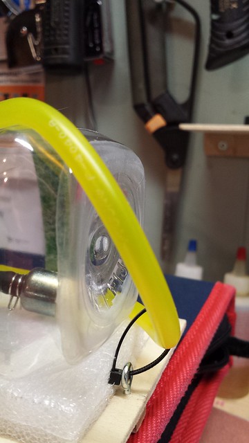
Fuel dot installed.

Vent line fitting installed.

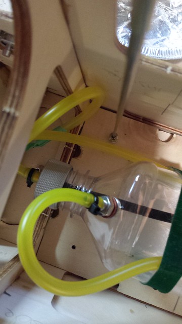
Complete fuel system installed, though not connected. I tape off all open ends to prevent dirt from entering the lines.

Fuel dot installed.
Vent line fitting installed.
Complete fuel system installed, though not connected. I tape off all open ends to prevent dirt from entering the lines.
12-21-2014, 05:50 PM
#221
I have done this with all of my builds for some time now. It provides a convenient hang point at the cg for front to rear and side to side balancing. On a low-wing plane, I put the eyebolt on the bottom, closer to the actual cg.
When questioned what the eyebolt on the top is, I say it is a loop antenna for my on-board direction finder. Anyone remember those?
Merry Christmas to All.
Sincerely, Richard
When questioned what the eyebolt on the top is, I say it is a loop antenna for my on-board direction finder. Anyone remember those?
Merry Christmas to All.
Sincerely, Richard
12-21-2014, 05:53 PM
#222
Senior Member
Thread Starter
Here is the complete two-line gas tank strapped to the tray. The green bands are Velcro plant ties from Lee Valley Tools - a steal at $3.80 for a 30' roll.
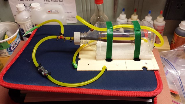
A loop at the back for the vent line.
The tank tray bolts with their two washers were hard to put in place with the tank in the way. Here's a way around it: grab the bolt and washers with a magnetic pickup tool...
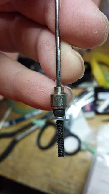
... and put the bolt in the hole.
Once the bolt is in place, slide the pickup tool off the bolt.
A loop at the back for the vent line.
The tank tray bolts with their two washers were hard to put in place with the tank in the way. Here's a way around it: grab the bolt and washers with a magnetic pickup tool...
... and put the bolt in the hole.
Once the bolt is in place, slide the pickup tool off the bolt.
12-21-2014, 06:00 PM
#223
Senior Member
Thread Starter
The central pull-pull rudder servo is in place, as are the two aileron servos.

Muffler is on and main gear is remounted.

Just a few more things to install and I'll be ready to check the balance.
Muffler is on and main gear is remounted.
Just a few more things to install and I'll be ready to check the balance.
12-21-2014, 06:12 PM
#224

I have done this with all of my builds for some time now. It provides a convenient hang point at the cg for front to rear and side to side balancing. On a low-wing plane, I put the eyebolt on the bottom, closer to the actual cg.
When questioned what the eyebolt on the top is, I say it is a loop antenna for my on-board direction finder. Anyone remember those?
Merry Christmas to All.
Sincerely, Richard
When questioned what the eyebolt on the top is, I say it is a loop antenna for my on-board direction finder. Anyone remember those?
Merry Christmas to All.
Sincerely, Richard
Last edited by thailazer; 12-21-2014 at 07:00 PM.
12-27-2014, 06:19 PM
#225
Senior Member
Thread Starter
I did NOT expect this to fit without modification.

As expected I did have to ream the spinner back plate and the prop to install them. No problems there.

MAS prop hubs are not solid, which would pose a problem for the DLE 30 and its four prop bolts if I had not installed a single bolt prop adapter.

I stuffed the throttle and choke servos, ignition and switch into a bag.

As expected I did have to ream the spinner back plate and the prop to install them. No problems there.
MAS prop hubs are not solid, which would pose a problem for the DLE 30 and its four prop bolts if I had not installed a single bolt prop adapter.
I stuffed the throttle and choke servos, ignition and switch into a bag.

