


AMR Trainer 26 - (my) official build thread
 04-21-2015, 05:18 PM
#426
Senior Member
Thread Starter

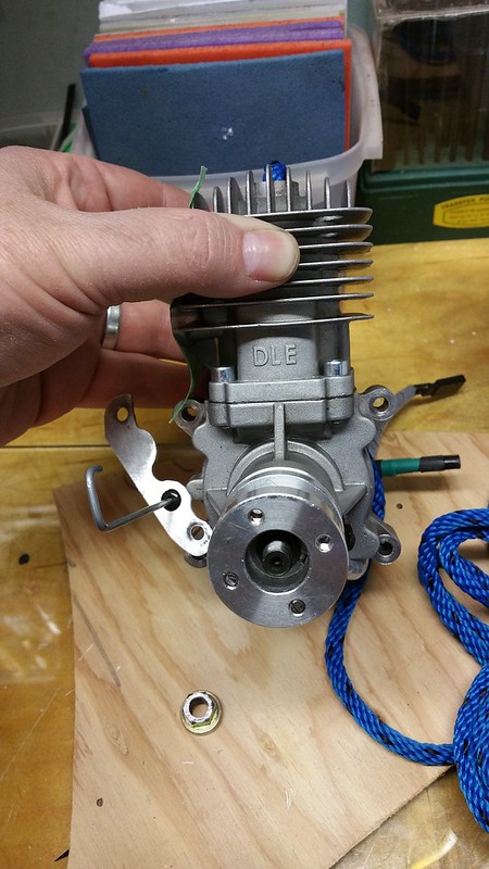
Pulled the hub tonight.
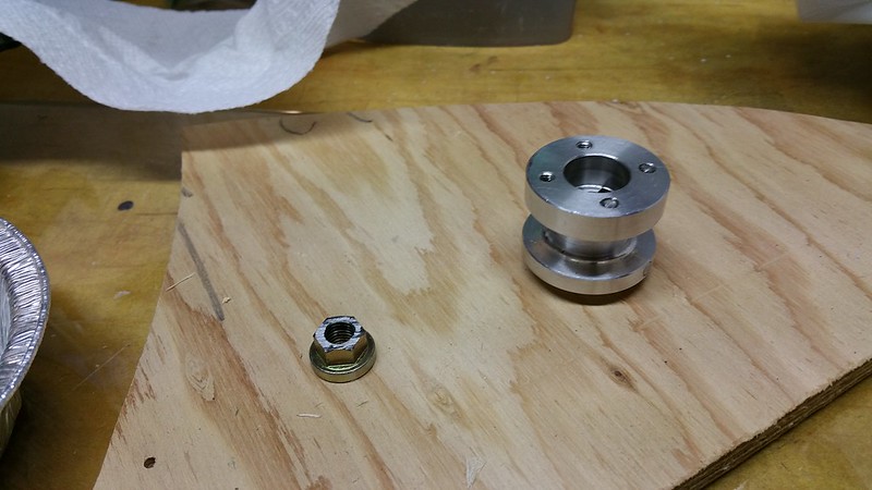
Crankshaft nut removed.
Small puller from Dad's toolbox (thanks Dad!) after cleaning and oiling. Note the heat shrink on the jaws.

Needed a spacer for the last little bit.

Hub off.
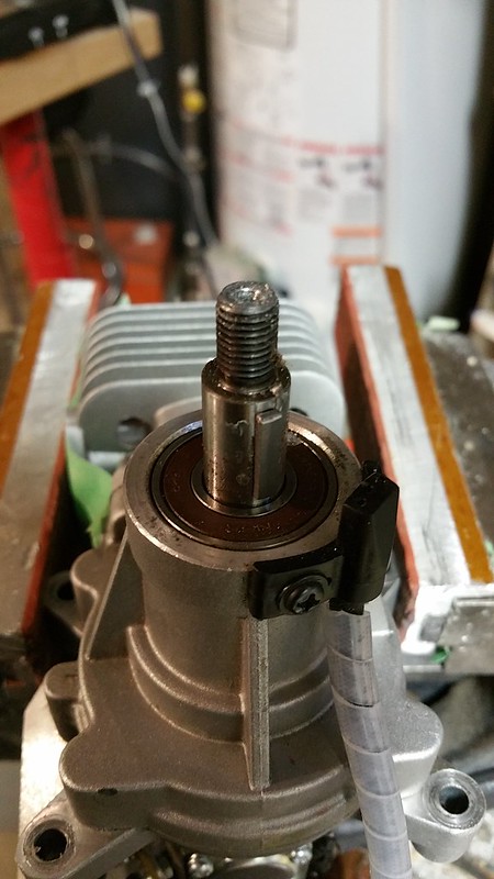
Crankshaft and front bearing exposed.
Crankshaft nut removed.
Small puller from Dad's toolbox (thanks Dad!) after cleaning and oiling. Note the heat shrink on the jaws.
Needed a spacer for the last little bit.
Hub off.
Crankshaft and front bearing exposed.
 04-21-2015, 05:22 PM
#427
Senior Member
Thread Starter
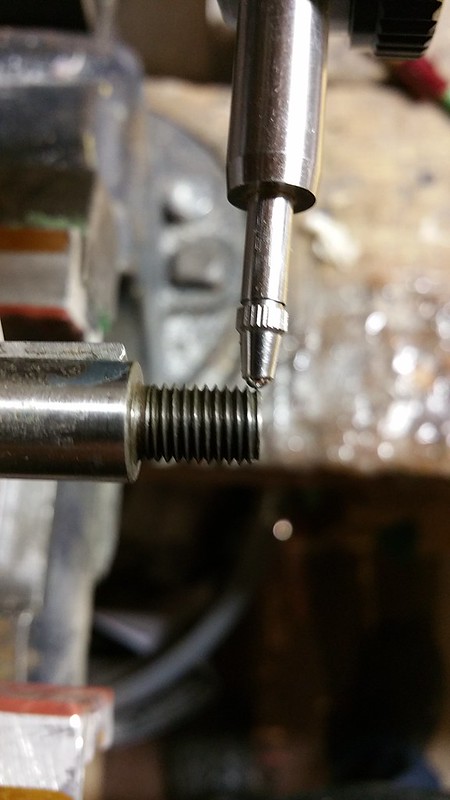
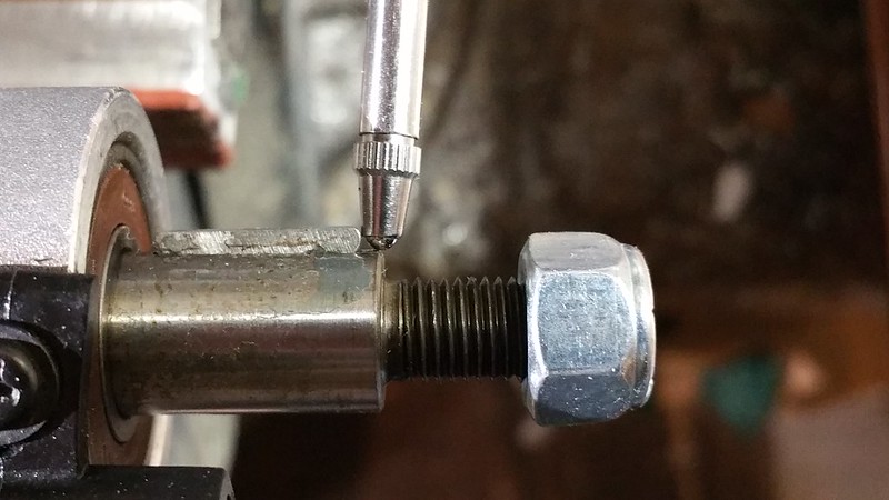
Dial indicator on crankshaft.

Pointer on threaded shaft. I think this affected accuracy during the test - see the video below.
DLE 30 - runout measured from crankshaft
- - -
Pointer on threaded shaft. I think this affected accuracy during the test - see the video below.
DLE 30 - runout measured from crankshaft
- - -
04-21-2015, 06:34 PM
#428

My Feedback: (1)
grosbeak, Move your dial indicator back to just where the real crankshaft nose starts, just aft of the threaded section and retake your run out test. Get the woodruff key out of the way and you will be able to get almost a full rotation (maybe 350 degrees or so). If you still get .003"-.004" run out shown, then yes the crank is bent. I don't trust the reading off the threaded area of the crank. From past experience building automobile engines, I would guess that on an engine this small no more than .0005"-.001" crank run out would be acceptable.
04-22-2015, 03:06 AM
#429
Senior Member
Thread Starter
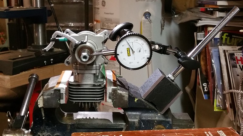
Runout test #3 - on a smooth portion of the crankshaft (just barely).
DLE 30 - runoff measured on smooth crankshaft
The dial indicator is steady except when the Woodruff key passes - this seems to tell a different story entirely.
Pictures of the setup...
DLE 30 - runoff measured on smooth crankshaft
The dial indicator is steady except when the Woodruff key passes - this seems to tell a different story entirely.
Pictures of the setup...
04-22-2015, 03:55 AM
#430
What was the runout, on both the face and the outer diameter, of the hub before you removed it from the engine? Interesting that your puller was made in Japan, not China, a real antique.
Sincerely, Richard
Sincerely, Richard
04-22-2015, 07:44 AM
#431
My Feedback: (1)
grosbeak, The photo shows .003" runout at the front of the machined hub area of the crank. From that, I disagree with your take that "this seems to tell a different story entirely". This is about I would expect in that area IF your reading off the threads was valid, and I now think it was. If the crank is bent, starting at the front bearing, the further forward you take a measurement the larger the runout reading will be. This is what your dial indicator shows. If you feel your setup and readings from the dial indicator are accurate (the setup didn't get knocked out of wack as it passed the key area) then one would have to conclude that the nose of the crank is bent and that would be consistent with the engine being in a nose first impact (crash). As spaceworm points out runout readings off the hub face and O.D. would have been good information. I think you could reinstall the hub and retainer nut and take those readings for further proof. Have you researched from the engine manufacturer any specs on this? I know .003 will be out of spec, it's too much. Also, question.....was the prop well balanced? I chuckled at spaceworm noticing that the puller was made in Japan not China. The made in Japan one is likely far superior.
04-22-2015, 08:20 AM
#432
My Feedback: (1)
grosbeak, OK, I take it all back. I had not viewed the You Tube video before commenting, I only saw the still photo and it showed .003 runout. You didn't zero the dial indicator and all I saw was .003" shown. Now I clicked on the You Tube video and I agree that it didn't show much if any runout. Back to square one.....I don't know. I would do the reinstall of the hub and take the face and O.D. readings though. The face of the hub is where the prop was mounted and it being square to the rotation of the engine is important. Sorry I went out into left field a little without watching the video. The whole thing with the broken prop mount bolts would make you think something was out of balance, but maybe it was bad or over stressed bolts. Going back to my remark about the made in Japan puller being superior to a made in China one, the same thing applys to the bolts. Ten or twelve years ago the full scale aviation industry was plagued with fake, inferior, aircraft hardware (bolts) made in, you guessed it, CHINA ! They looked just the real ones, had all the correct markings, but were inferior in strength and were failing. Jet engine pylon mount bolts I think. If you can't find anything else conclusive with your problem I might reinstall everything using known quality bolts and try again.
04-22-2015, 06:27 PM
#433
Senior Member
Thread Starter
What was the runout, on both the face and the outer diameter, of the hub before you removed it from the engine? Interesting that your puller was made in Japan, not China, a real antique.
I didn't measure runout on the face, but on the side of the hub it was 0.004". And yes, I did notice the country of manufacture on the puller. It belonged to my Dad - he gave me all his tools when he and Mom became condo dwellers almost 20 years ago.
Sincerely, Richard
I didn't measure runout on the face, but on the side of the hub it was 0.004". And yes, I did notice the country of manufacture on the puller. It belonged to my Dad - he gave me all his tools when he and Mom became condo dwellers almost 20 years ago.
Sincerely, Richard
grosbeak, OK, I take it all back. I had not viewed the You Tube video before commenting, I only saw the still photo and it showed .003 runout. You didn't zero the dial indicator and all I saw was .003" shown. Now I clicked on the You Tube video and I agree that it didn't show much if any runout. Back to square one.....I don't know. I would do the reinstall of the hub and take the face and O.D. readings though. The face of the hub is where the prop was mounted and it being square to the rotation of the engine is important. Sorry I went out into left field a little without watching the video. The whole thing with the broken prop mount bolts would make you think something was out of balance, but maybe it was bad or over stressed bolts. Going back to my remark about the made in Japan puller being superior to a made in China one, the same thing applys to the bolts. Ten or twelve years ago the full scale aviation industry was plagued with fake, inferior, aircraft hardware (bolts) made in, you guessed it, CHINA ! They looked just the real ones, had all the correct markings, but were inferior in strength and were failing. Jet engine pylon mount bolts I think. If you can't find anything else conclusive with your problem I might reinstall everything using known quality bolts and try again.
 04-24-2015, 09:38 PM
#434
My Feedback: (13)
Hay grosbeak,
I've been watching this build from the beginning and into your first flight. I am awaiting your next test flights and how this model flies for you. I too would recommend some differential aileron on your model and I believe someone else has mentioned this to you already. I also use "CAR" - coupled aileron and rudder, in all my models. All models fly a bit different, so you will need to play with the degree of mixing, until you find the sweet spot for your type of flying.
You picked out some nice color combinations too and I liked the looks of the finished model.
Please keep us posted and more pictures.
Soft Landings Always,
Bobby of Maui
Last edited by Bob Paris; 04-24-2015 at 09:41 PM.
04-25-2015, 04:55 AM
#435
Senior Member
Thread Starter
Thanks for the tips Bobby... For a while when I was learning I got pretty good at remembering to use the rudder. Guess it's time to go back to basics and put bank and yank back on the shelf where it belongs!
