


Great Planes RV-4 40 Kit build thread
 01-29-2015, 03:06 PM
#1
Member
Thread Starter

Join Date: Aug 2013
Location: Wheaton, IL USA
Posts: 64
Likes: 0
Received 0 Likes
on
0 Posts
So, after reading so many build threads I've decided (before I get carried away and finish) to start a build thread for my new RV-4 40 kit.
I've been flying for 18 months and I am loving it. I've built some ARFs and found myself disappointed how fast they built - it was just a few nights of entertainment. Well, I recently built a Sig 4 Star 40 with Saito 56 and found the build a pleasure (still waiting to maiden).
My wife was kind enough to see what I was interested in on Ebay and surprise me with a new GP RV-4 40 kit a few weeks ago. I was nothing short of thrilled. I've just started the fuse, but let's catch everyone up from the start.
Let's begin!
PD
 01-29-2015, 03:17 PM
#2
Member
Thread Starter
Join Date: Aug 2013
Location: Wheaton, IL USA
Posts: 64
Likes: 0
Received 0 Likes
on
0 Posts
Following the instructions I began with the tail surfaces. This was already a clear change from the 4 Star 40 which had simple pre-cut balsa H/V stab and control surfaces. All that was required in the 4* was sanding leading/trailing edges.
It took a moment to get used to cutting precisely for maximum bonding surfaces and I noticed myself getting better after the H-stab. Medium CA used for most tasks, sometimes initial then later secondary applications.


It took a moment to get used to cutting precisely for maximum bonding surfaces and I noticed myself getting better after the H-stab. Medium CA used for most tasks, sometimes initial then later secondary applications.
01-29-2015, 03:29 PM
#3
Member
Thread Starter
Join Date: Aug 2013
Location: Wheaton, IL USA
Posts: 64
Likes: 0
Received 0 Likes
on
0 Posts
Surfaces were sanded smooth with 320 grit paper and leading / trailing edges were contoured. I resisted the temptation to cover these as soon as they were finished.
Rudder and v-stab were next. I have a Sullivan tailwheel spare, but considering this is a scale kit and I tell myself that it'll be landed carefully, I'll stick with the stock one (images to follow - uploading images not working).
PD
Last edited by marmalade1; 01-29-2015 at 03:32 PM.
01-30-2015, 01:18 PM
#4


Join Date: Oct 2013
Location: OKC
Posts: 198
Likes: 0
Received 0 Likes
on
0 Posts
I'm subscribed. Looking good so far.
I will be following with a lot of interest, I have one in the box for a build a little further down the road.
Have you decided on the engine yet?
Don
I will be following with a lot of interest, I have one in the box for a build a little further down the road.
Have you decided on the engine yet?
Don
01-31-2015, 04:41 AM
#5
Member
Thread Starter
Join Date: Aug 2013
Location: Wheaton, IL USA
Posts: 64
Likes: 0
Received 0 Likes
on
0 Posts
Thanks for subscribing Don. I'm going to use an OS Surpass 70 ii. It's going to be plenty powerful enough with a 13x6 and will provide a great 4S sound.
My only reservation is that the OS 70 is rather heavy, despite being within the specified range. To combat this I'm considering mini-servos (still in the 40+oz/inch range) for the wings. This would save 20g per servo for an 80g saving in the wing (100g saving if you include the throttle too). Also, I'll be using either a 700mAh or 1100mAh LiFe battery to add voltage and shave weight vs NIXX packs.
Sadly, I'm going on vacation today and will be unable to work on the plane until next week. I don't know what I'm going to do with myself after the children go to bed; it will be strange.
PD.
Last edited by marmalade1; 01-31-2015 at 05:33 AM.
 02-03-2015, 07:58 AM
#8
Member
Thread Starter
Join Date: Aug 2013
Location: Wheaton, IL USA
Posts: 64
Likes: 0
Received 0 Likes
on
0 Posts
WiFi on vacation! Fantastic.
I'm glad to see some interest here. Regarding power: I strongly prefer glow to electric. I believe electric is better in almost every way, but I just love the smell, sound and realism of glow. The OS 70 will be fun. I get the impression a wide variety of engines would work. Many seem to use 52 size 4 strokes for more scale flying. I just happened to have this gem available.
GWDawg, the kit is (so far) straightforward. After reading other threads, be sure to get the wing jig / spar flat before applying any CA. I warped my first wing half and spent a week wetting/twisting/correcting/over correcting to get it right. Then I left it a few days to be sure it didn't twist back. The second half was much faster and straighter to build using books for weights before applying CA. Photos to follow.
02-03-2015, 08:49 PM
#10
Member
Thread Starter
Join Date: Aug 2013
Location: Wheaton, IL USA
Posts: 64
Likes: 0
Received 0 Likes
on
0 Posts
I'm amazed how much cleaner my 4s planes are vs my 2s. Obviously, electric will be cleaner still.
I've ordered a Hobby King remote onboard glow starter that is powered off the rx battery. I'm realizing now that the cowl will likely be open around the cylinder head. Too late, I've bought it now. I still rather like the idea of one less thing to carry; push the button and it ignites the glow plug for 15s.
Here's some wing construction images:
02-03-2015, 09:17 PM
#11
Member
Thread Starter
Join Date: Aug 2013
Location: Wheaton, IL USA
Posts: 64
Likes: 0
Received 0 Likes
on
0 Posts
So, as described in my thread a week or so ago ("Well at least one wing isn't warped on my Great Planes RV-4 40 kit"), the left wing was eagerly constructed and CA'd without carefully ensuring the entire spar and jig was on the bench. I glued in a warp of about 1/4". Not pleasing.
To to rectify this (only my second kit) I consulted dozens of forum threads and asked the more experienced and capable builders on this forum. Following advice offered, I soaked the wing briefly in hot water (careful, be brief as more than a minute warped the sheeting dreadfully) and over-corrected the warp with heavy text books for DAYS. I re-wetted the areas periodically and finally removed the over-correcting shim for a few days. This took time.
When I was sure it was stable I cut off the jig on the trailing edge and crossed my fingers that it stays that way.
The right wing was much faster to build and was arrow straight on he jig.
The center section trailing edge was slow to build. Insert balsa block and trim 75% of it off is a good summary.
Importantly, don't skip a step and finish the center section sheeting before inserting *and trimming the dihedral brace to fit neatly within the upper and lower spruce spars*. Don't just mix up a large batch of epoxy, cover everything in it to then realize you aren't sure the center section is flush with the spars (which is where the wing gets its strength) to then need to do some very messy, epoxy covered trimming /desperate fiddling. That would be silly.
I used a series of rubber bands/clamps to ensure the dihedral brace was pushed firmly against the webbing/spars .... As far as I could see, everything was seated well.
02-03-2015, 09:41 PM
#12
Member
Thread Starter
Join Date: Aug 2013
Location: Wheaton, IL USA
Posts: 64
Likes: 0
Received 0 Likes
on
0 Posts
Again, compared to the simplicity of the Sig 4 Star 40, the ailerons and flaps took a long time (an evening, really).
Each side is constructed of 2 sheets, 2 leading edges, 8 ribs 2 control horn backplates.
The aileron and flap is made as one then cut in half at a step that is easy if you don't overlook clearly marking the center point, thus allowing a simple cut to produce two equal halves. Forgetting to do this simple step would be very silly and would cause unnecessary worry in making the separation of the two halves.
Another silly thing would be to get carried away and CA the sheeting over the ribs to seal the aileron/flap without adding the control horn support. If you are in this situation, I would suggest carefully cutting cord wise from the trailing edge either side of the missing backplates, wetting the balsa, waiting 5 m then gently lifting the sheeting to expose the site of the missing backplate, CAing it in place while holding it down with a screwdriver and then sealing he flap with CA would neatly hide a silly, silly mistake (imagine a self-deprecating sort of emoticon here).
Last edited by marmalade1; 02-03-2015 at 09:48 PM. Reason: I is sloppy with grammar
02-14-2015, 11:05 AM
#13
Member
Thread Starter
Join Date: Aug 2013
Location: Wheaton, IL USA
Posts: 64
Likes: 0
Received 0 Likes
on
0 Posts
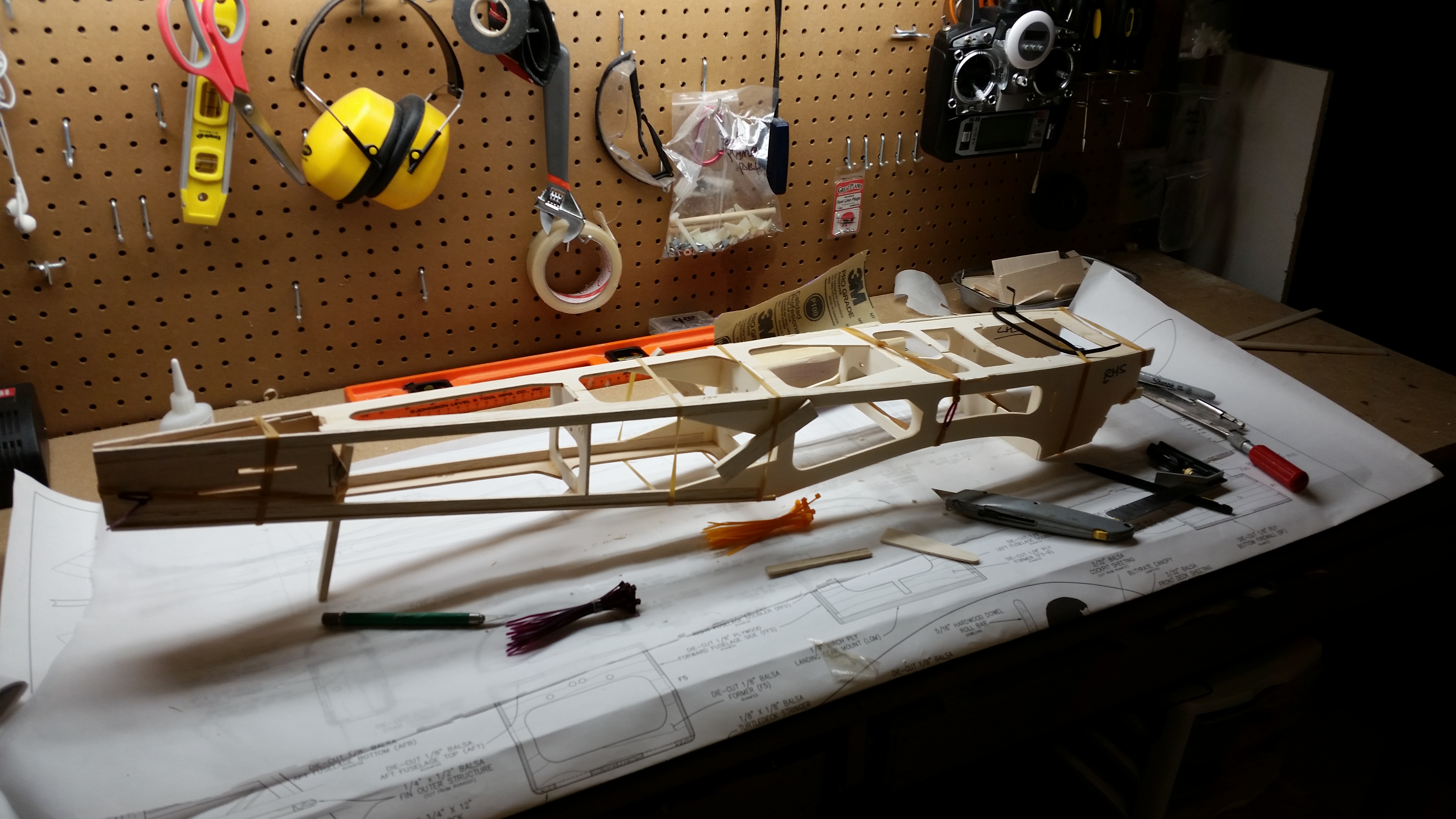
Back from vacation and onto building! Fuselage time!
My impatience in adding CA to the fuse introduced some permanent gaps towards the front. To address some of these I added tri-stock to the firewall.
The sheeting was uneventful. I would suggest letting damp balsa dry fully before trimming into final shape as it shrinks. Wet, curve overnight, trim. Learning every day.
Fuse went together fairly fast and with the wing almost complete it's really looking like an RV-4 40. It was surprising how poorly several parts fitted together (see images) some parts were several MM off; this was quite disconcerting. I reasoned that most of the problems didn't matter as long as the fuse was straight and not warped.
The firewall seems severely angled to the right, more than I'd anticipated from previous planes. I may add a washer or two to the engine mount to reduce this angle.
02-19-2015, 12:55 PM
#15
Member
Thread Starter
Join Date: Aug 2013
Location: Wheaton, IL USA
Posts: 64
Likes: 0
Received 0 Likes
on
0 Posts
So, building continued this week with several hours of work resulting in apparently modest progress. It's funny how early on 2 evenings makes a wing or a fuselage, but later on the same time offers more modest looking advances.
The sheeting on the turtledeck went smoothly with wetting, waiting and CA. This time I learnt to make final trimming after the balsa has dried as it shrinks somewhat. Lightweight spackle will fill the voids.


The cockpit floor went into place nicely.

Again, wetting, waiting until dry, then trimming provides the best margins. CA and sand.


Wing placement was carefully undertaken. Wing contours closely fitted the fuse. The trailing edge of the wing was a less ideal fit. The leading edge of the wing has a small 'box' added to it to offer a more streamlined appearance as it connects with the fuse. This is the sort of thing that I've become accustomed to with my first scale build; spending time on things that are not 'flight-critical'.
PD.
The sheeting on the turtledeck went smoothly with wetting, waiting and CA. This time I learnt to make final trimming after the balsa has dried as it shrinks somewhat. Lightweight spackle will fill the voids.
The cockpit floor went into place nicely.
Again, wetting, waiting until dry, then trimming provides the best margins. CA and sand.
Wing placement was carefully undertaken. Wing contours closely fitted the fuse. The trailing edge of the wing was a less ideal fit. The leading edge of the wing has a small 'box' added to it to offer a more streamlined appearance as it connects with the fuse. This is the sort of thing that I've become accustomed to with my first scale build; spending time on things that are not 'flight-critical'.
PD.
Last edited by marmalade1; 02-20-2015 at 08:24 AM.
02-19-2015, 01:41 PM
#16
Join Date: Oct 2013
Location: OKC
Posts: 198
Likes: 0
Received 0 Likes
on
0 Posts
Looks good, you are coming right along. In the last photo it looks like you have the engine installed and the cowl fit, can you post some photos of that? Did you use the kit supplied cowl pieces?
Don
Don
02-19-2015, 02:04 PM
#17
Member
Thread Starter
Join Date: Aug 2013
Location: Wheaton, IL USA
Posts: 64
Likes: 0
Received 0 Likes
on
0 Posts
Don, the cowl is... a challenge. I've trimmed most of the upper and lower but I can't determine the correct 'finish line' to bond. After a long time fiddling, I decided to proceed with the rest and then come back to it. The lower is screwed in at the bottom (more discrete than the suggested site). I've visited the Stans Fiberglass site several times... but I'll try this one first. Screwing in the bottom helped align the upper as there is more stability when holding parts.
I'd appreciate any images of 'cut lines' from any people that have finished a GP RV-4 40.
PD.
I'd appreciate any images of 'cut lines' from any people that have finished a GP RV-4 40.
PD.
03-06-2015, 08:04 AM
#18
Member
Thread Starter
Join Date: Aug 2013
Location: Wheaton, IL USA
Posts: 64
Likes: 0
Received 0 Likes
on
0 Posts
An early image of my method (1st time, remember) of aligning the top and bottom cowls. I screwed in the lower for stability and wanted to ensure the upper portion of the cowl was flush to the fuselage. The rubber bands helped secure both allowing better alignment / marking /cutting.
Exciting times. Installation of servos. Note use of Mini-servo for throttle. I'm going to use the suggested two rods for the elevator; it seems to offer no advantage, but it will be interesting to try a different set up.
PD
Last edited by marmalade1; 03-06-2015 at 08:47 AM.
03-06-2015, 08:54 AM
#19
Member
Thread Starter
Join Date: Aug 2013
Location: Wheaton, IL USA
Posts: 64
Likes: 0
Received 0 Likes
on
0 Posts
Next up: Onboard glow ignitor. Despite recently realizing the OS Surpass 70ii would still protrude from the cowl somewhat I thought it would be rather neat to have an ob-board glow ignitor. This set-up adds just a few grams to the weight and would allow a cleaner cowl and more convenience at the field. Most importantly, it's cool.
I decided to add the ignition button to the underside of the cowl for esthetic reasons. I expect I'll add the on/off switch there too as it won't get knocked and will be clean looking. I'll have to be careful not to burn my fingers on the exhaust though.


I used velcro to attach the circuitry to the top of the F1/tank area. This will provide some vibration relief and allow quick access. I'll use the rx battery for power. I was tempted to use a very small Lipo (100-130mAh) for power however the fear of accidentally leaving it on (and causing a fire) is not worth it.
I decided to add the ignition button to the underside of the cowl for esthetic reasons. I expect I'll add the on/off switch there too as it won't get knocked and will be clean looking. I'll have to be careful not to burn my fingers on the exhaust though.
I used velcro to attach the circuitry to the top of the F1/tank area. This will provide some vibration relief and allow quick access. I'll use the rx battery for power. I was tempted to use a very small Lipo (100-130mAh) for power however the fear of accidentally leaving it on (and causing a fire) is not worth it.
Last edited by marmalade1; 03-06-2015 at 09:03 AM. Reason: Adding more details.
03-06-2015, 09:53 AM
#20
Join Date: Oct 2013
Location: OKC
Posts: 198
Likes: 0
Received 0 Likes
on
0 Posts
The build is looking good.
I was wondering how much the .70 would stick out of the cowl, as it turns out not much. Even though I won't be building mine for some time as I am just getting started in this hobby, I have decided to spring for the fiberglass cowl when that time comes. What brand of on-board glow igniter is that?
I am also going to be interested in the finished weight and how it balances out with the .70 up front.
Don
03-06-2015, 10:30 AM
#21
Member
Thread Starter
Join Date: Aug 2013
Location: Wheaton, IL USA
Posts: 64
Likes: 0
Received 0 Likes
on
0 Posts
Don,
The engine doesn't stick out much but, it's still a hole. The 52/56 size I hear is enclosed and perfectly adequate. I just happened to have this one. The on-board glow ignitor was about $8 from Hobby King. Seems like great value. Press the button and your plug will glow for 15s. About the perfect time really. Light too.
Early testing of the CG revealed a severe nose-heavy situation. I'm looking into mounting the LiFe battery, likely 1100mAh, right at the tail and creating a hatch. This is new territory for me; I hate to mess with a good design, but I'm loathe to add what would be 2-4 oz to the tail. The 5 mini-servos will help moderate the planes weight. I have to think of a secure hatch design. I'll velcro the battery in (very secure in my opinion, just try to shake it off) and have an esthetic hatch on the bottom with one or two small latches (recently bought from HK for a few dollars). As I say, it's new to me.
PD.
Last edited by marmalade1; 03-06-2015 at 11:46 AM.
03-09-2015, 11:43 AM
#22
Member
Thread Starter
Join Date: Aug 2013
Location: Wheaton, IL USA
Posts: 64
Likes: 0
Received 0 Likes
on
0 Posts
Wing servo installation and covering. I've decided to go with a bright orange covering for the bottom of the wings/horizontal stabilizer/elevator. I like the relative contrast to the white that is going to be on most of the upper. Looking at many examples of the RV-4 on Google images it seems most people go with a simple white with stripes at the tips. This scheme suits my limited talent / ambition.
The material is Value Hobby's Neucover. I first used it on my Sig 4 Star 40 and was shocked by it's ease of use; it is very thin (vs. the 17 year old Monokote I've previously used that is now lifting off my Sig Somethin' Extra) it tacks easily and shrinks very, very well. It's thinness allows margins to be subtle. I'm a fan. Also, it's just $12 for 15' (Siccum).


It's great to be able to add the servos and see the wing come to life. I used GP CA hinges. I prefer Value Hobby's CA hinges as they are stiffer and easier to insert all at once without crushing. Also, the fibers of the GP CA hinges seem to peel off (although still better than the Sig Easy Hinges which just split as soon as you try to insert them - in my hands at least).
I added a Turnigy (HK) "3 channel servo speed/direction regulator" to the flaps. This inexpensive ($8) and lightweight device will allow my flaps to move slowly and smoothly. This is important not just to look 'scale' but to help prevent sharp pitch changes when flaps are deployed/retracted.
The instructions are lacking for the product, so just do what I did:
1) Place it in-line with the Y-connector for the flaps
2) Fiddle with the plug/pots until it works how you want.
PD
The material is Value Hobby's Neucover. I first used it on my Sig 4 Star 40 and was shocked by it's ease of use; it is very thin (vs. the 17 year old Monokote I've previously used that is now lifting off my Sig Somethin' Extra) it tacks easily and shrinks very, very well. It's thinness allows margins to be subtle. I'm a fan. Also, it's just $12 for 15' (Siccum).
It's great to be able to add the servos and see the wing come to life. I used GP CA hinges. I prefer Value Hobby's CA hinges as they are stiffer and easier to insert all at once without crushing. Also, the fibers of the GP CA hinges seem to peel off (although still better than the Sig Easy Hinges which just split as soon as you try to insert them - in my hands at least).
I added a Turnigy (HK) "3 channel servo speed/direction regulator" to the flaps. This inexpensive ($8) and lightweight device will allow my flaps to move slowly and smoothly. This is important not just to look 'scale' but to help prevent sharp pitch changes when flaps are deployed/retracted.
The instructions are lacking for the product, so just do what I did:
1) Place it in-line with the Y-connector for the flaps
2) Fiddle with the plug/pots until it works how you want.
PD
03-09-2015, 12:01 PM
#23
Member
Thread Starter
Join Date: Aug 2013
Location: Wheaton, IL USA
Posts: 64
Likes: 0
Received 0 Likes
on
0 Posts
Completing much of the wing allowed me to re-assess the center of gravity. As before, it was very nose-heavy. I Balanced it inverted with the prop/cowl/empty tank and placed the 1100mAh LiFe (GForce) battery on the back of the fuse. It was still too nose-heavy.
Reluctantly, I added about 3oz of lead to the horizontal stabilizer (further back than the battery could go). This allowed a good balance. In an effort to hide this weight - which by the way was almost exactly the same amount of weight as was saved using the mini-servos - I noticed that I could hide the lead in the stick structure of the V/H-stabs.
To ensure a good fit I cleaned the lead with alcohol, covered the edges with 5min epoxy and wedged them in. They all had good primary stability and when the epoxy sets and it is covered, will provide a good result.


PD
Reluctantly, I added about 3oz of lead to the horizontal stabilizer (further back than the battery could go). This allowed a good balance. In an effort to hide this weight - which by the way was almost exactly the same amount of weight as was saved using the mini-servos - I noticed that I could hide the lead in the stick structure of the V/H-stabs.
To ensure a good fit I cleaned the lead with alcohol, covered the edges with 5min epoxy and wedged them in. They all had good primary stability and when the epoxy sets and it is covered, will provide a good result.
PD
Last edited by marmalade1; 03-09-2015 at 12:05 PM.
03-20-2015, 08:42 AM
#24
Member
Thread Starter
Join Date: Aug 2013
Location: Wheaton, IL USA
Posts: 64
Likes: 0
Received 0 Likes
on
0 Posts
Work continues this week with covering the fuselage. Again I'm using Value Hobby's Neucover. I started as suggested with the bottom back, and worked my way forward.
The adhesive didn't work as well on the engine compartment areas that were covered with polyurethane, as expected, but the addition of a small quantity of CA and a heat iron quickly adhered all the foremost trim.
I covered the fuse all the way to the back and trimmed out the areas into which the H and V stabilizers would slot. I then marked area of covering to be removed on H and V stab and used a mild excess of 5 min epoxy to attach. Alcohol was used to wipe the areas clean after alignment was eyeballed from near and far. The rudder hinge was also epoxied at this time into the slot at the rear with an excess of epoxy to ensure long-term attachment even on heavy landings.
I couldn't resist trimming the canopy and seating the anxious pilot. I found I had some old canopy rubber trim. I'm 2" shy of covering the base but decided to leave the open area at the back. I'm looking for a simple black paint for the cabin. I'm going to add the roll cage for added realism.
Last edited by marmalade1; 03-28-2015 at 07:30 AM. Reason: Spelling
03-26-2015, 04:02 PM
#25
Member
Thread Starter
Join Date: Aug 2013
Location: Wheaton, IL USA
Posts: 64
Likes: 0
Received 0 Likes
on
0 Posts
Added tail stripes. Looking good. Happy I bought some trim tape; it really adds a sharp edge to the stripes. Next up: Wing stripes.
Eventually, I'll get around to finishing the cowl. I can't believe how much time I've spent on it so far and it still looks poor.
Stay tuned.
PD