


Meister scale P-47 D-25 Diary of a scale build


 05-06-2015, 04:52 AM
#52

I have started to look for the scheame as it is best to have your documentation before you start the build.
So fare "Angie" is still in the mix with all the history and pictures available.
There is a lot of documentation on the plane.


I am also looking at this P-47D bubbletop as Chief Ski-U-Mah II
I like the overall scheame of this and Amy will be able to do a great job on the noes art.
There is not a lot of pics or documentation that I have found......yet!


I will keep looking and will pick one before I start building.
TB
So fare "Angie" is still in the mix with all the history and pictures available.
There is a lot of documentation on the plane.
I am also looking at this P-47D bubbletop as Chief Ski-U-Mah II
I like the overall scheame of this and Amy will be able to do a great job on the noes art.
There is not a lot of pics or documentation that I have found......yet!
I will keep looking and will pick one before I start building.
TB
07-15-2015, 01:16 PM
#53
Ok guys with Miss Fire done and my bench cleared, talked to Dino today and my kit shipped today, got traking and waiting on a delivery date. Should be here next week. I will start as soon as I get it settled into my shop.
Round four, here we go.
TB
Round four, here we go.
TB
08-04-2015, 04:04 AM
#54
Now that I have my first Scale Masters qualifier under my belt I know what I need to do. It really showed how important the documentation is. There was a CARF P-47 that was in the export division and it really got hit on documentation and lack of detail. It was a nice model but basically an ARF in my opinion.

Also I learned a lot about the flying as it is the more dificult part of compeating. To see how a big bird like this flies scale and stands out was really cool.
So I will start to do my resurch on my documentation. Building starts soon as I am prepping my build area and getting all my stuff together.
I also got a lot of good information on setting up a plane like this. This CARF had a redundant air system for the landing gear. First system is an over the counter setup that will automatically drop your gear if air pressure falls to low. If that fails there is a one time (per flight) blow down setup. It is a seporate tank, valve and a check valve that will blow down your gear. This was simple and home made.
So now I need to get busy.
TB
08-09-2015, 11:33 AM
#55
I am starting to plan the stab and control surfaces. The parts are cut for a typical RC bevel hinge and just adding the scale pocket pushes the hinge line back a 1/4" so I may cut the ribs back 1/4" so that the hinge line and the size of the tail section remains the same. I have yet to find a 3 view drawing that matches the size of the stab. They all seem smaller when I blow them up to fit the overall size of my plan.

So I am dry fitting parts and seeing what I may need to do to acomidate the scale torque rod, bearings and scale hinges.

Also do I want to use the lighter carbon fiber rod or the aluminum tube. The control horn will be bolted threw so a wood dowl will be inserted at that point if I go with the carbon fiber. As long as there is no friction the carbon fiber will do fine, but any friction it needs to be aluminum. Also color is an issue. The black will have to be painted, the aluminum is natural so a few things to think about. Right now the 3/8" rod seems the right fit, I have everything to do this if I go 1/4" so still looking at it. The main thing is do I cut the ribs back for the stab 1/4".
TB
So I am dry fitting parts and seeing what I may need to do to acomidate the scale torque rod, bearings and scale hinges.
Also do I want to use the lighter carbon fiber rod or the aluminum tube. The control horn will be bolted threw so a wood dowl will be inserted at that point if I go with the carbon fiber. As long as there is no friction the carbon fiber will do fine, but any friction it needs to be aluminum. Also color is an issue. The black will have to be painted, the aluminum is natural so a few things to think about. Right now the 3/8" rod seems the right fit, I have everything to do this if I go 1/4" so still looking at it. The main thing is do I cut the ribs back for the stab 1/4".
TB
Last edited by TonyBuilder; 08-09-2015 at 11:45 AM.
08-14-2015, 04:09 AM
#57
Thanks Bob, I am changing gears and starting on the fuselage as I need more time to figure out what I want to do with the stab.
The plans take time to read and figure what goes where. Manuel is minimal so the start is low going. I bet once I do get going it will go faster.
TB
The plans take time to read and figure what goes where. Manuel is minimal so the start is low going. I bet once I do get going it will go faster.
TB
08-16-2015, 05:31 AM
#61
So I am starting on the fuselage.
I am using 1/2" drywall as my building pin board. On a solid door.
I laid the plans and covered with painters plastic, checking that it was strait with a strait edge.


The plans and instructions have no mention of the crutch, only that the fuselage builds on it. So I dug threw the supplied sticks and found the only option, 3/8"x3/8" balsa sticks.
I was short one stick so this gave concern that I was using the wrong material, but it was the only thing supplied, I'm guessing just got shorted one stick.
I spliced two together per side and pined one side to the plans then filling in the cross pieces as I went. I used yellow glue.


Once all the sticks were glued I cut a bunch of triangles out of 1/8" micro-lite ply.
These were glued with epoxy.


Formers 5 threw 8 are split, not sure why as all the other bigger ones are whole.
I am gluing them together with epoxy.


I will cut out a lot of the inner parts on formers 5 threw 7 to lighten the tail up.
Next I will fabricate the jig to build the fuselage on.
TB
I am using 1/2" drywall as my building pin board. On a solid door.
I laid the plans and covered with painters plastic, checking that it was strait with a strait edge.
The plans and instructions have no mention of the crutch, only that the fuselage builds on it. So I dug threw the supplied sticks and found the only option, 3/8"x3/8" balsa sticks.
I was short one stick so this gave concern that I was using the wrong material, but it was the only thing supplied, I'm guessing just got shorted one stick.
I spliced two together per side and pined one side to the plans then filling in the cross pieces as I went. I used yellow glue.
Once all the sticks were glued I cut a bunch of triangles out of 1/8" micro-lite ply.
These were glued with epoxy.
Formers 5 threw 8 are split, not sure why as all the other bigger ones are whole.
I am gluing them together with epoxy.
I will cut out a lot of the inner parts on formers 5 threw 7 to lighten the tail up.
Next I will fabricate the jig to build the fuselage on.
TB
08-16-2015, 01:28 PM
#64
I got the jig built.
I dry fitted the formers on the jig.
The crutch from former 6 threw 1 is to wide. I built it on the plans as shown but by the time I got to former #1 it was a 1/4" to big.


1 and 2 are the worst so I will only deal with them. The rest I will center and sand the crutch to fit them after gluing.
More dry fitting to make sure my jig is good and the formers fit.


I put the crutch back on the plans and cut the front brace and the second brace. I then cut a new 3/8x3/8 stick the correct length and glued it in with epoxy. I did the same on the secod brace and glued a 1/4x3/8 base wood stick to it.


I set the jig back up and placed the formers in the crutch.


The fit on former 1 and 2 is much better, 3 and 4 are not tight but I can live with that.


The jig is only held in place with weights. I might tack it down after I glue the formers in.


I will let this sit and look it over to make sure I did not miss anything. When I do glue them in it will be one at a time with 30min epoxy.
TB
I dry fitted the formers on the jig.
The crutch from former 6 threw 1 is to wide. I built it on the plans as shown but by the time I got to former #1 it was a 1/4" to big.
1 and 2 are the worst so I will only deal with them. The rest I will center and sand the crutch to fit them after gluing.
More dry fitting to make sure my jig is good and the formers fit.
I put the crutch back on the plans and cut the front brace and the second brace. I then cut a new 3/8x3/8 stick the correct length and glued it in with epoxy. I did the same on the secod brace and glued a 1/4x3/8 base wood stick to it.
I set the jig back up and placed the formers in the crutch.
The fit on former 1 and 2 is much better, 3 and 4 are not tight but I can live with that.
The jig is only held in place with weights. I might tack it down after I glue the formers in.
I will let this sit and look it over to make sure I did not miss anything. When I do glue them in it will be one at a time with 30min epoxy.
TB
Last edited by TonyBuilder; 08-16-2015 at 02:51 PM.
 , and just watch.
08-17-2015, 04:23 AM
, and just watch.
08-17-2015, 04:23 AM
#66
[TABLE="width: 100%"]
[TR]
[TD="class: smText, width: 80%"][/TD]
[TD="width: 20%, align: right"][/TD]
[/TR]
[TR]
[TD="colspan: 2"]Glad I'm taking my time. I had the crutch upside down. So I flipped the formers so the bottom is now up and all the triangle braces are facing to the bottom.[/TD]
[/TR]
[/TABLE]
I'm still working on what to do with the inner cooler doors and the tail wheel. I need to check the location on my 3- view drawings and then make adjustments if needed. I will glue in formers 1 threw 5. I will be removing some material from formers 6 threw 8 to lighten up the tail, won't be much but anything helps.
Former F9 is also a 1/4" to small so not sure what to do with this. I can cut a new one and make it fit tight. Not sure why the crutch and the formers are not matching up. One fits tight, then the next is small, then the next is tight and so on, not consistent. I can't just sand the crutch as it will change the profile. I could add 1/8" all around to fir it out, still thinking on that. Any input on this would be great.
TB
[TR]
[TD="class: smText, width: 80%"][/TD]
[TD="width: 20%, align: right"][/TD]
[/TR]
[TR]
[TD="colspan: 2"]Glad I'm taking my time. I had the crutch upside down. So I flipped the formers so the bottom is now up and all the triangle braces are facing to the bottom.[/TD]
[/TR]
[/TABLE]
I'm still working on what to do with the inner cooler doors and the tail wheel. I need to check the location on my 3- view drawings and then make adjustments if needed. I will glue in formers 1 threw 5. I will be removing some material from formers 6 threw 8 to lighten up the tail, won't be much but anything helps.
Former F9 is also a 1/4" to small so not sure what to do with this. I can cut a new one and make it fit tight. Not sure why the crutch and the formers are not matching up. One fits tight, then the next is small, then the next is tight and so on, not consistent. I can't just sand the crutch as it will change the profile. I could add 1/8" all around to fir it out, still thinking on that. Any input on this would be great.
TB
08-17-2015, 05:17 AM
#67

My Feedback: (6)
T/B
Having never built a bird from a KIT cutter, and not being able to look over your shoulder, I think the first thing I would do is talk to the cutter, take,close up's of the problems to show them to get it resolved. If that does not work I assume the plans are complete and there are dwg's of all parts, if so have the plans copied and cut your own, but first out of poster/board to verify the plans are correct. in the old days it was not uncommon to get a kit that had that problem, so I just winged it and made my own, But at the cost of these cut kits, they should make it right.
Just my thoughts.
Cheers Bob T
08-18-2015, 02:33 AM
#68
Progress
i glued in all the formers short of F8a and 9. I used epoxy on 1&2, thin CA on the rest. I cut out the centers on formers 6,7 and 8. This added up to 2.2 oz of weight savings, that should even up the use of epoxy")
I also glued in the center stringer to keep everything in line. As to former #9 I will fir it out with 1/8 balsa strip and then sand it down to conform to the rest of the fuselage. I need to work on the tail gear next so I can glue in Fa and F9.
TB
i glued in all the formers short of F8a and 9. I used epoxy on 1&2, thin CA on the rest. I cut out the centers on formers 6,7 and 8. This added up to 2.2 oz of weight savings, that should even up the use of epoxy
I also glued in the center stringer to keep everything in line. As to former #9 I will fir it out with 1/8 balsa strip and then sand it down to conform to the rest of the fuselage. I need to work on the tail gear next so I can glue in Fa and F9.
TB
Last edited by TonyBuilder; 08-18-2015 at 02:38 AM.
08-18-2015, 05:35 AM
#69
So next is to figure how to mount the tail wheel retract so I can remove it and service it if needed. The Sierra is a flat mount style and sits in the fuselage so a hatch might be the best way to do this. The hatch would be all the details just in front of the gear doors and the scoop. This would be removable to expose the gear for installation and removal. Otherwise it's barred and I don't like that.
TB
TB
08-19-2015, 03:47 AM
#71
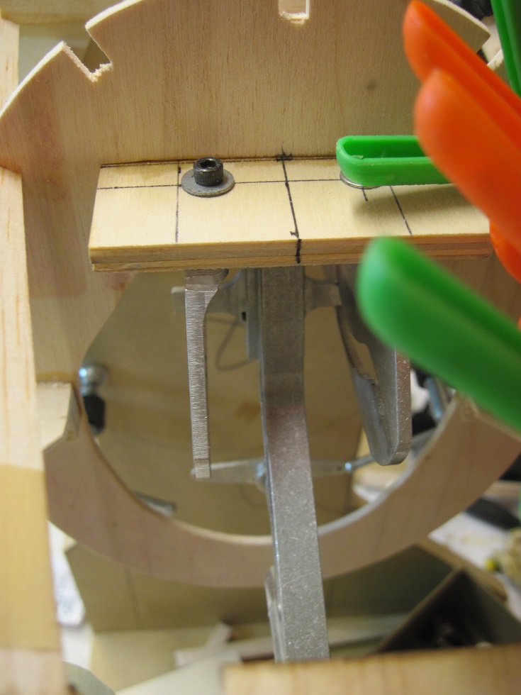
I am working on the tail wheel retract.
I am only dry fitting and checking for proper location and that it al works correctly.
The retract is mounted to a 1/4" ply base and this will get glued in to the formers 8 and 8a.


I made a new F8a as the one I have is to small so I made it I little larger to fit the crutch.


I am still checking for correct placement, and how deep to set it in the fuselage. This all has to be done by eye.
I am also making a new F9 former to accommodate the retract and plus it too is to small.
Once I get this all worked out I will glue it all in. The retract will drop down once unbolted and remove from the wheel well....in theory.
TB
I am only dry fitting and checking for proper location and that it al works correctly.
The retract is mounted to a 1/4" ply base and this will get glued in to the formers 8 and 8a.
I made a new F8a as the one I have is to small so I made it I little larger to fit the crutch.
I am still checking for correct placement, and how deep to set it in the fuselage. This all has to be done by eye.
I am also making a new F9 former to accommodate the retract and plus it too is to small.
Once I get this all worked out I will glue it all in. The retract will drop down once unbolted and remove from the wheel well....in theory.
TB
08-19-2015, 11:30 AM
#72
Tail wheel mount is all fabricated and glued in.
I cut a new modified F8a to support the section at the gear mount. This type of gear has the pull lines for steering at the top so when the gear goes inside the cables slack and the arm moves back.
So the 3/8x3x8 spreader block in the crutch has to be removed. The new F8q is a ring so it will hold the crutch in place.


For F9 I just split it in half and added some stock in the middle to fir it out to match the crutch, the spreader also gets cut out to allow the wheel to pass. It fits tight now.


Some side braces out of 1/8 micro-light ply to hold it all together.


The steering arm now swings free.


All glued up and drying.


I started on the WSD wing saddle sides. One set is in.


Starting a new project is hard simply because there is nothing there to work off.
Once you get into it, it start to move as each time you add to it, it becomes easier to build as now you have something to work off of.
Onward.
TB
I cut a new modified F8a to support the section at the gear mount. This type of gear has the pull lines for steering at the top so when the gear goes inside the cables slack and the arm moves back.
So the 3/8x3x8 spreader block in the crutch has to be removed. The new F8q is a ring so it will hold the crutch in place.
For F9 I just split it in half and added some stock in the middle to fir it out to match the crutch, the spreader also gets cut out to allow the wheel to pass. It fits tight now.
Some side braces out of 1/8 micro-light ply to hold it all together.
The steering arm now swings free.
All glued up and drying.
I started on the WSD wing saddle sides. One set is in.
Starting a new project is hard simply because there is nothing there to work off.
Once you get into it, it start to move as each time you add to it, it becomes easier to build as now you have something to work off of.
Onward.
TB
08-20-2015, 01:14 PM
#73
Daily progress
Fs1 doubler is glued in on the right side. Titebond was used for this.


Being I am doing working inner cooler doors I will be cutting out the center crutch between R6 and R7.
So I added a new stringer just above the opening to support the lack of the main center stringer.
I will add one below when I flip to install FS3


The outer FS1 is installed on the left side along with FS1a
I was having a hard time figuring where it goes as there is no exact location and I just centered it on the main crutch stringer.
I was all worried about the wing incidence but remembered Mierc had so add wood to his saddle and sand it to fit so I wont worry about that as I will check the incidence when I mount the wing and adjust it then.
Titebond was used for FS1 top laminate and CA for FS1A


F9A is glued in and will get cut once the other side is in for the retract wheel well.

The gear is all locked in and looking good. I will test it as soon as I get the rest of the right side installed.


TB
Fs1 doubler is glued in on the right side. Titebond was used for this.
Being I am doing working inner cooler doors I will be cutting out the center crutch between R6 and R7.
So I added a new stringer just above the opening to support the lack of the main center stringer.
I will add one below when I flip to install FS3
The outer FS1 is installed on the left side along with FS1a
I was having a hard time figuring where it goes as there is no exact location and I just centered it on the main crutch stringer.
I was all worried about the wing incidence but remembered Mierc had so add wood to his saddle and sand it to fit so I wont worry about that as I will check the incidence when I mount the wing and adjust it then.
Titebond was used for FS1 top laminate and CA for FS1A
F9A is glued in and will get cut once the other side is in for the retract wheel well.
The gear is all locked in and looking good. I will test it as soon as I get the rest of the right side installed.
TB
08-23-2015, 04:18 AM
#74
Progress
Both sides have Fs1 and Fs1A installed so I can now remove the fuselage off of the crutch jig.
I did a temp front building jig mount so I can use the rotating building jig from here on.


I am in the planning stage of where to put all my internal gear.
I am thinking the two air tanks will go between F2 and F3
I am working on the way I will mount them.
Fuel tanks in between F2 and F3 also.


Bats, throttle, and choke servos in between F1 and F2


Elevator, and ruder servos in between F4 and F5


Cockpit will be in between F3 and F4 so nothing goes in here until I get that in, I'm doing a full cockpit.


I need to figure how my pushrod for the elevator will be routed as the tail wheel is kind of in the way.
Ruder pull pull will get routed on either side.


I may have to build the stab next to align the elevator and ruder linkages as they will be internal.
TB
Both sides have Fs1 and Fs1A installed so I can now remove the fuselage off of the crutch jig.
I did a temp front building jig mount so I can use the rotating building jig from here on.
I am in the planning stage of where to put all my internal gear.
I am thinking the two air tanks will go between F2 and F3
I am working on the way I will mount them.
Fuel tanks in between F2 and F3 also.
Bats, throttle, and choke servos in between F1 and F2
Elevator, and ruder servos in between F4 and F5
Cockpit will be in between F3 and F4 so nothing goes in here until I get that in, I'm doing a full cockpit.
I need to figure how my pushrod for the elevator will be routed as the tail wheel is kind of in the way.
Ruder pull pull will get routed on either side.
I may have to build the stab next to align the elevator and ruder linkages as they will be internal.
TB
Last edited by TonyBuilder; 08-23-2015 at 04:44 AM.
