


Meister scale P-47 D-25 Diary of a scale build


 08-24-2015, 04:08 AM
#79
Progress.
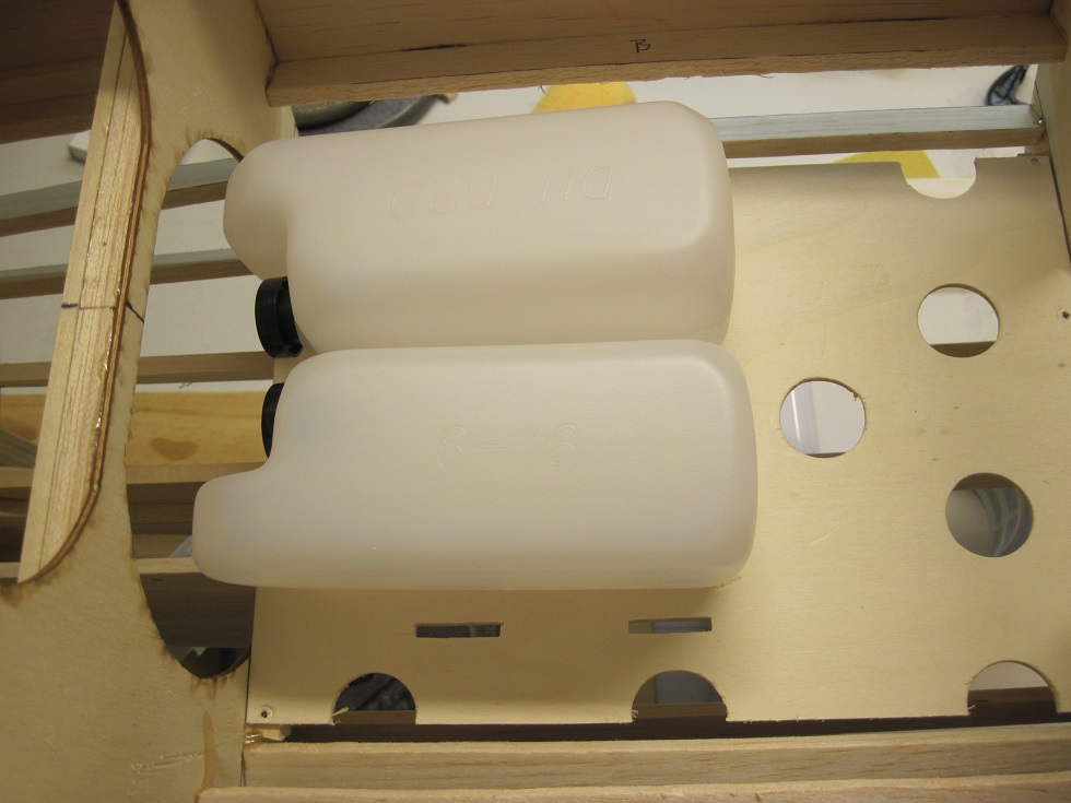
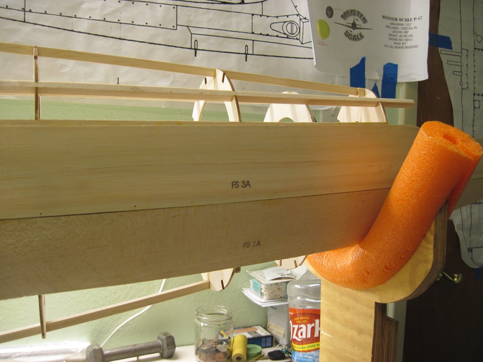
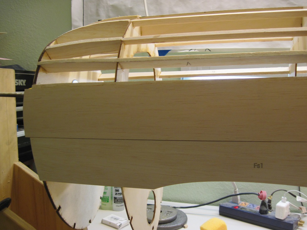
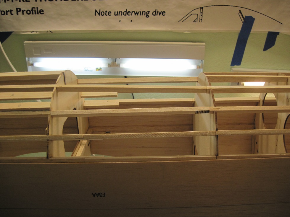
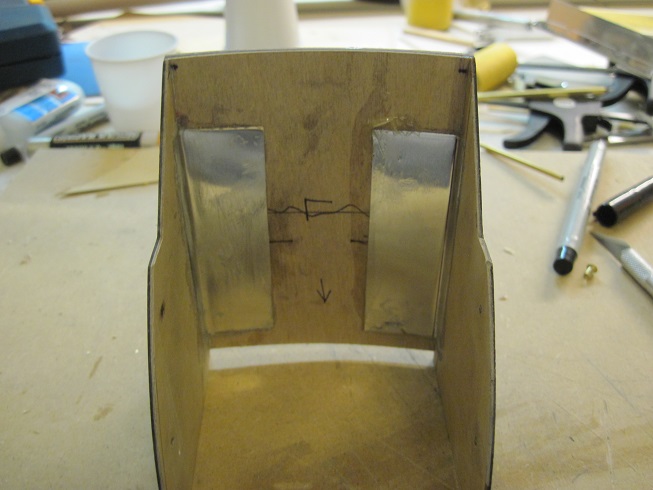
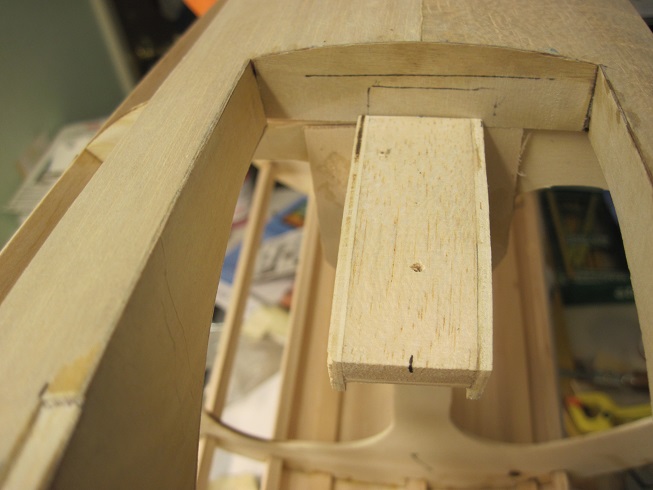
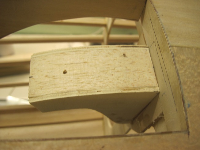
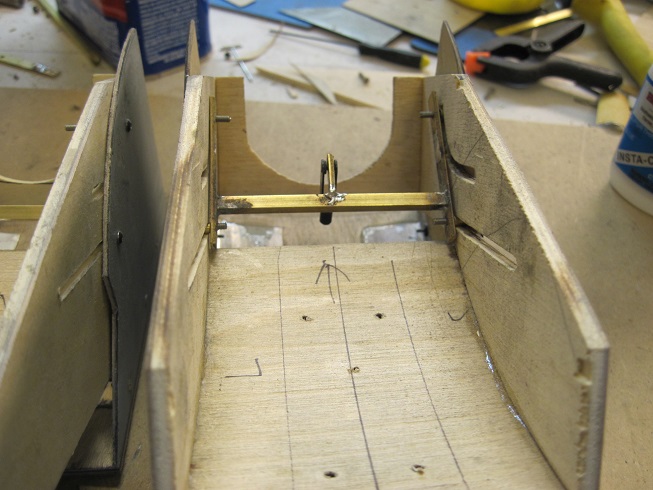
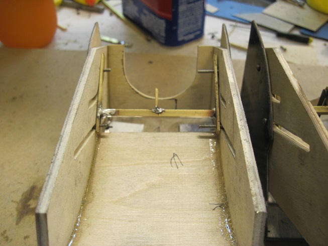
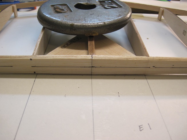
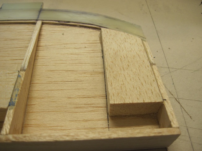
I set my fuel tray in between F2 and F3. I use the side saddle tank system and two 16oz tanks.
The tray is removable for now and may get glued in later. There will be a bit of g force on it as the tanks hang when the plane is upright. I have used this before so not worried, but probably will glue it in.
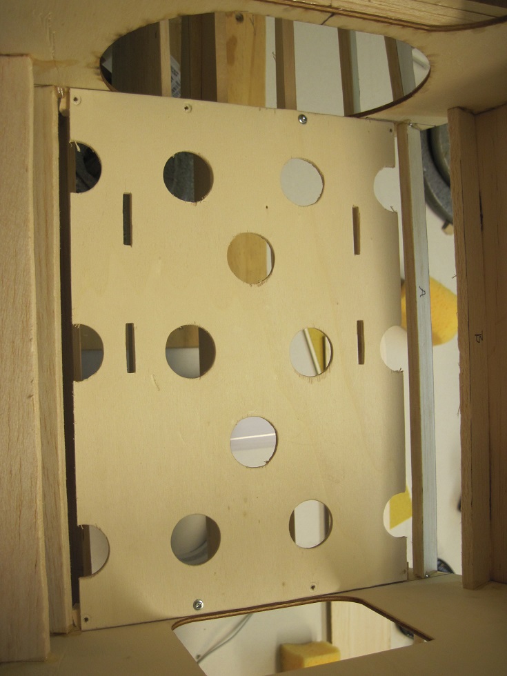
So fare the only thing missing from my kit is the F123 center stringer. This is 1/4" balsa for the noes profile. also missing was F123 "a" and F123 "b" both 1/4" balsa.
I just ended up going to the HS and got some 1/4" balsa sheets and cut them myself. I made the center F123 out of base wood as I wanted the strength at the spine.
I added a few extra stringers to the top.
Not sure why there is a set back notch in the firewall? My guess is they want you to use a thinner balsa sheet to round over on the top. Guess I will have to read the instructions")
FS3 is glued in and ready for the inner cooler door layups.
I will make the doors before I glue in FS2 and FS 4
TB
I set my fuel tray in between F2 and F3. I use the side saddle tank system and two 16oz tanks.
The tray is removable for now and may get glued in later. There will be a bit of g force on it as the tanks hang when the plane is upright. I have used this before so not worried, but probably will glue it in.
So fare the only thing missing from my kit is the F123 center stringer. This is 1/4" balsa for the noes profile. also missing was F123 "a" and F123 "b" both 1/4" balsa.
I just ended up going to the HS and got some 1/4" balsa sheets and cut them myself. I made the center F123 out of base wood as I wanted the strength at the spine.
I added a few extra stringers to the top.
Not sure why there is a set back notch in the firewall? My guess is they want you to use a thinner balsa sheet to round over on the top. Guess I will have to read the instructions
FS3 is glued in and ready for the inner cooler door layups.
I will make the doors before I glue in FS2 and FS 4
TB
08-24-2015, 09:11 AM
#80

My Feedback: (6)
Hay T/B
I like your tank plan, but I question having that much weight about 3 1/4 lbs. fwd of the C/G unless I am missing something, maybe a couple of the jet guys saddle tanks in the belly pan at the C/G and yea tat makes for long lines but the engine you going to use should have no problems with them. I have also used the hanging tank platform and use rubber band to hold them in place, seams to work well and easy removal.
PS Please post a side view of the whole fuse, then I wont need to upset you build.
Cheers Bob T
08-24-2015, 09:17 AM
#81
Bob, my tanks are at the CG, most push the tank all the way forward but I like it over the CG so it does not change much in flight.
I use velcro to keep the tanks from sliding around and HD Velcro straps securing the tanks to the tray, they are not going anywhere.
TB
I use velcro to keep the tanks from sliding around and HD Velcro straps securing the tanks to the tray, they are not going anywhere.
TB
 08-26-2015, 03:34 AM
#83
Progress.
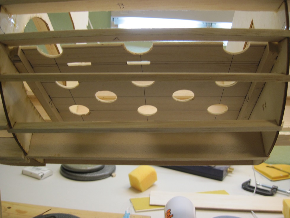
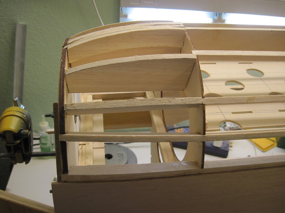
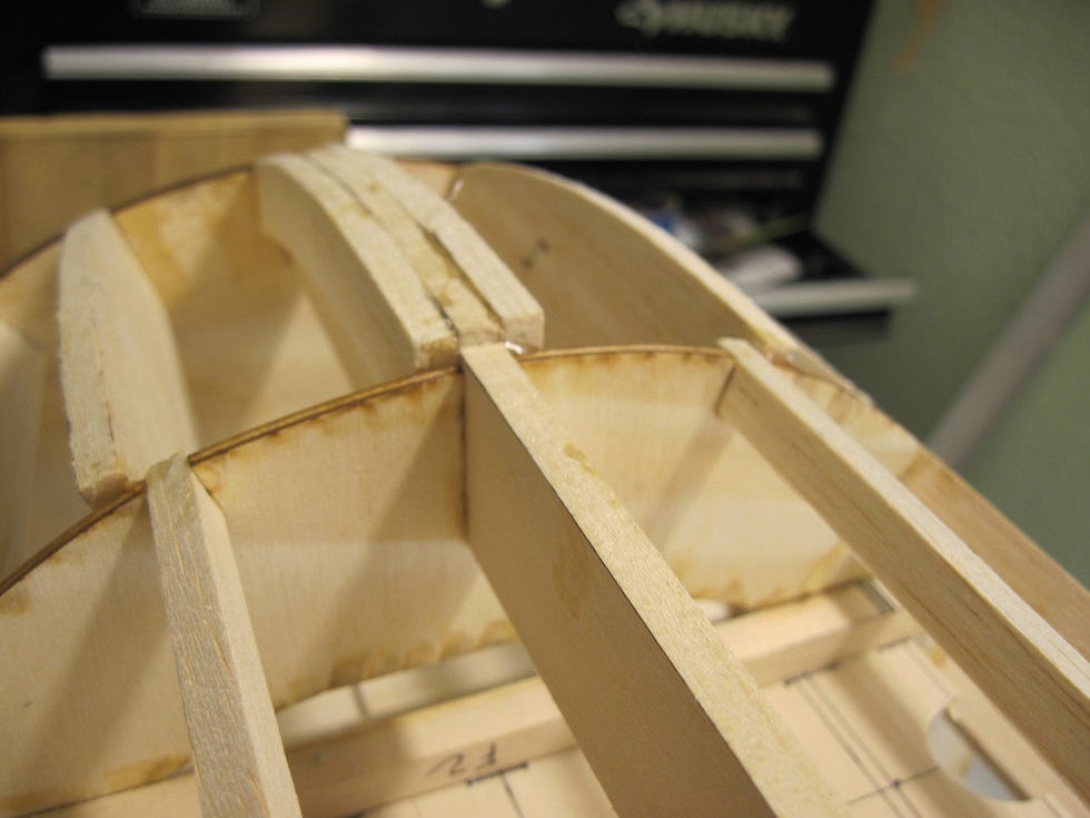
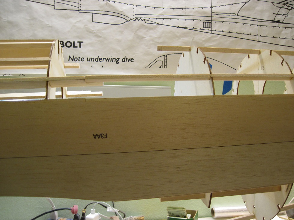
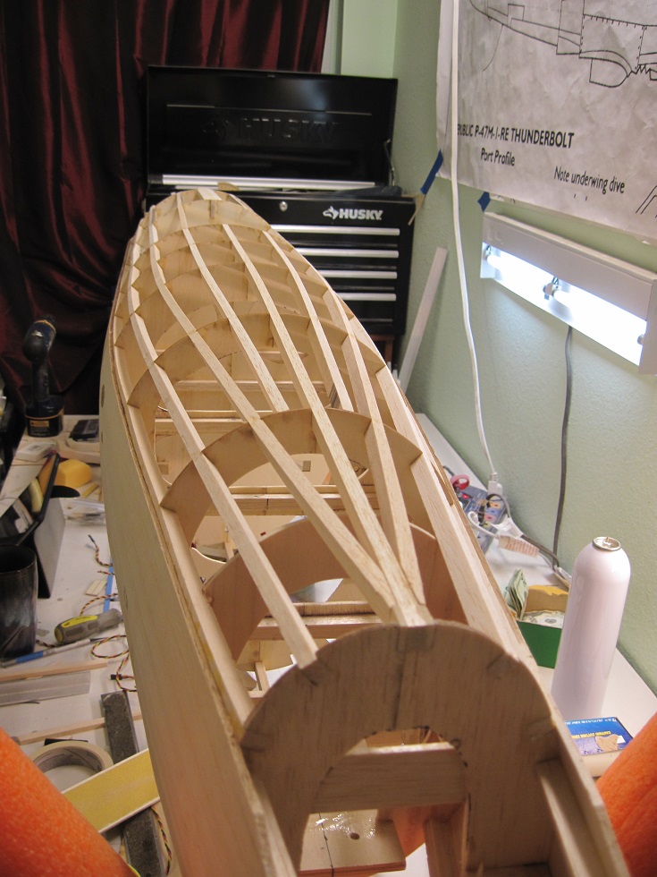
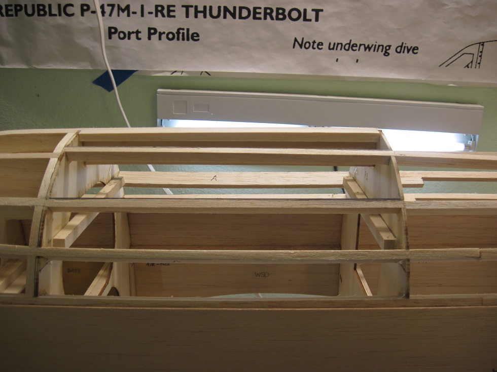
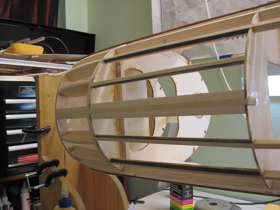
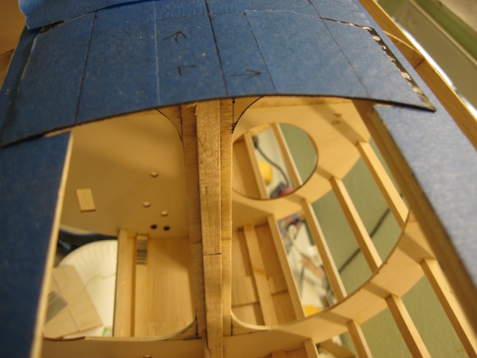
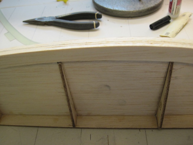
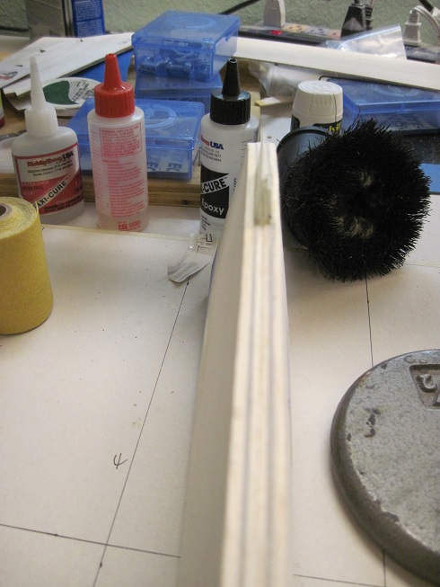
All the stringers are installed on the top half of the fuselage.
I sanded the front stringers that make up the tapered noes.
One reason I used base wood on the spine top stringer F-123 is to give strength if when I put the plane in a cradle upside down.
This area is subject to stress and can crack.
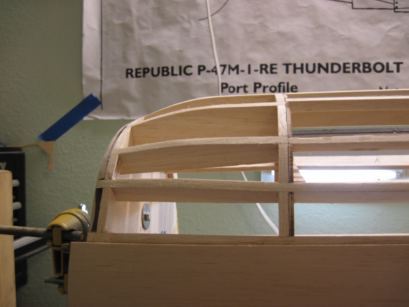
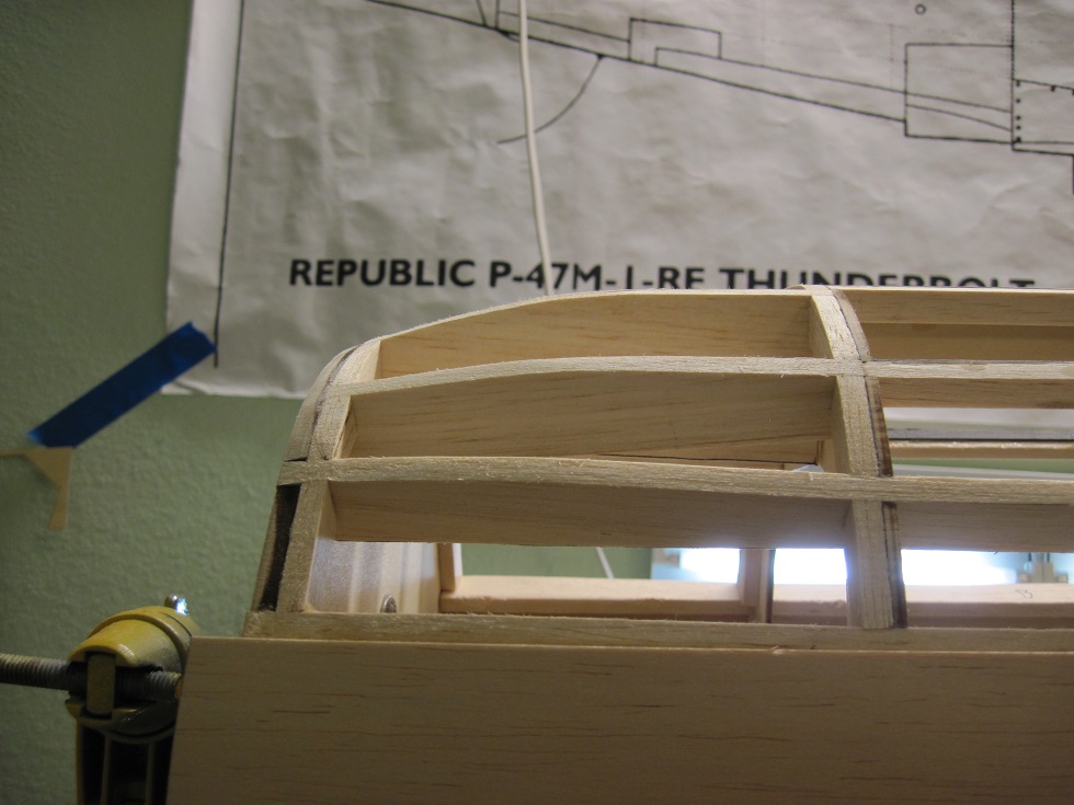
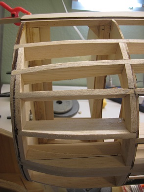
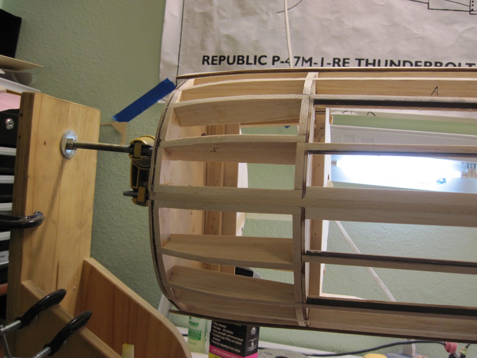
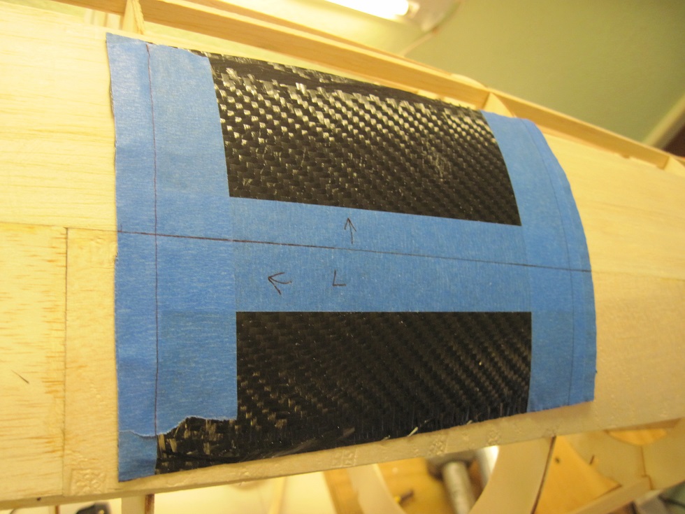
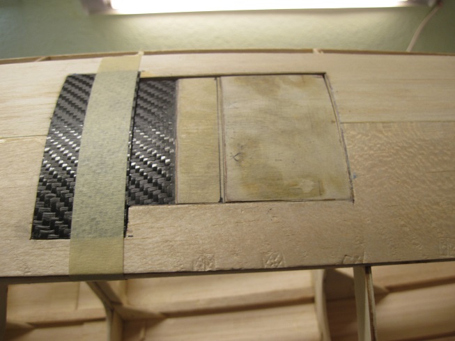
On the balsa top four stringers from F-2 to F-3 I added some carbon fiber strips to stiffen these up. This is a weak area in my opinion so the added strength is needed
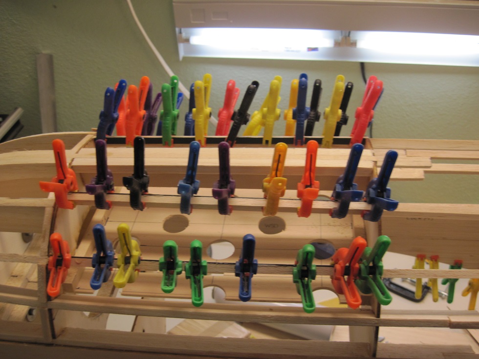
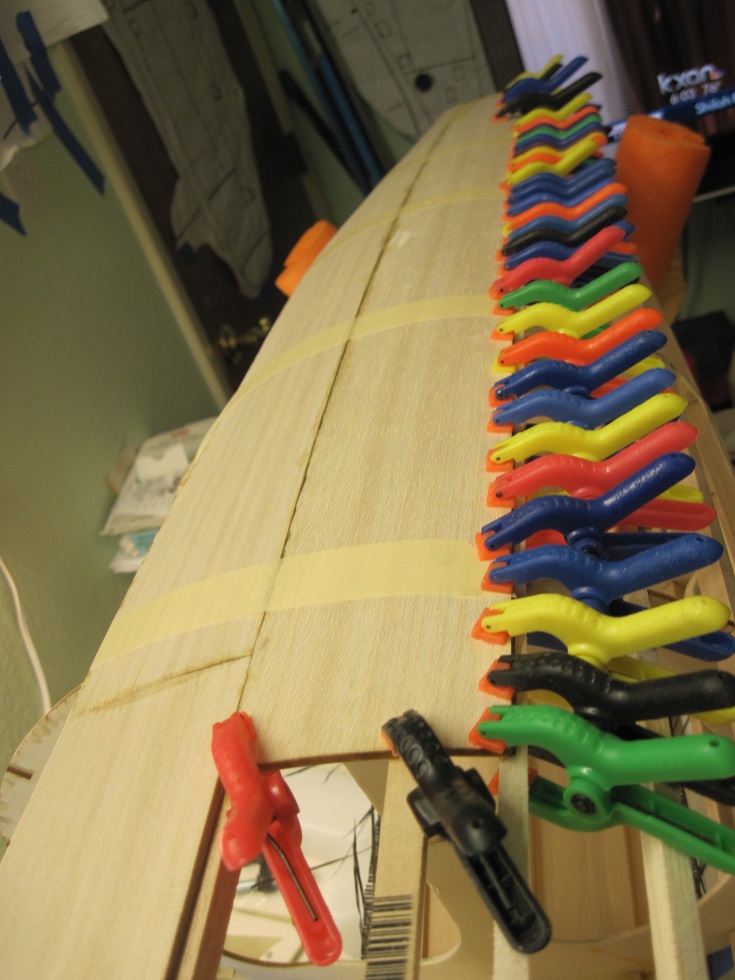
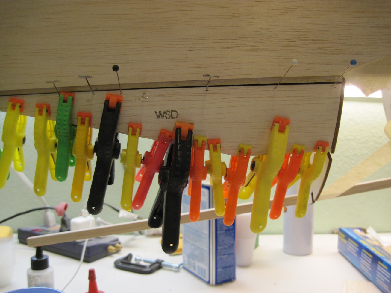
Both sides have the sheeting FS 1and FS 1a, FS 3 and FS 3a glued in, along with the two WSD.
This is all I will do until all the push rods are in and the inner cooler doors are installed.
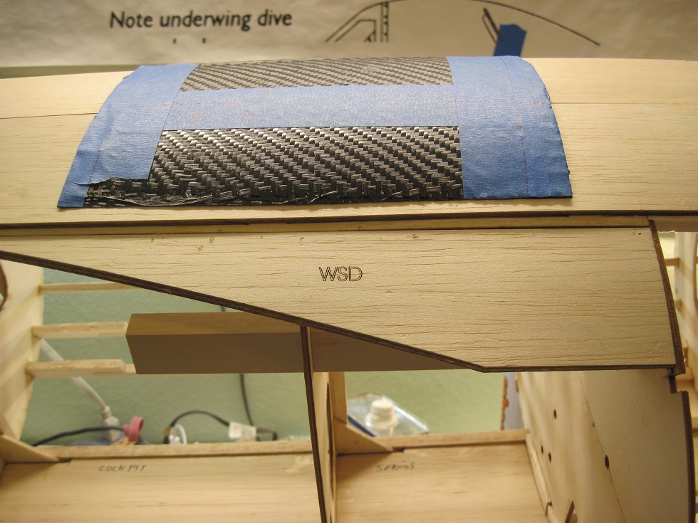
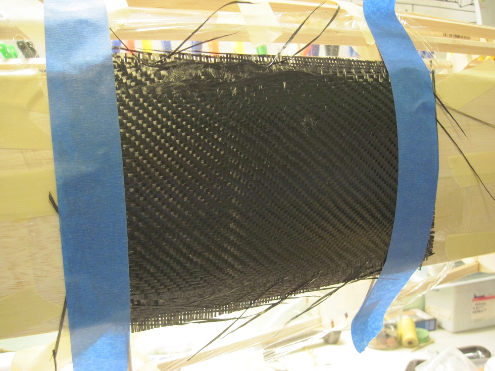
Both carbon fiber inner cooler door layups are laid and curing.
I will cut them and back them with 1/32 birch ply. This will lock them in.
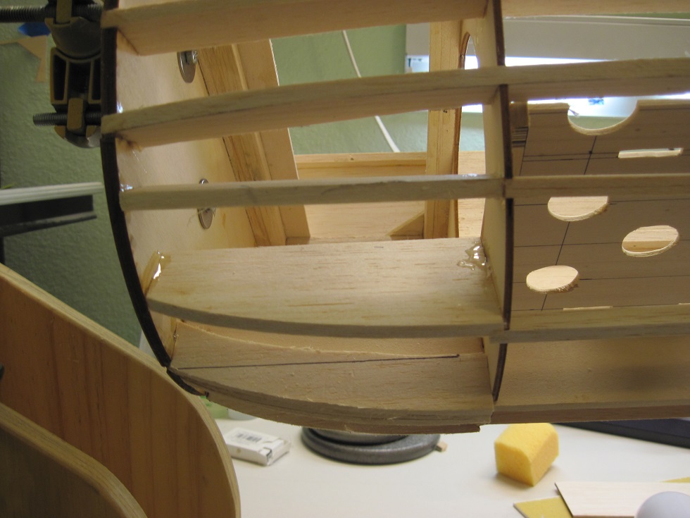
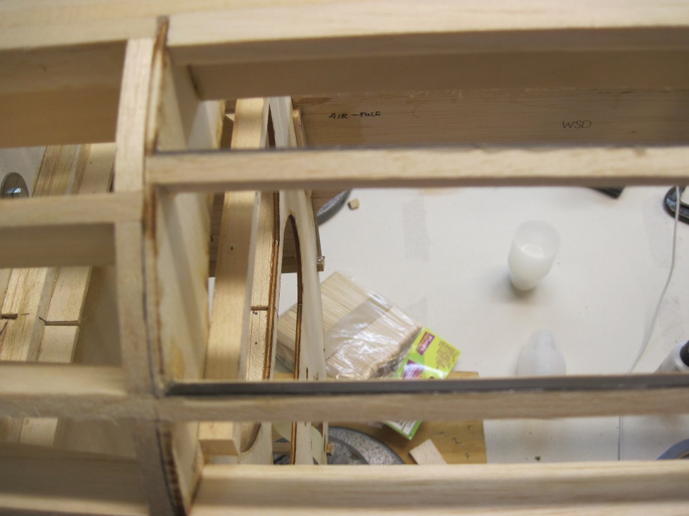
The frount underside chine gets base wood stringers for strength, this area will end up with a carbon fiber skin that will house the exhaust exits.
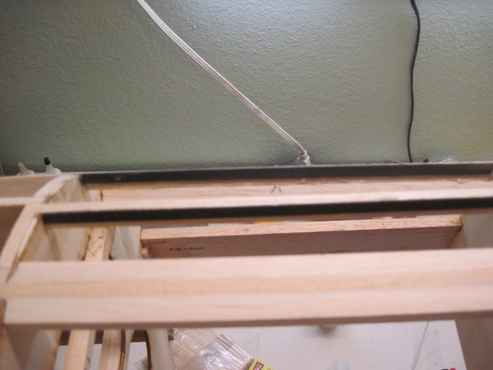
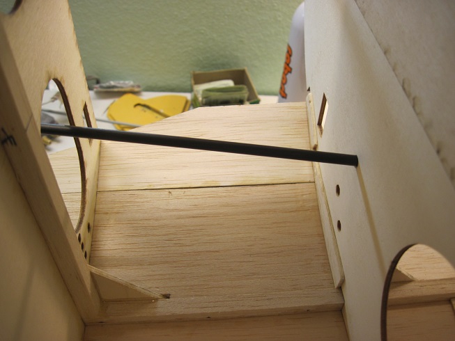
The servo tray for the elevator and rudder is just behind F4 and between F5. this location allows for the pushrod to be high in the top of the fuselage to clear the tail wheel when retracted.
It also gives a strait shot for the pull pull on the ruder and steering.
Onward.
TB
All the stringers are installed on the top half of the fuselage.
I sanded the front stringers that make up the tapered noes.
One reason I used base wood on the spine top stringer F-123 is to give strength if when I put the plane in a cradle upside down.
This area is subject to stress and can crack.
On the balsa top four stringers from F-2 to F-3 I added some carbon fiber strips to stiffen these up. This is a weak area in my opinion so the added strength is needed
Both sides have the sheeting FS 1and FS 1a, FS 3 and FS 3a glued in, along with the two WSD.
This is all I will do until all the push rods are in and the inner cooler doors are installed.
Both carbon fiber inner cooler door layups are laid and curing.
I will cut them and back them with 1/32 birch ply. This will lock them in.
The frount underside chine gets base wood stringers for strength, this area will end up with a carbon fiber skin that will house the exhaust exits.
The servo tray for the elevator and rudder is just behind F4 and between F5. this location allows for the pushrod to be high in the top of the fuselage to clear the tail wheel when retracted.
It also gives a strait shot for the pull pull on the ruder and steering.
Onward.
TB
08-27-2015, 12:57 PM
#84
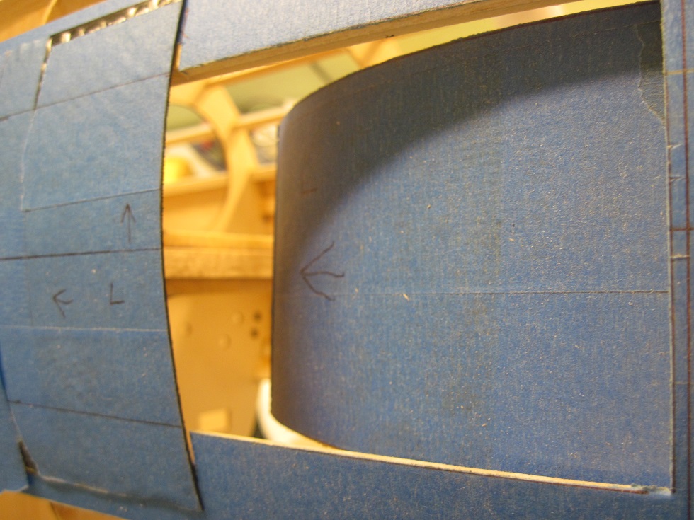
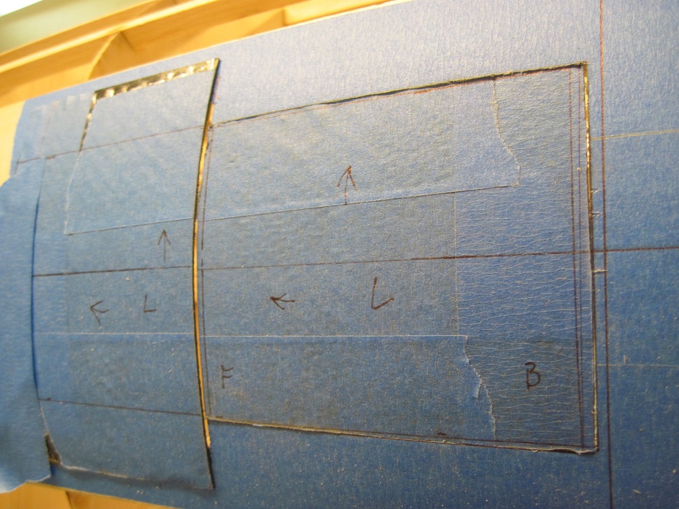
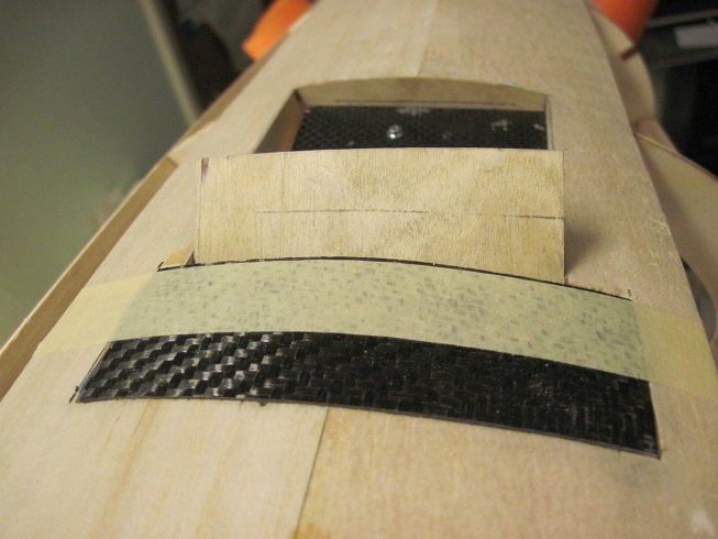
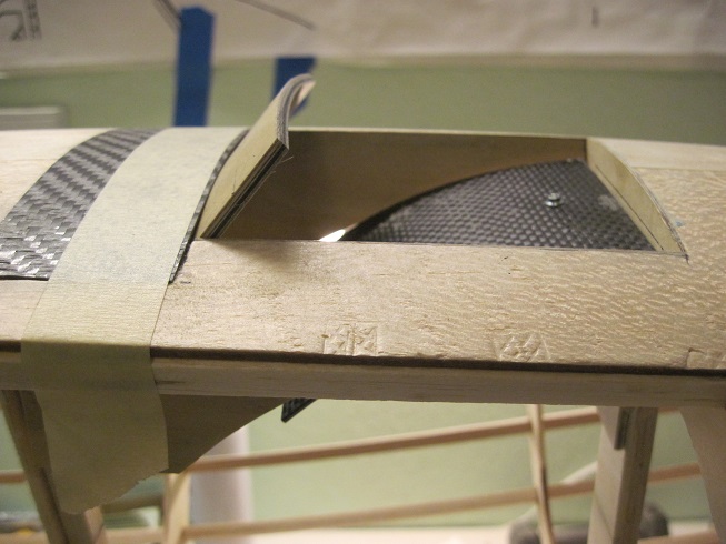
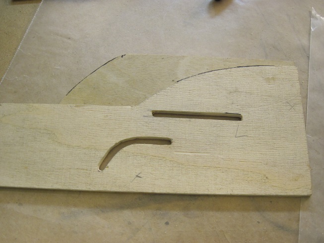
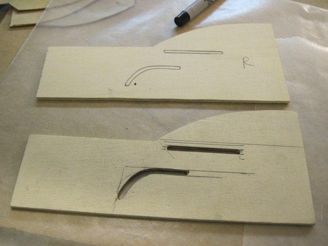
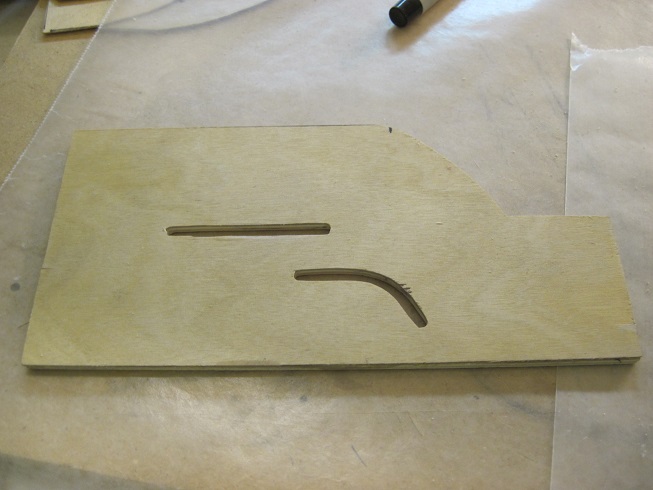
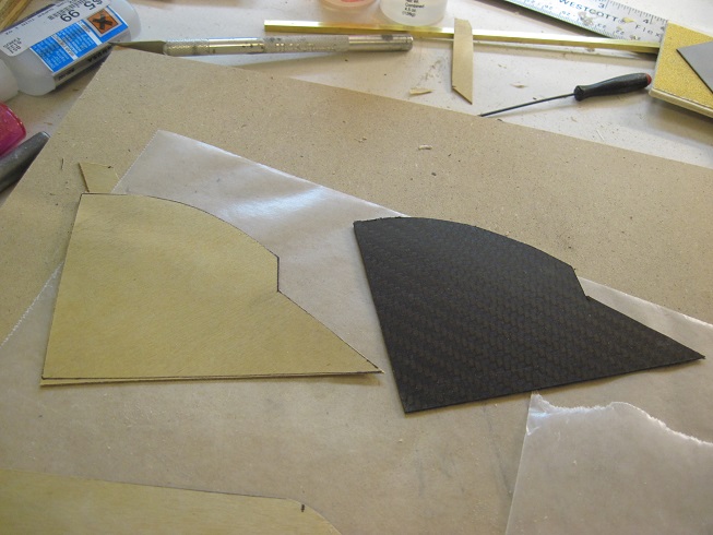
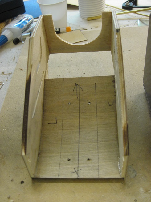
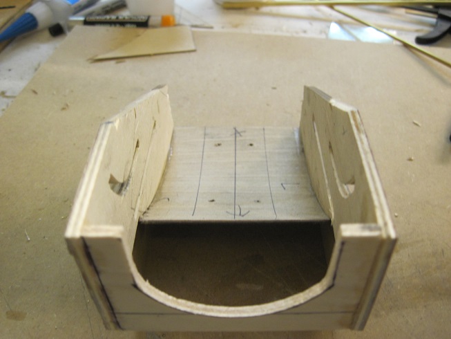
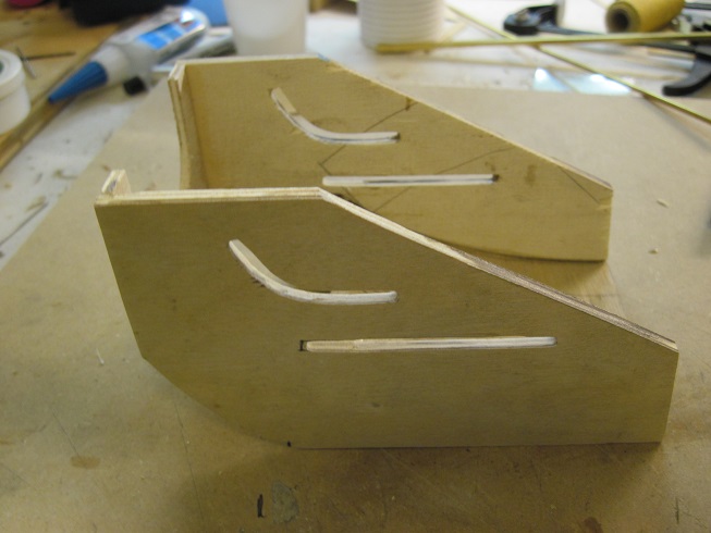
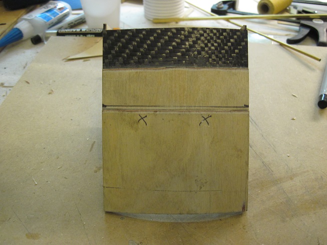
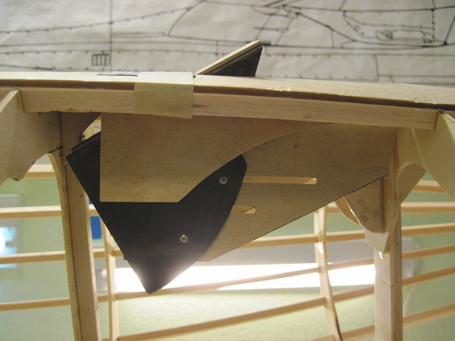
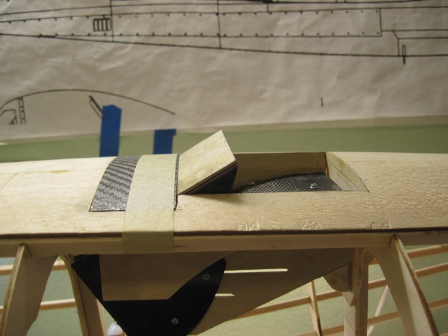
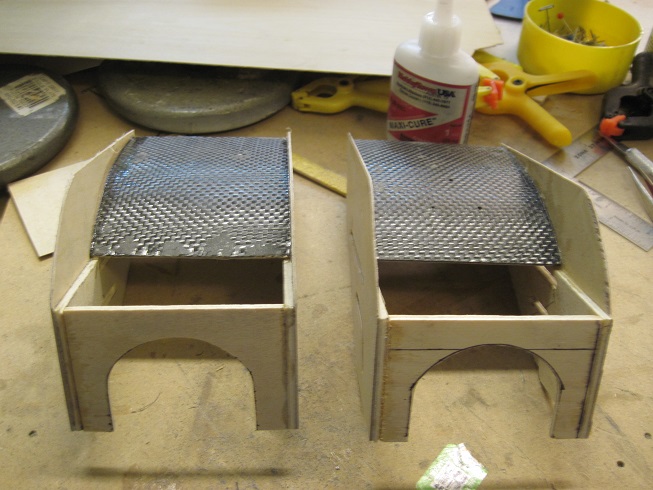
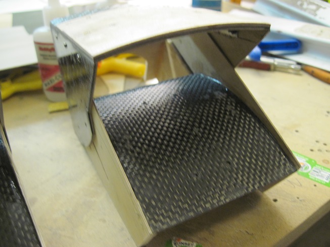
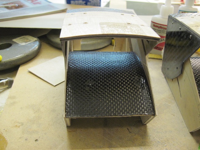
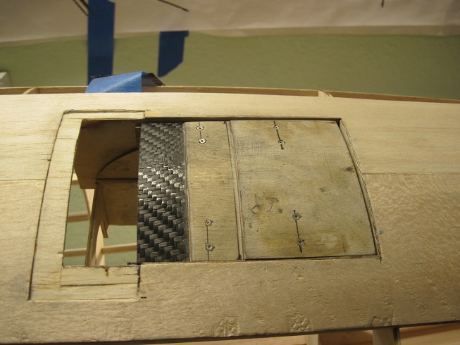
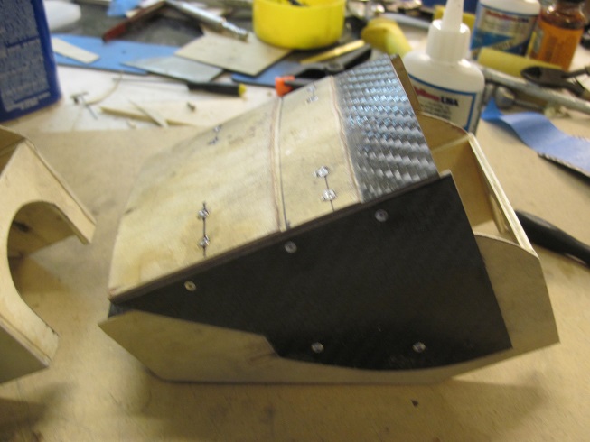
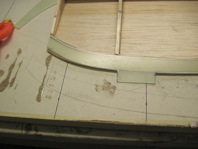
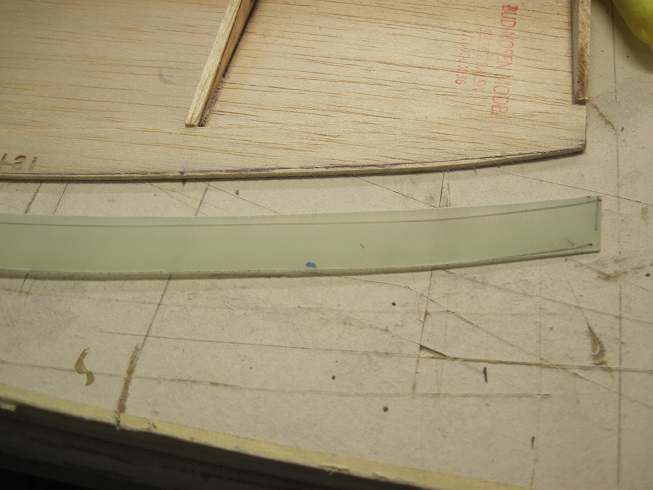
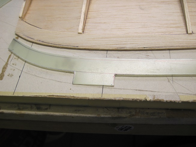
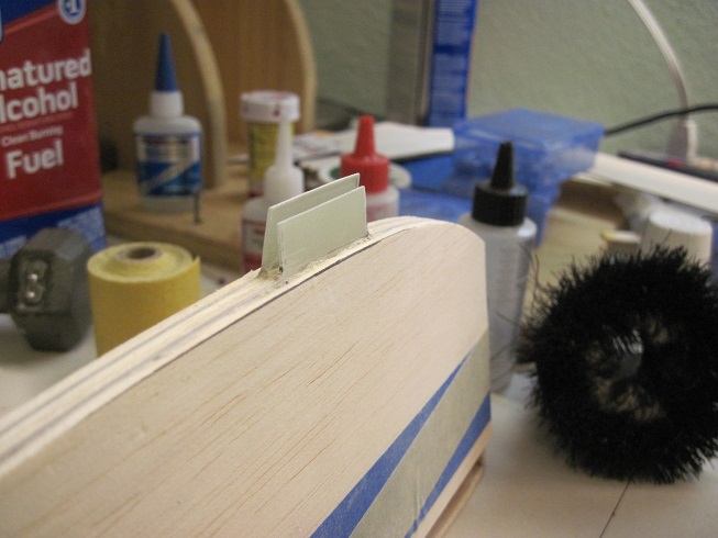
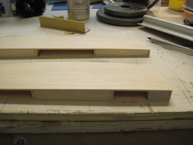
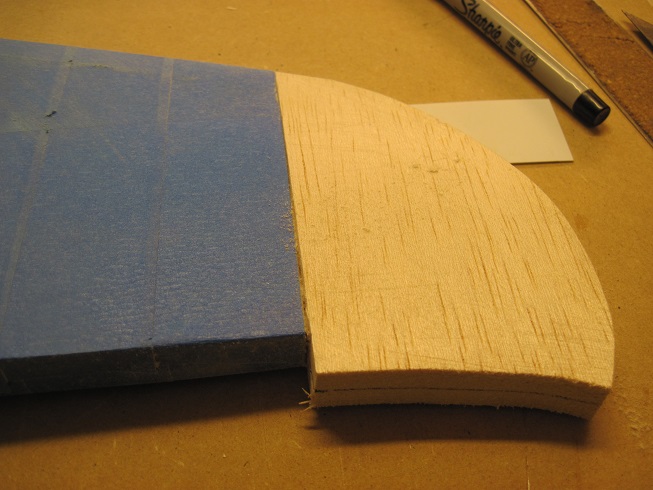
Got a start on the inner cooler doors.
The doors are going to be maid from three pieces.
One is the door itself.
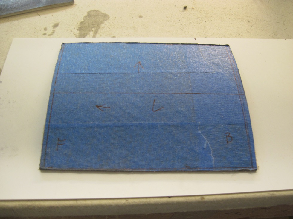
It has a piece of 1/32" birch ply glued to the underside. This gives it a lot of rigidity.
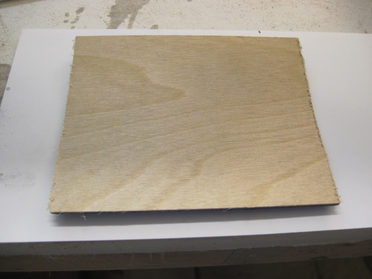
The second piece is the inside bottom that houses the door and will have the track on it. this gets attached to the inside of the fuselage.
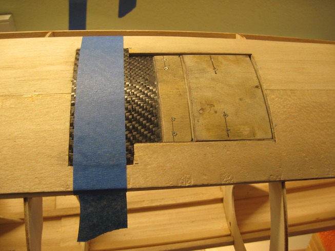
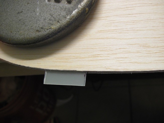
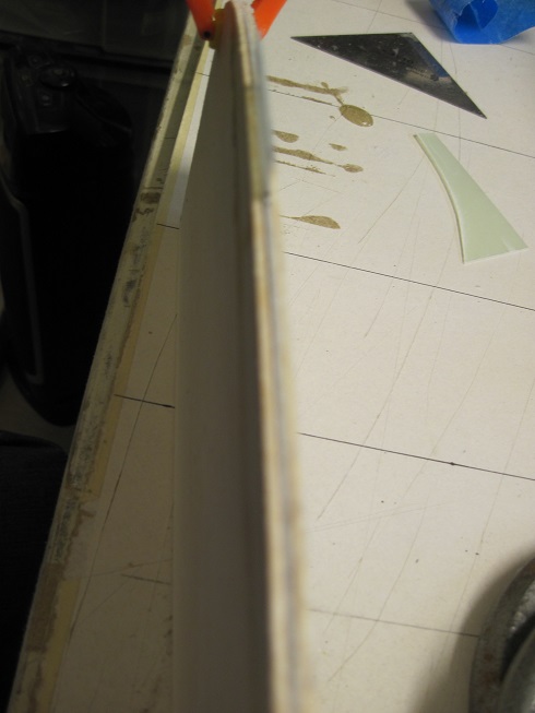
The third piece is the skin that is just in front of the door as this area needs to be thin and strong. This skin will get glued in and flush out with the fuselage skin.
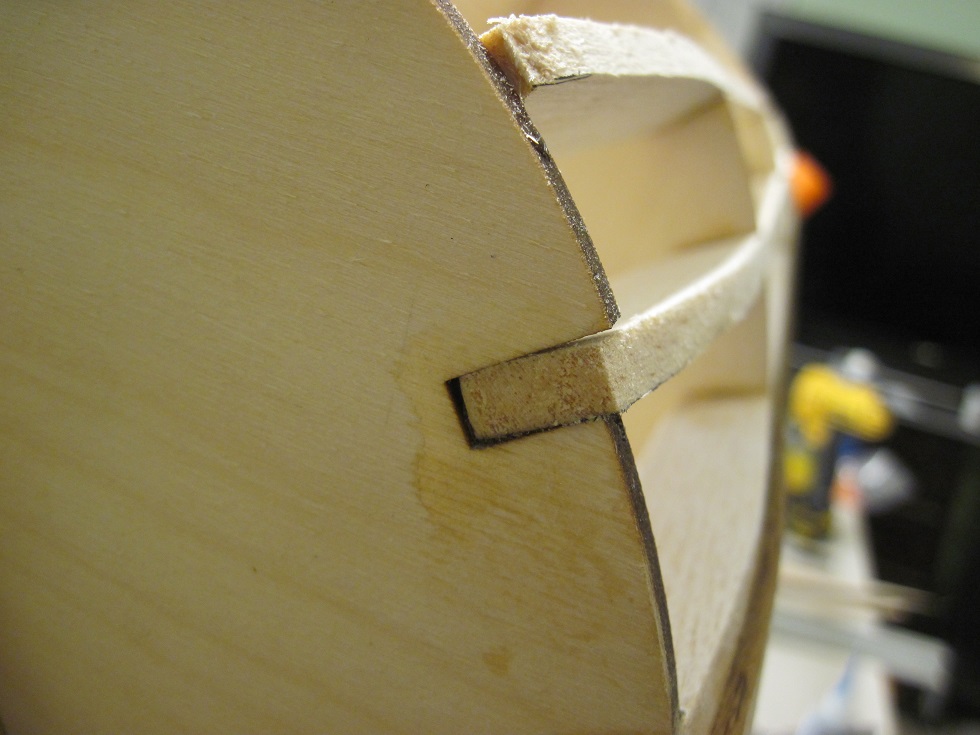
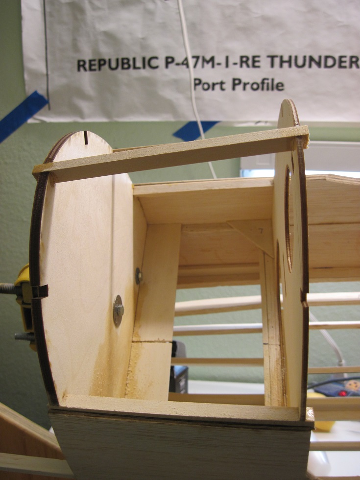
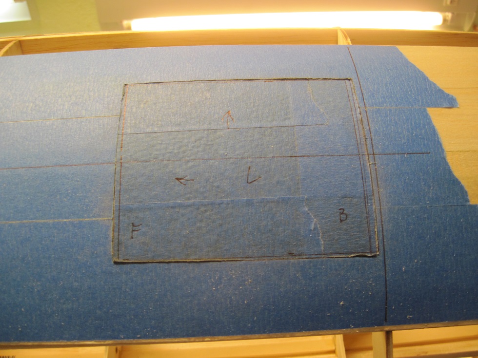
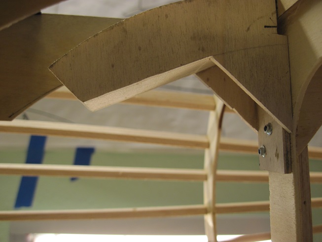
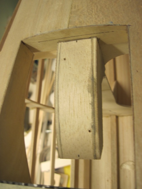
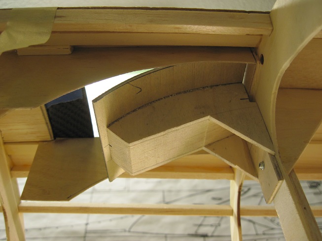
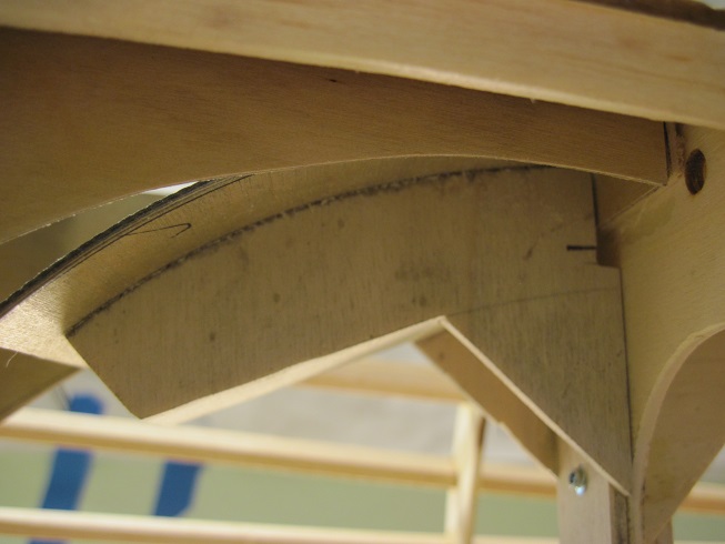
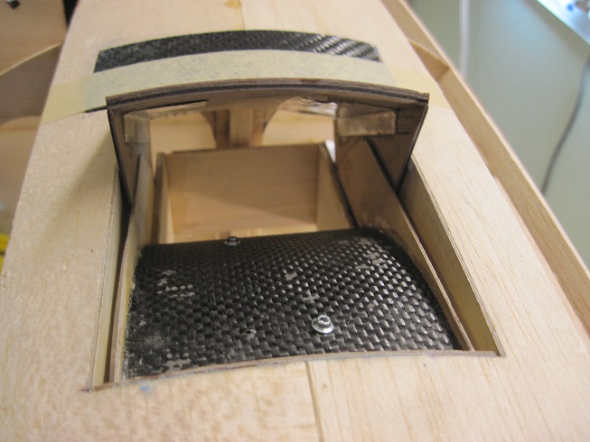
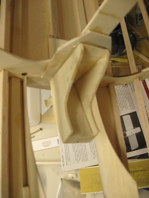
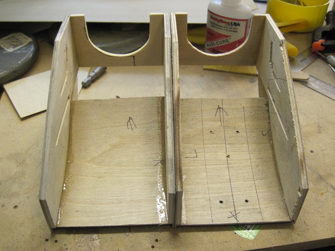
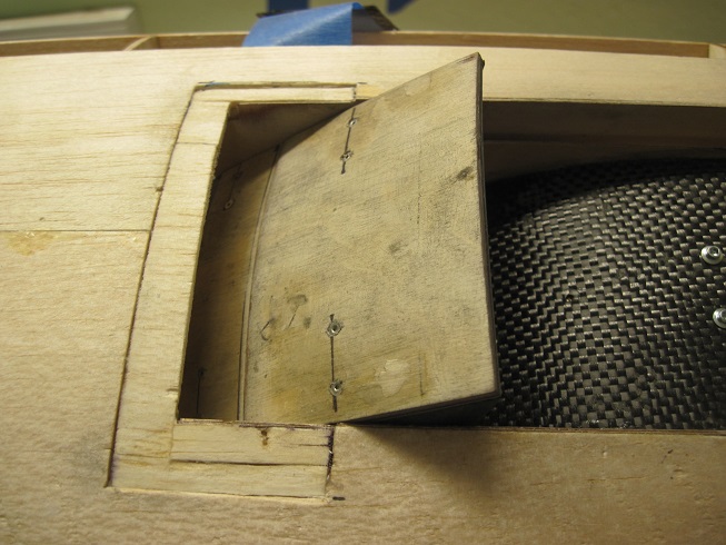
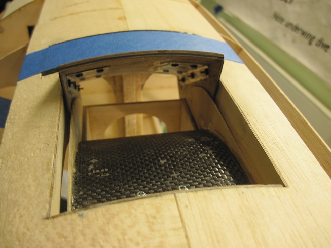
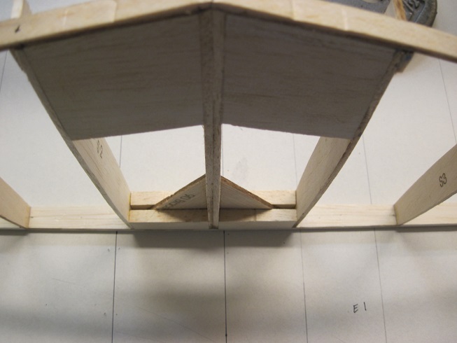
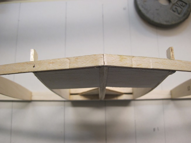
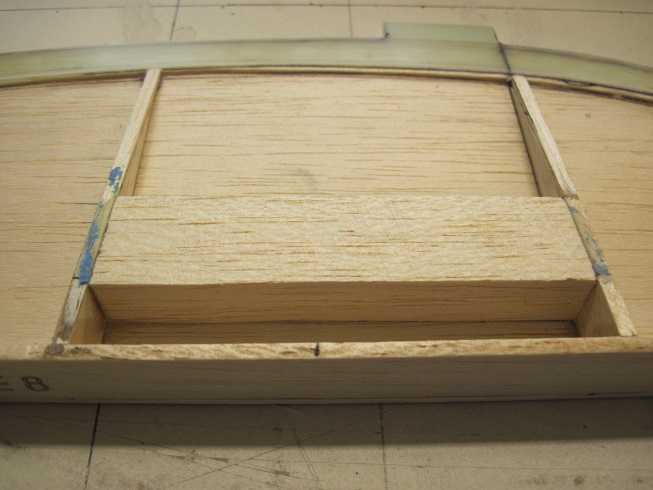
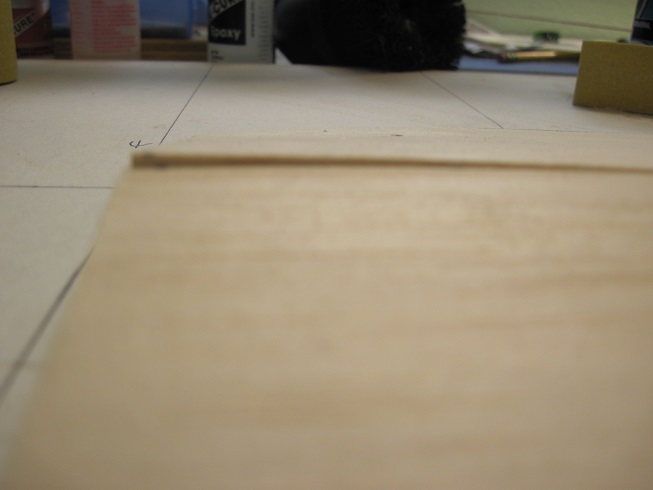
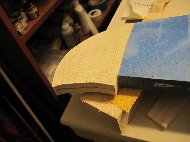
The opening is cut out and the two base wood stringers help keep it all together as I cut out the center crutch.
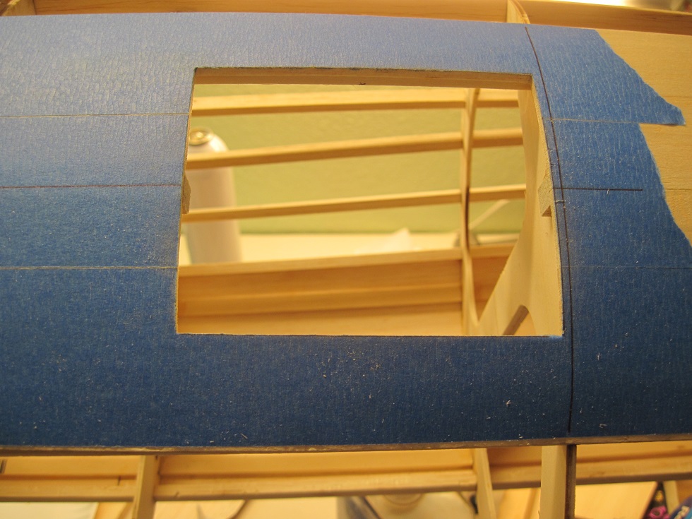
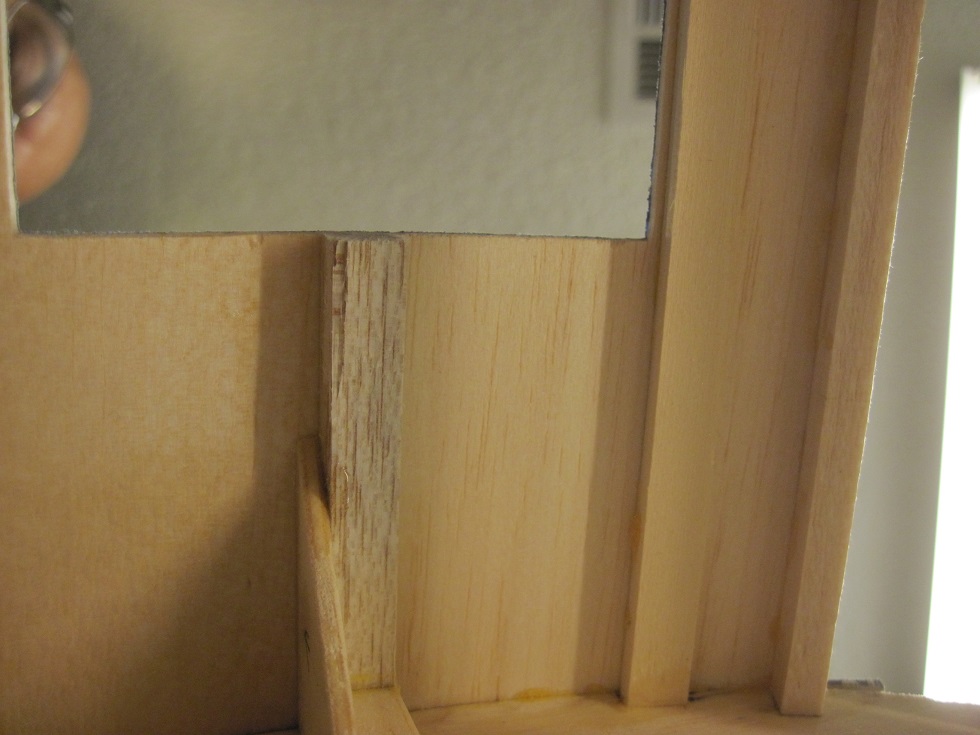
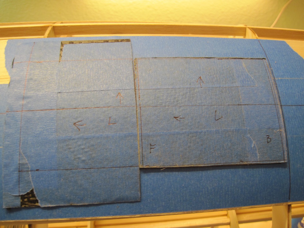
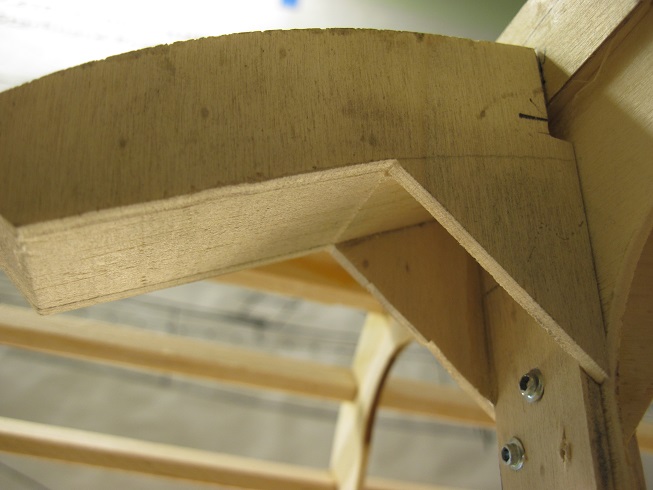
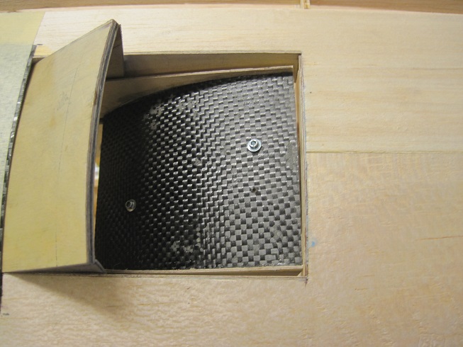
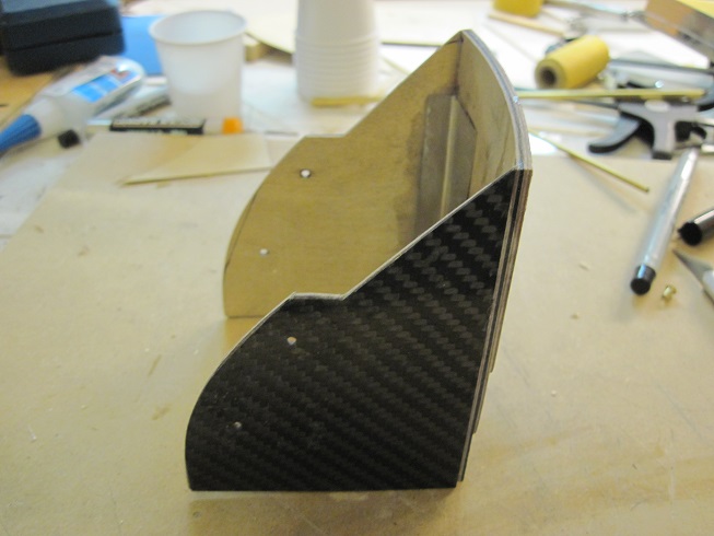
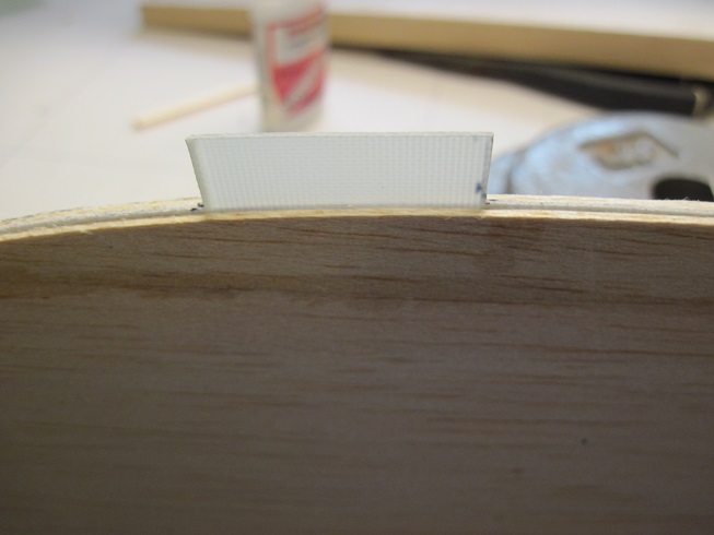
This is what the inside bottom piece will look like but with sides. This gets mounted to F7
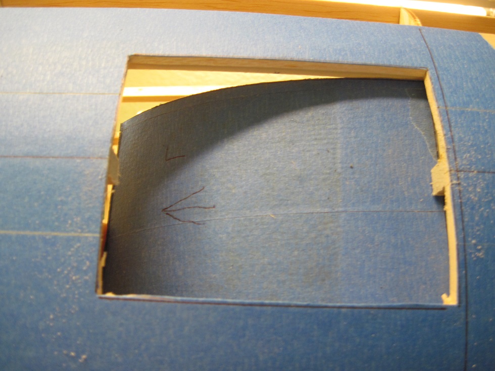
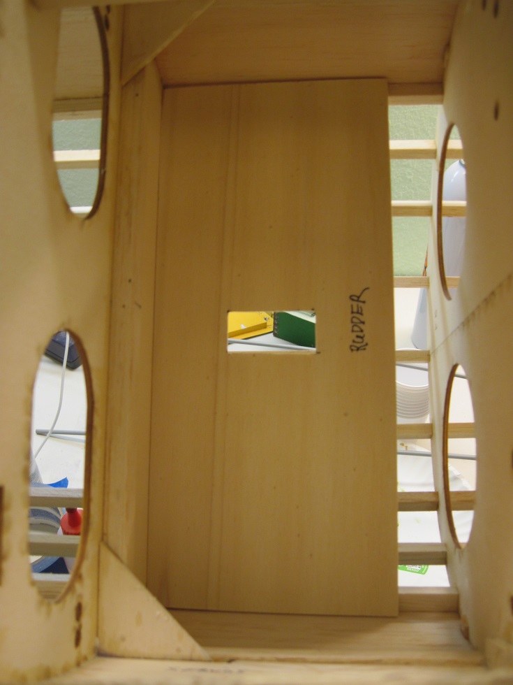
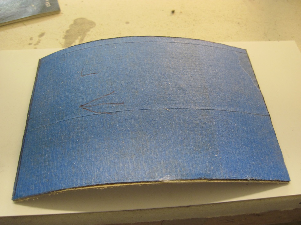
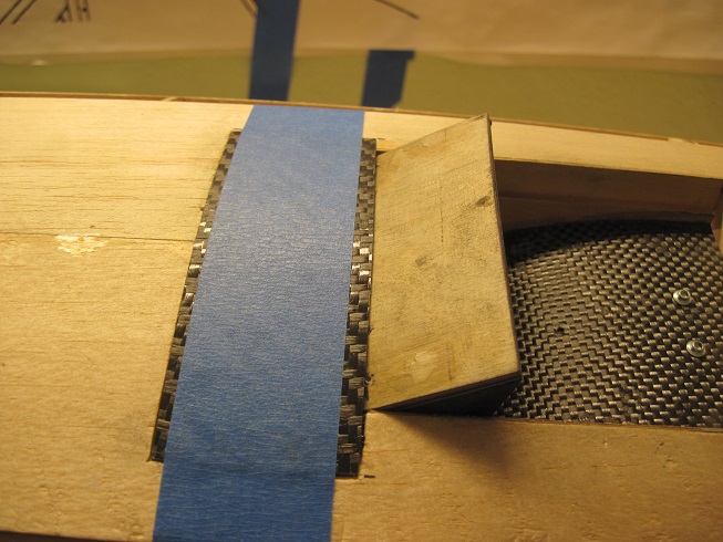
The skin is in front to the door just behind F6.
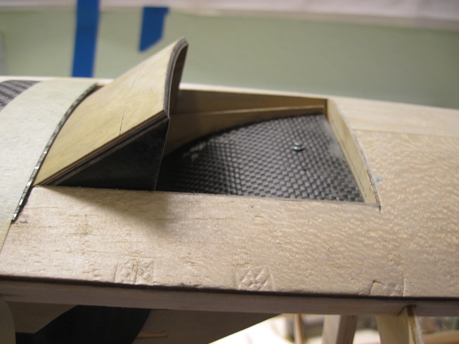
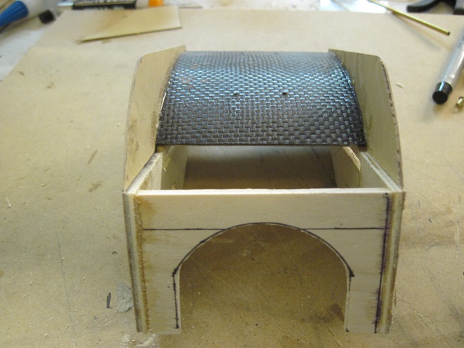
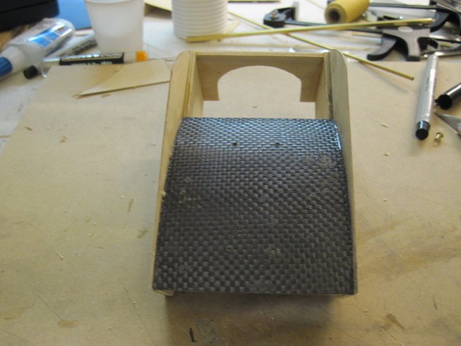
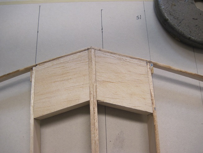
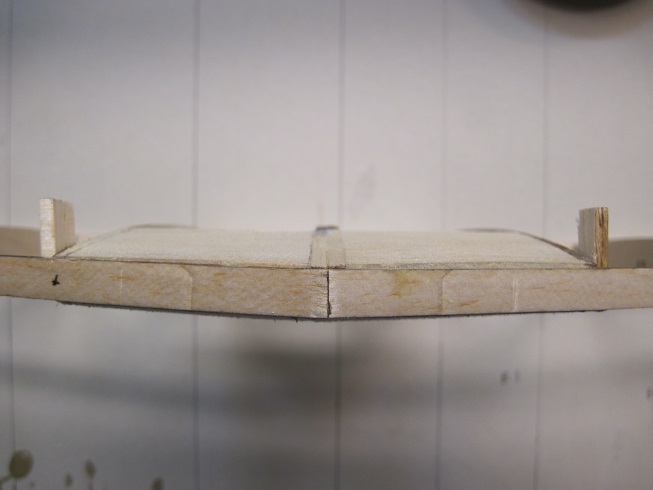
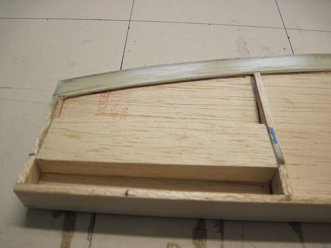
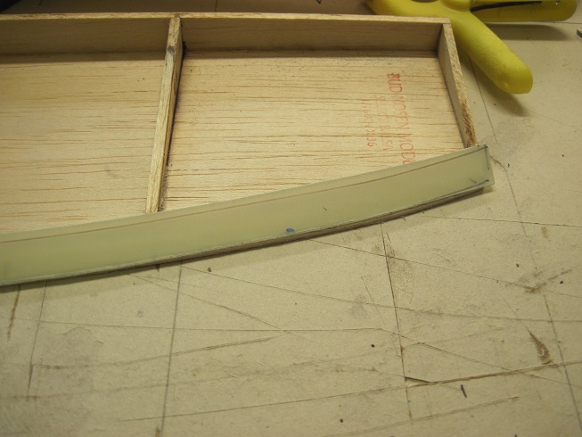
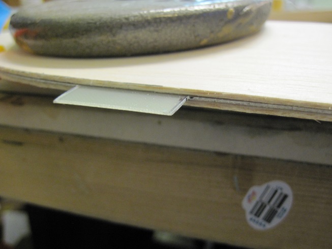
This is kind of what the door looks like closed. but it is not finished, just a dry fit.
I will work on the sled and the rest later this week.
TB
The doors are going to be maid from three pieces.
One is the door itself.
It has a piece of 1/32" birch ply glued to the underside. This gives it a lot of rigidity.
The second piece is the inside bottom that houses the door and will have the track on it. this gets attached to the inside of the fuselage.
The third piece is the skin that is just in front of the door as this area needs to be thin and strong. This skin will get glued in and flush out with the fuselage skin.
The opening is cut out and the two base wood stringers help keep it all together as I cut out the center crutch.
This is what the inside bottom piece will look like but with sides. This gets mounted to F7
The skin is in front to the door just behind F6.
This is kind of what the door looks like closed. but it is not finished, just a dry fit.
I will work on the sled and the rest later this week.
TB
08-30-2015, 05:46 AM
#85
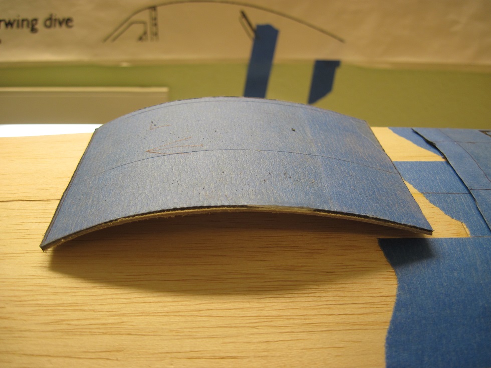
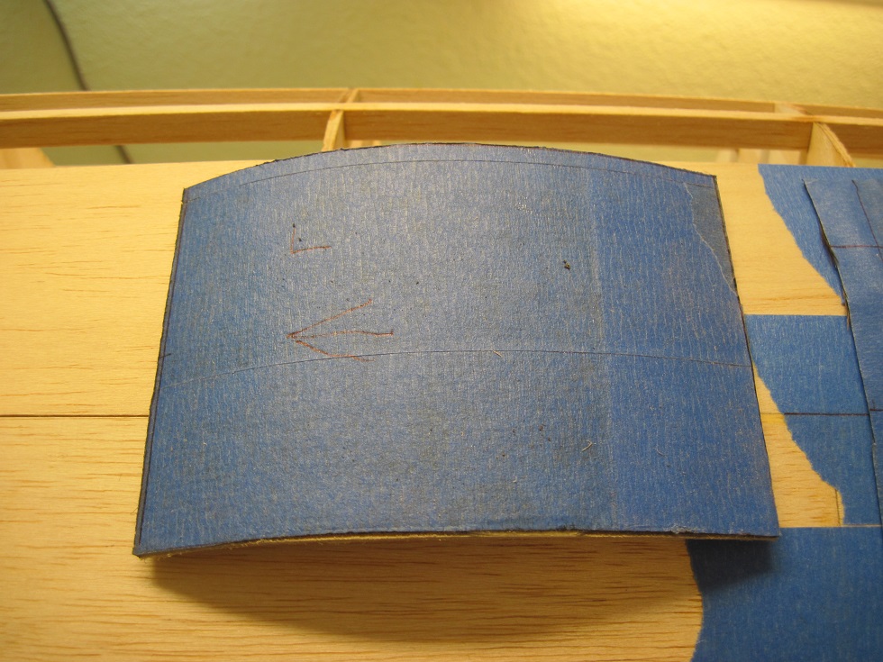
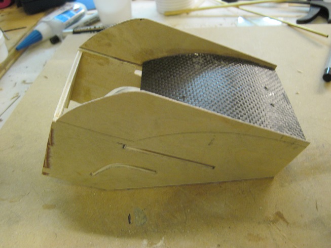
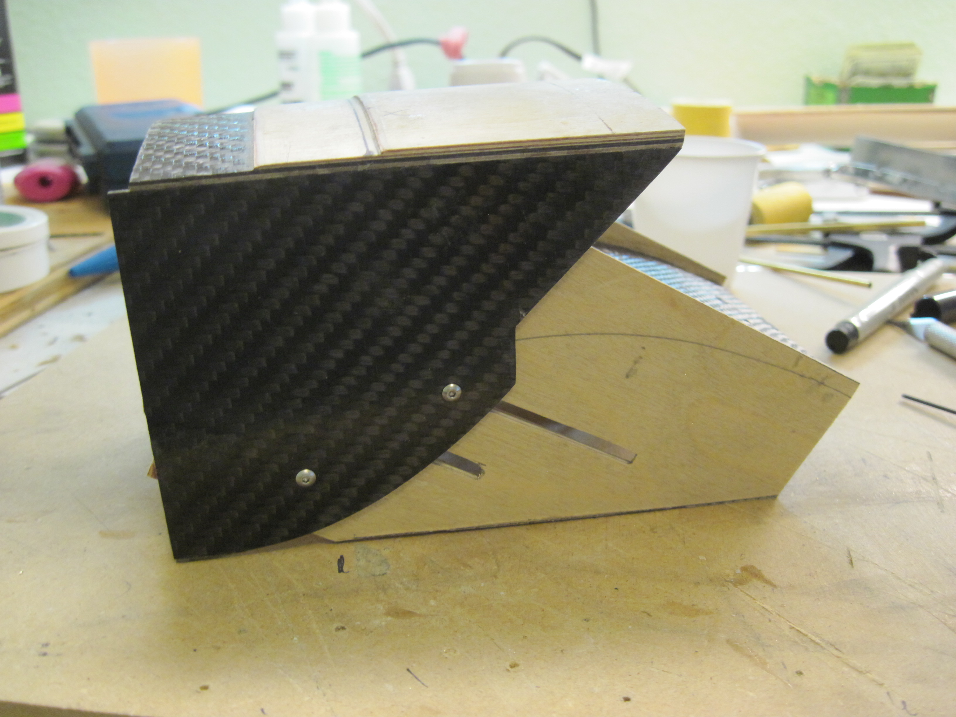
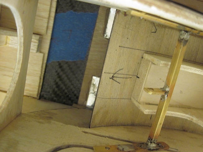
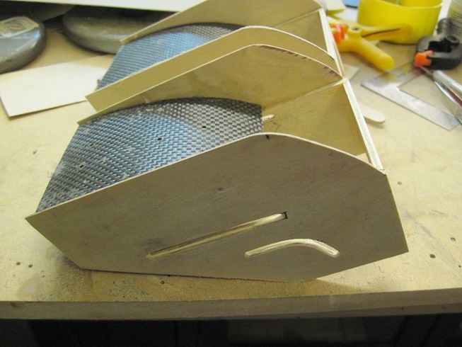
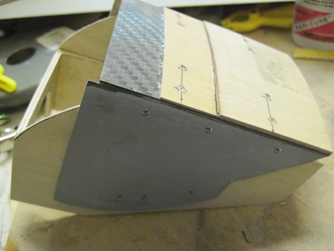
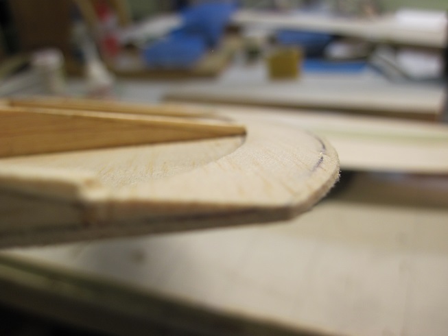
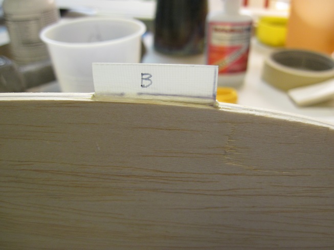
Some progress on the inner cooler doors.
Figuring out how it all works takes time but I think I got it.
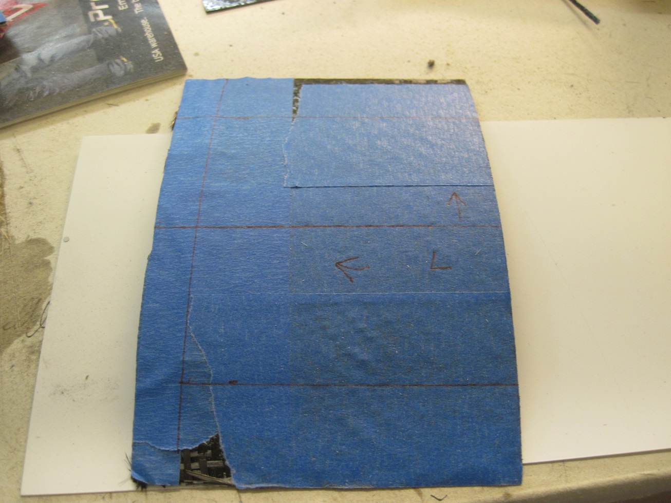
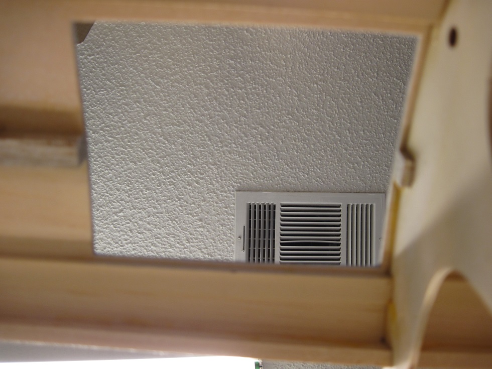
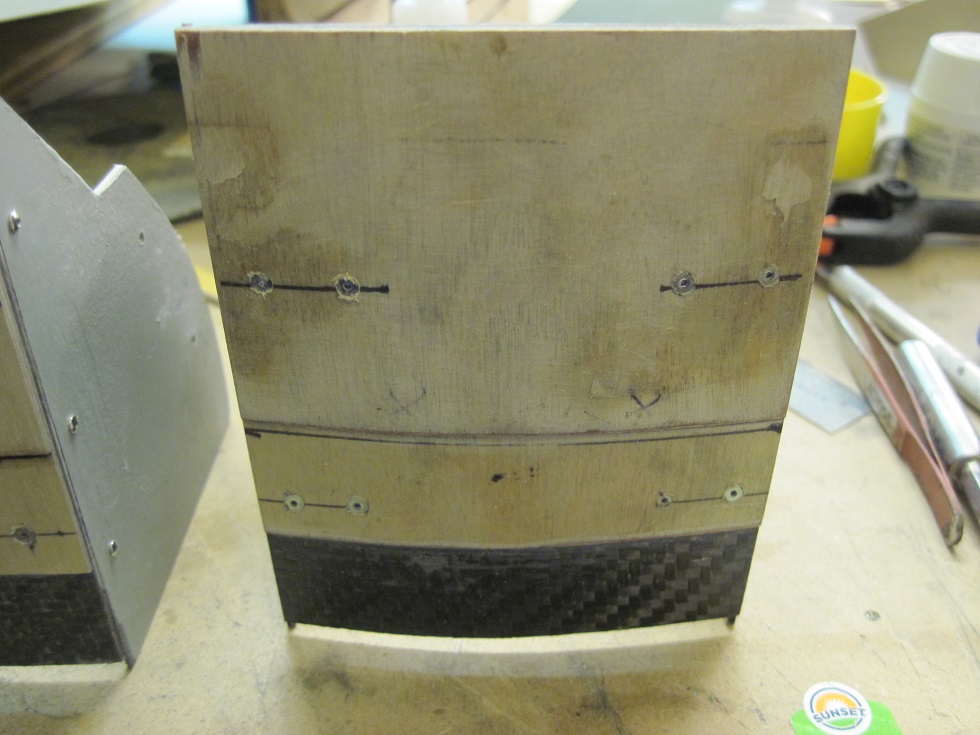
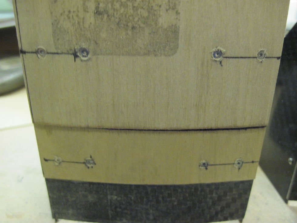
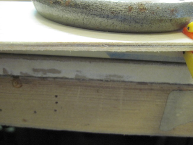
This is the finished layered door. The rear 2/3 is flush with the fuselage skin. The front 1/3 is stepped down so when it slides forward it is under the skin and then start to open up.
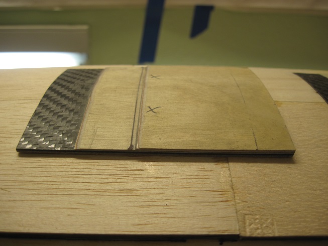
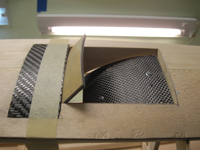
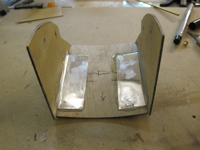
The base is what will hold the bottom housing of the door. This is just tacked for fitting and will get glued in.
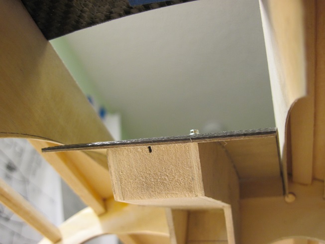
The bottom plate gets attached to the base bracket, this holds the door and slide mechanism.
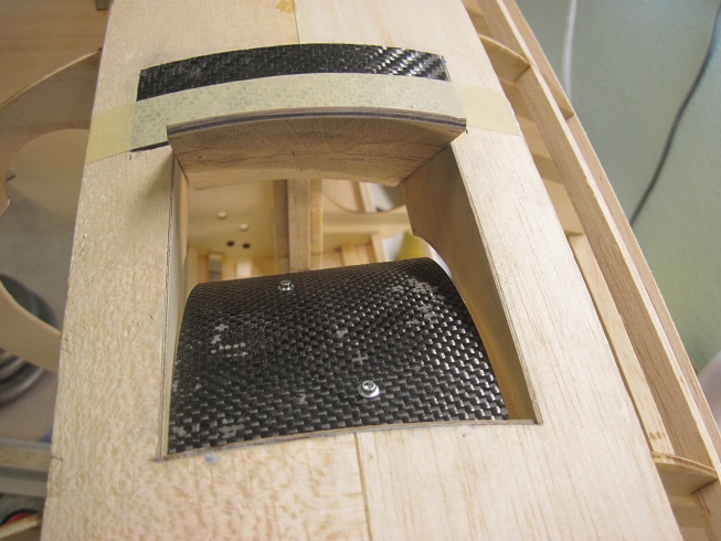
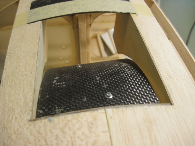
The sides of the bottom plate will have the groves in it and will be glued to the bottom plate.
The sides of the door are laminated carbon fiber laminates and 1/32 birch ply. These get glued to the doors as the sides.
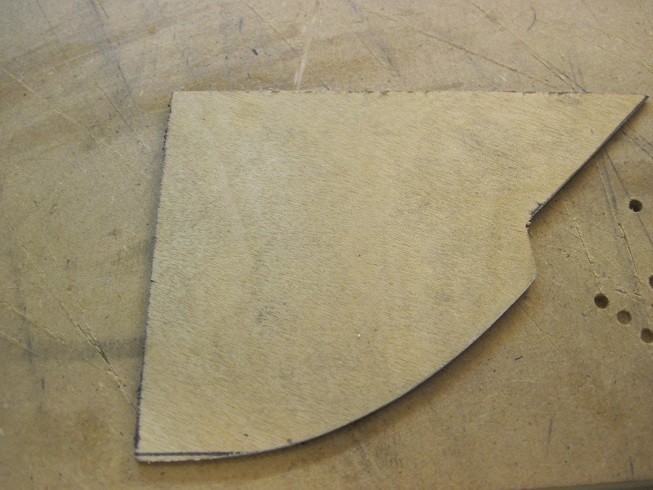
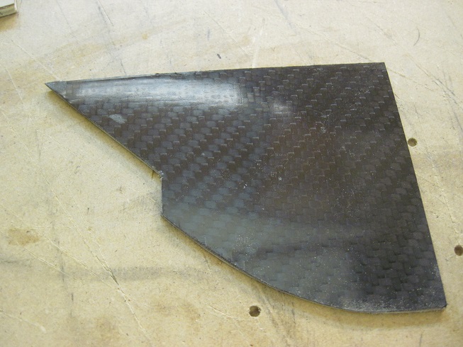
Still some fabricating to do but I am getting there.
TB
Figuring out how it all works takes time but I think I got it.
This is the finished layered door. The rear 2/3 is flush with the fuselage skin. The front 1/3 is stepped down so when it slides forward it is under the skin and then start to open up.
The base is what will hold the bottom housing of the door. This is just tacked for fitting and will get glued in.
The bottom plate gets attached to the base bracket, this holds the door and slide mechanism.
The sides of the bottom plate will have the groves in it and will be glued to the bottom plate.
The sides of the door are laminated carbon fiber laminates and 1/32 birch ply. These get glued to the doors as the sides.
Still some fabricating to do but I am getting there.
TB
08-30-2015, 03:04 PM
#87
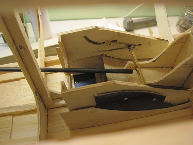
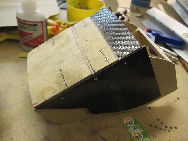
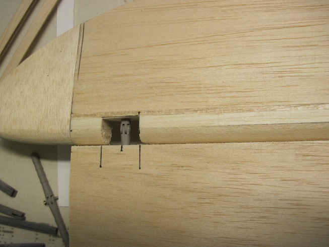
Progress.
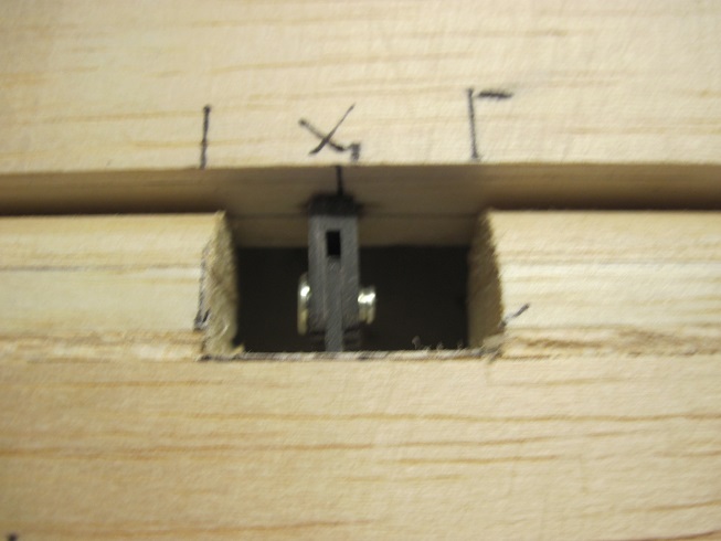
So the left door is done and being fitted for adjustments.
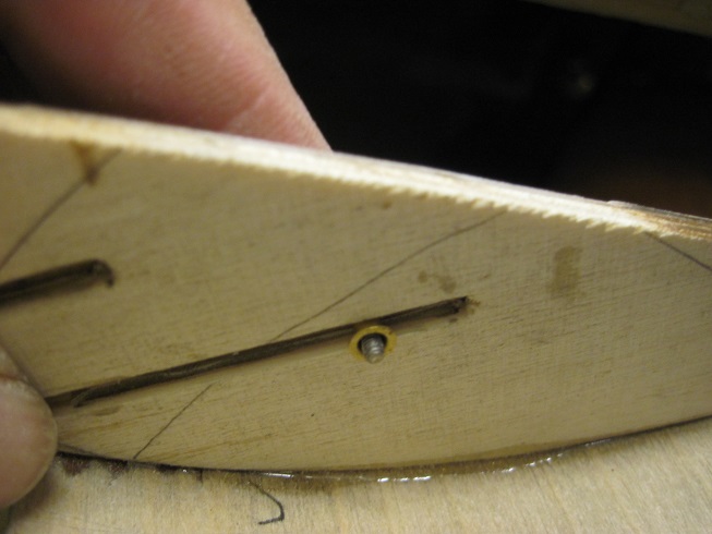
The frame that houses the door is complete, it has the slots to guide the door.
The track is a slot cut into the 1/8" ply that has the 1/32 birch ply laminated to it.
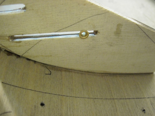
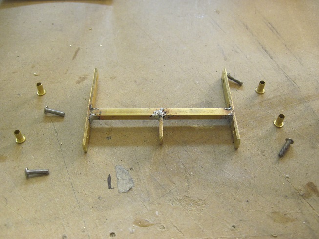
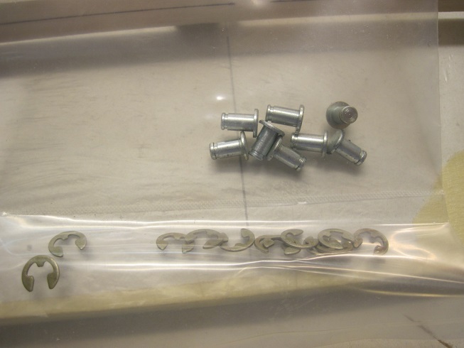
The hardware is brass soldered to make a linkage frame, plus this is threaded to receive the 2-56 button head shrews.
2-56 screws, and servo grommets.
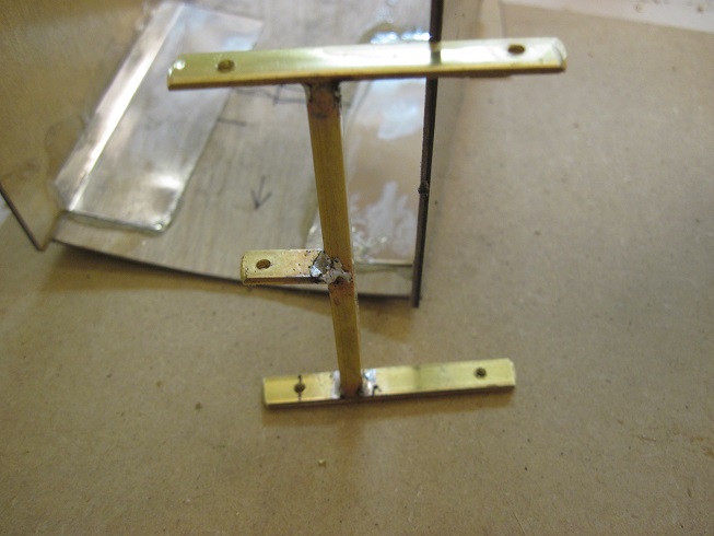
The doors have the carbon fiber laminated to the 1/32 ply.

To reinforce the joint I use tine as a L bracket, this works good.
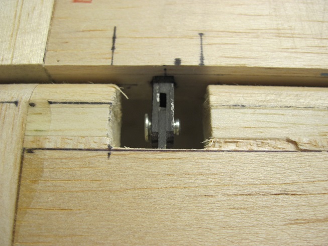
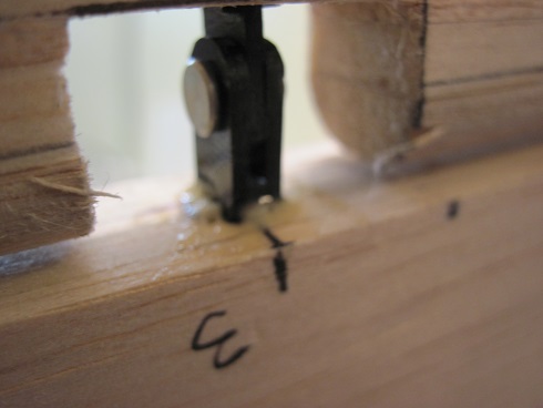
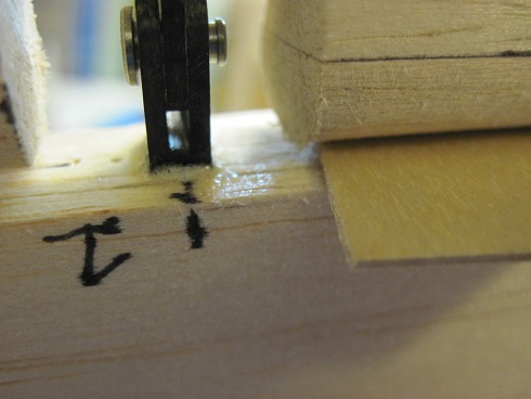
I did two slots instead of just one. The first one is strait and guides the door level backwards. The second is lower and guides the door level until it starts to open and then it dips down.
I like this so I can make the servo linkage on the upper one that is strait so it is pulling or pushing strait, no binding this way.
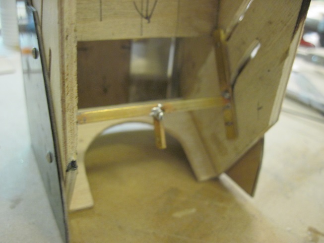
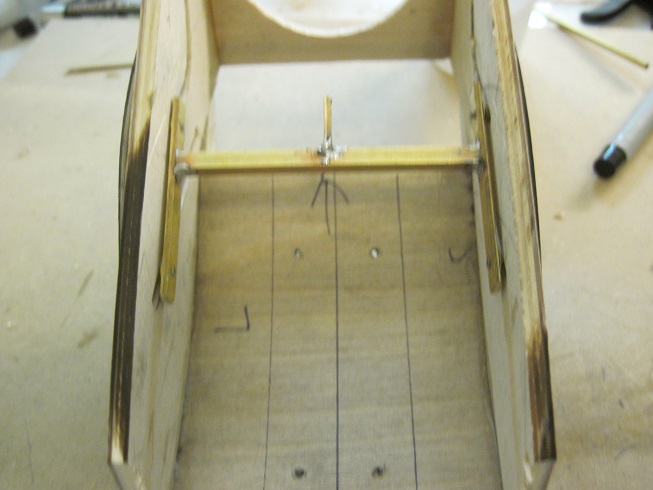
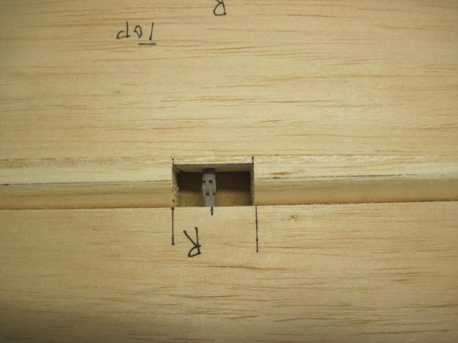
So all together and ready to drop in for final fitting.
I had to redo the mounting bracket to get the proper fit. I made it more compact.
This is glued in.
With the mount glued in I just drop the door assembly in and temp bolt it down.
I had the bracket for the linkage on backwards in the previous pics it was on the lower track, now it is on the upper strait track.
Pushrod lines up well. Not sure if I will use a servo or the liner actuator. The actuator will be smoother and I will have more control so we will see.
Here is a short vid of the working door.
https://youtu.be/TQg5nYNpNwg Next I will do the right side.
TB
So the left door is done and being fitted for adjustments.
The frame that houses the door is complete, it has the slots to guide the door.
The track is a slot cut into the 1/8" ply that has the 1/32 birch ply laminated to it.
The hardware is brass soldered to make a linkage frame, plus this is threaded to receive the 2-56 button head shrews.
2-56 screws, and servo grommets.
The doors have the carbon fiber laminated to the 1/32 ply.
To reinforce the joint I use tine as a L bracket, this works good.
I did two slots instead of just one. The first one is strait and guides the door level backwards. The second is lower and guides the door level until it starts to open and then it dips down.
I like this so I can make the servo linkage on the upper one that is strait so it is pulling or pushing strait, no binding this way.
So all together and ready to drop in for final fitting.
I had to redo the mounting bracket to get the proper fit. I made it more compact.
This is glued in.
With the mount glued in I just drop the door assembly in and temp bolt it down.
I had the bracket for the linkage on backwards in the previous pics it was on the lower track, now it is on the upper strait track.
Pushrod lines up well. Not sure if I will use a servo or the liner actuator. The actuator will be smoother and I will have more control so we will see.
Here is a short vid of the working door.
https://youtu.be/TQg5nYNpNwg Next I will do the right side.
TB
10-25-2015, 01:55 PM
#89
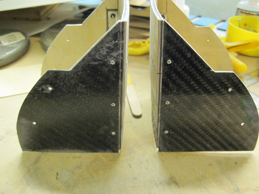
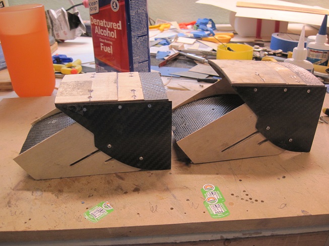
I got the second door all built and fine tuned the existing one so now they are ready to install.
I bolted the side panels as everything gets bolted on this bird.
8- #80 counter sunk SS screws on the door, and 3- #80 counter sunk SS on the side panels each side.
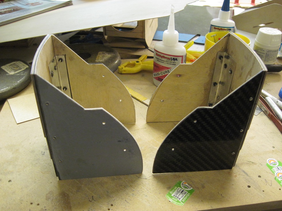
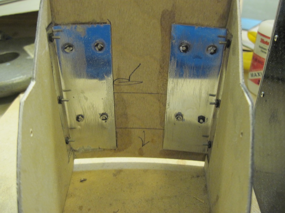
Sleds are matched up and done, had to do some fine tuning.
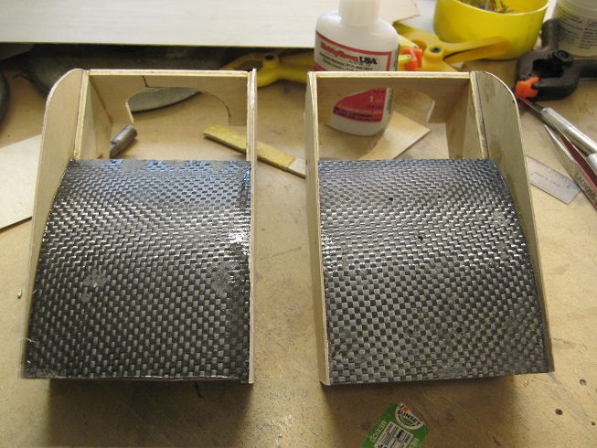
They drop in pretty good now and once they are all painted some lubrication for smooth in serves operation.
So there you have it, two inner cooler door sets.

TB
I bolted the side panels as everything gets bolted on this bird.
8- #80 counter sunk SS screws on the door, and 3- #80 counter sunk SS on the side panels each side.
Sleds are matched up and done, had to do some fine tuning.
They drop in pretty good now and once they are all painted some lubrication for smooth in serves operation.
So there you have it, two inner cooler door sets.
TB
11-01-2015, 03:00 PM
#91
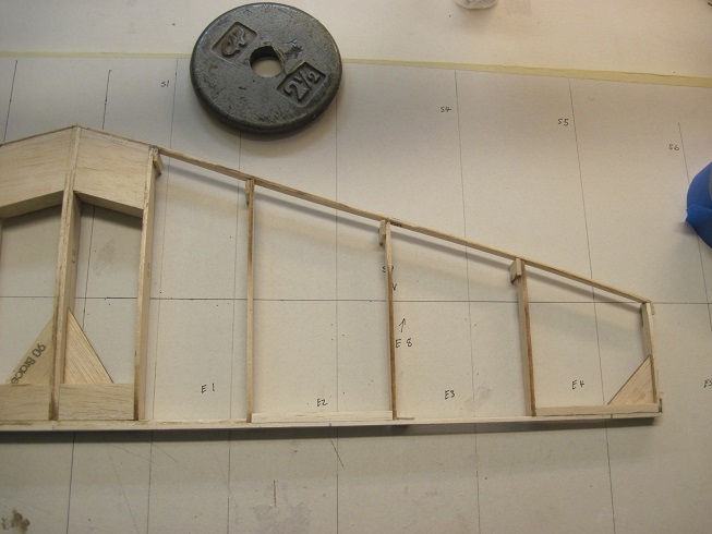
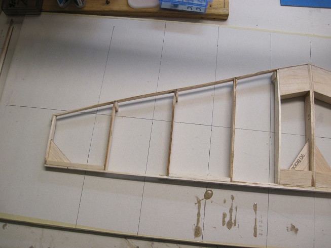
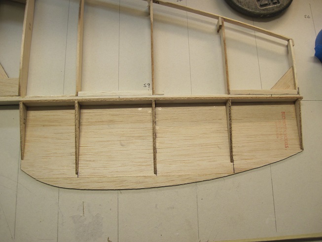
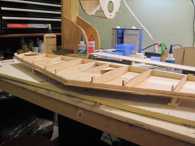
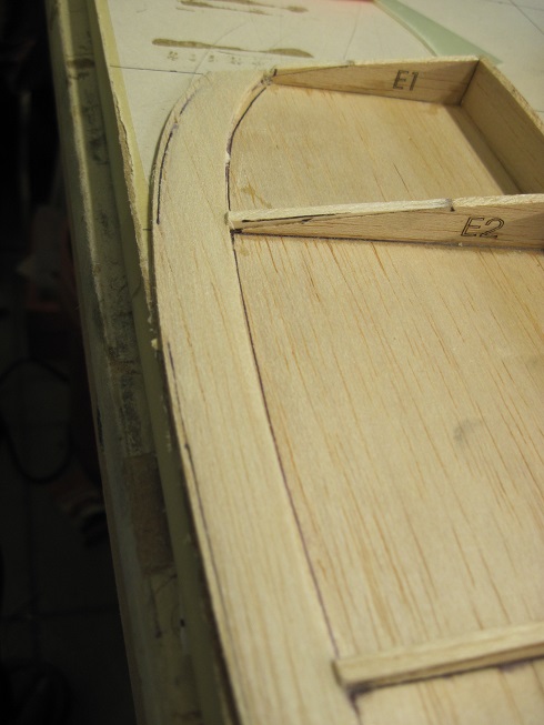
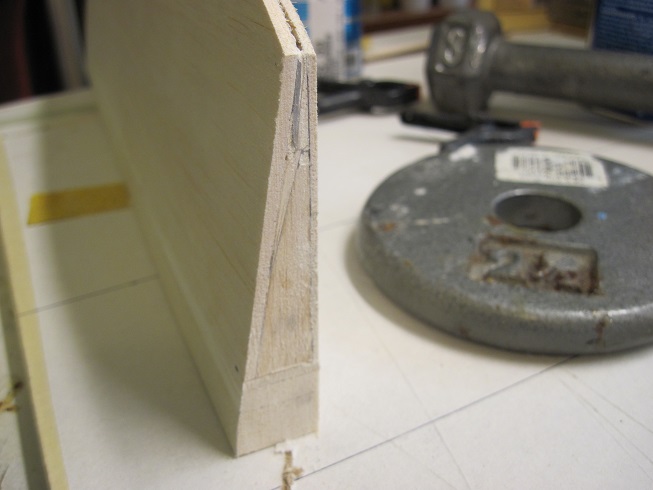
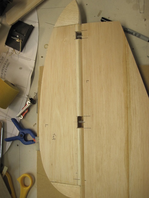
I started to work on the stab today.
At first I was like what the hell am I going to do with this as I do not like the method of how the stab is assembled. The parts are difficult to discern haw they go. In all the other P-47s I have built the stab is equal top and bottom, no difference. All my drawings show the same but the parts are not the same at the point they are attached to the TE.
So I just went for it and will adjust once I have something to work with.
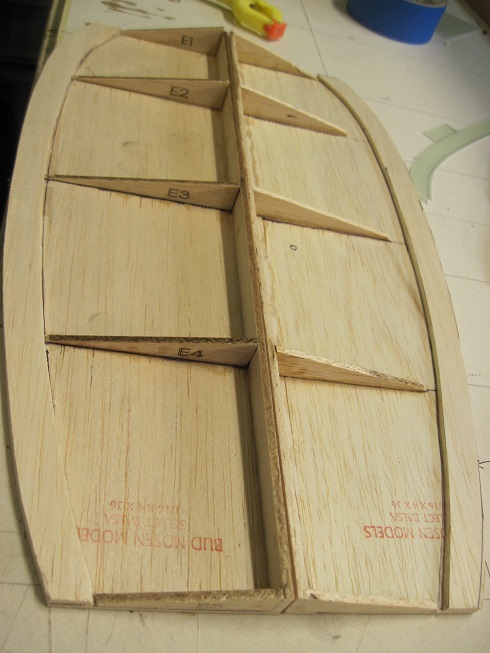
I glued the ribs in as best as I could figure out and will adjust later. They are uneven as once you get them in and they are plumb, the LE is all wavy.
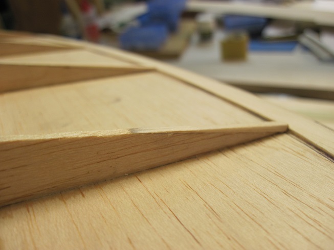
Once I sheet the sab I will sand the LE strait that should do it.
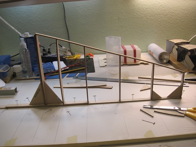
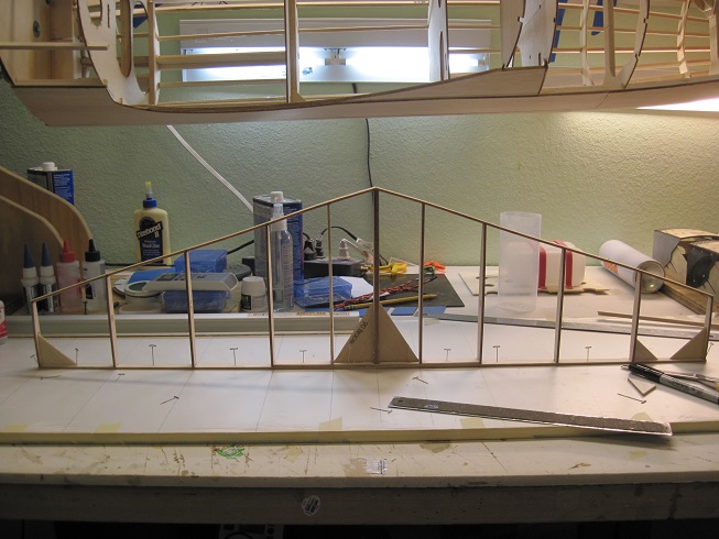
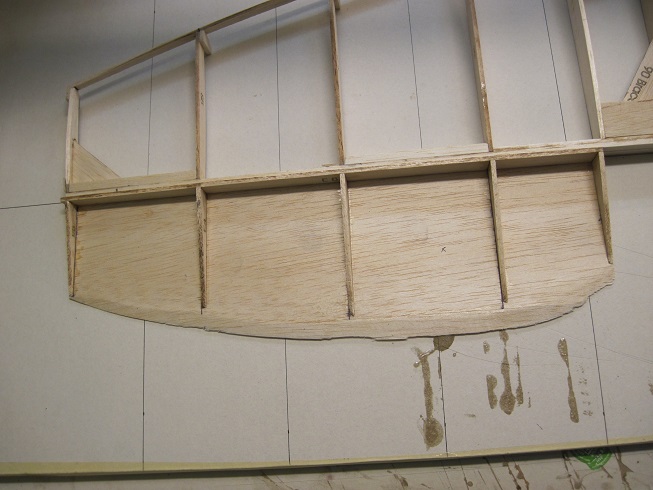
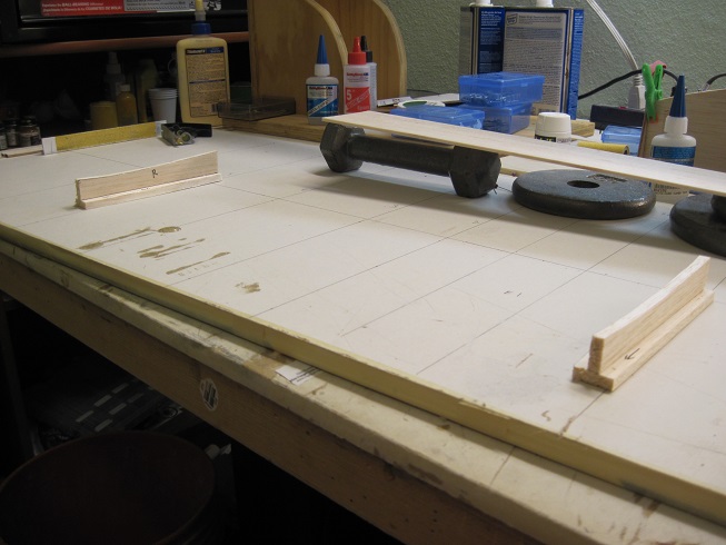
I much prefer the tab method of framing as I can lay the stab flat and true it up.
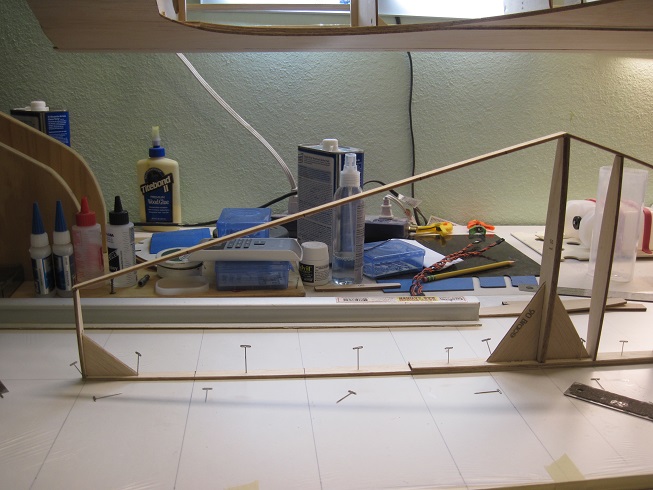
So a strait aluminum angle is used to get the TE strait and plumb.
A center line is drawn to keep it strait in elevation.
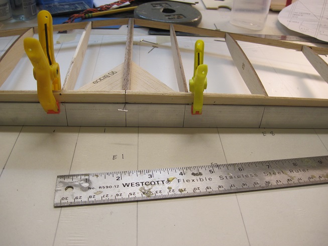
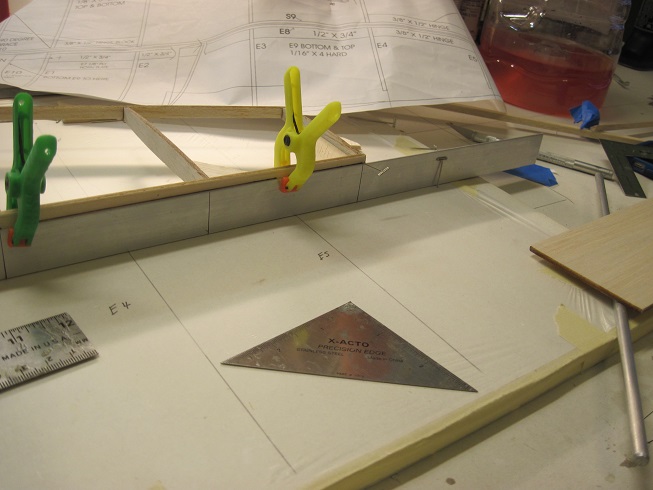
Then I glued tabs to the ribs to equal it out and keep it flat and level.
Control lines are on the board to keep it all square and aligned.
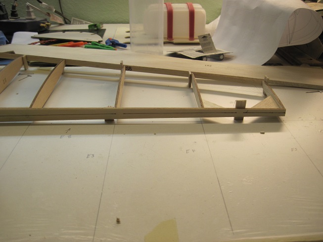
Some blocks to keep it firm for sanding and when I sheet the top.
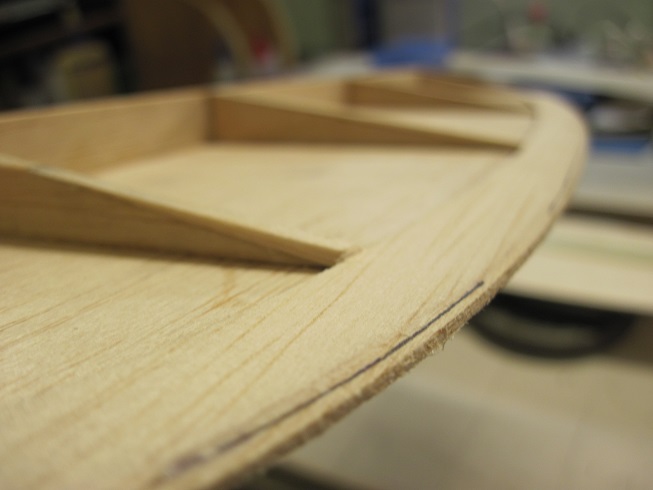
Now I can sand it and get it ready for hinges and sheeting.
I want to sheet the top to hold it all in place.


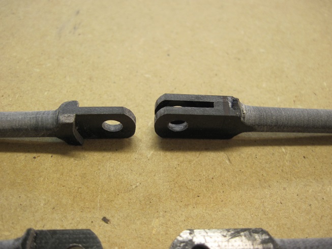
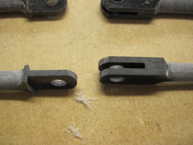
I am starting to layout the control torque rod and the hinges next.
The torque rod is solid 1/4" aluminum and will get cut into two halves.
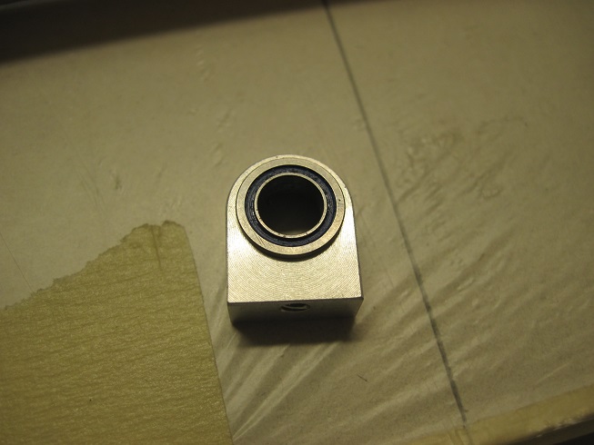
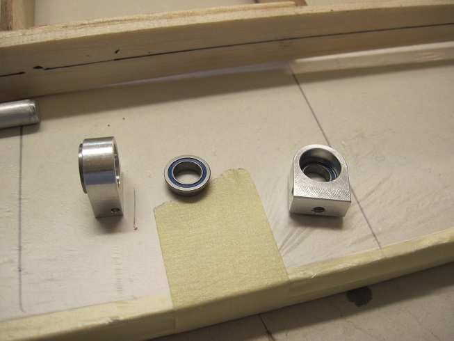
The inner hinge is what takes all the stress from the control arm so this has two sealed baring's per mount. T
he arm will be next to this on the inside. They are 1/4" x 1" aluminum arms from Dream works.
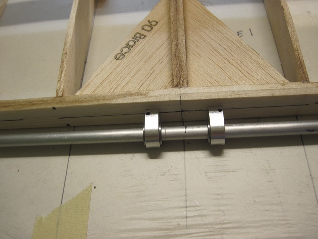
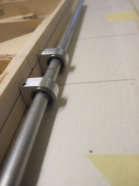
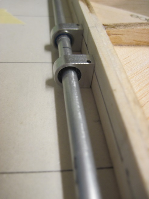
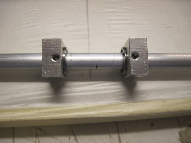
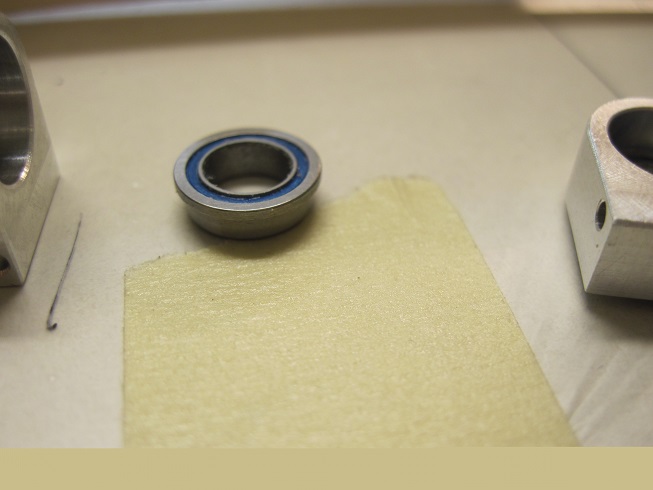
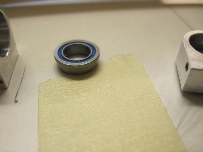
The inside bearing is held with a set screw and the outer will get a sleeve to hold it in.
They are 3/8" OD and 1/4" ID, they fit tight.
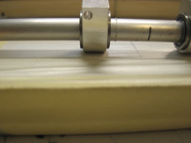
I will do the same at the lower hinge for the rudder as there will be a lot of tension from the pull-pull.
I will tap in two post to the bottom for mounting this to the stab.
These are the pins for the hinges I will be making out of G-10. that will be next.
TB
At first I was like what the hell am I going to do with this as I do not like the method of how the stab is assembled. The parts are difficult to discern haw they go. In all the other P-47s I have built the stab is equal top and bottom, no difference. All my drawings show the same but the parts are not the same at the point they are attached to the TE.
So I just went for it and will adjust once I have something to work with.
I glued the ribs in as best as I could figure out and will adjust later. They are uneven as once you get them in and they are plumb, the LE is all wavy.
Once I sheet the sab I will sand the LE strait that should do it.
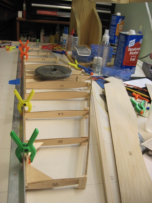
I much prefer the tab method of framing as I can lay the stab flat and true it up.
So a strait aluminum angle is used to get the TE strait and plumb.
A center line is drawn to keep it strait in elevation.
Then I glued tabs to the ribs to equal it out and keep it flat and level.
Control lines are on the board to keep it all square and aligned.
Some blocks to keep it firm for sanding and when I sheet the top.
Now I can sand it and get it ready for hinges and sheeting.
I want to sheet the top to hold it all in place.
I am starting to layout the control torque rod and the hinges next.
The torque rod is solid 1/4" aluminum and will get cut into two halves.
The inner hinge is what takes all the stress from the control arm so this has two sealed baring's per mount. T
he arm will be next to this on the inside. They are 1/4" x 1" aluminum arms from Dream works.
The inside bearing is held with a set screw and the outer will get a sleeve to hold it in.
They are 3/8" OD and 1/4" ID, they fit tight.
I will do the same at the lower hinge for the rudder as there will be a lot of tension from the pull-pull.
I will tap in two post to the bottom for mounting this to the stab.
These are the pins for the hinges I will be making out of G-10. that will be next.
TB
Last edited by TonyBuilder; 11-01-2015 at 03:02 PM.
11-05-2015, 12:47 PM
#92
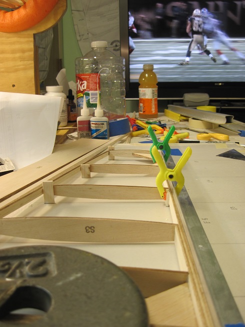
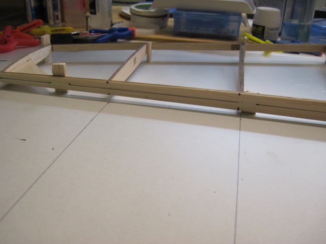
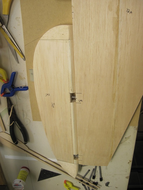
I added some blocking for the hinges.
The blocks are just to add strength to the TE, internal blocks will be added before the top skin is glued on.
Blocks are added for the center baring hinges for the torque rod.
Tip blocks for the two dowels that will pin the front.
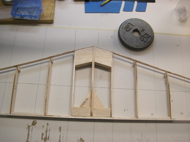
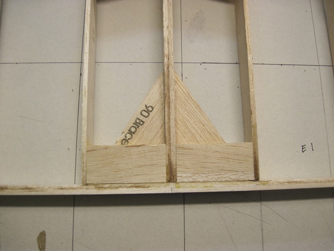
All sanded and ready for the skins.

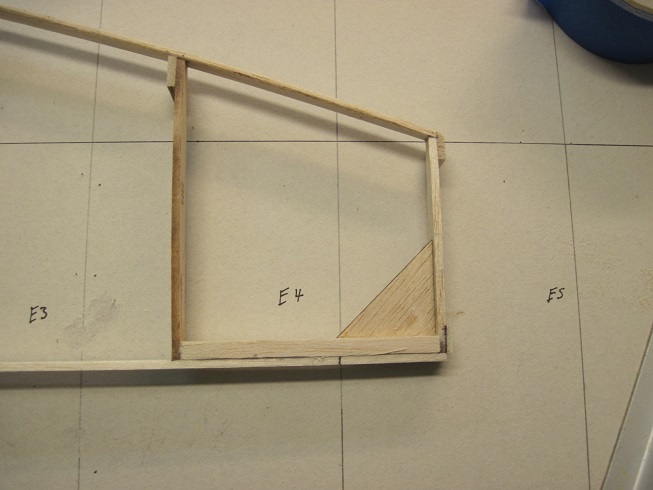
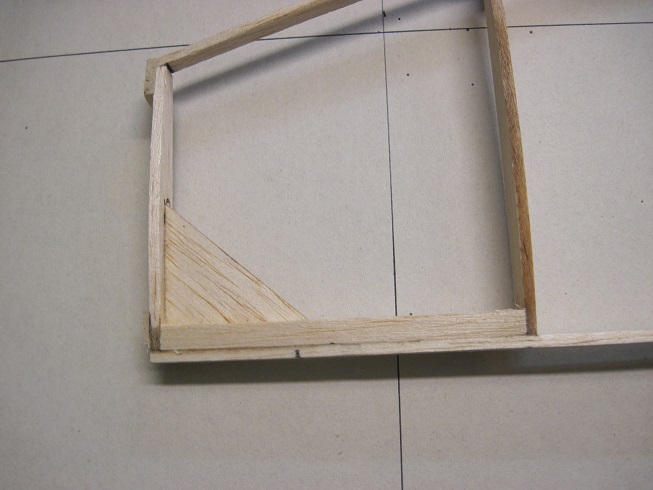
I framed up the elevators to see how those will work.
They need a bit of work to get them right.
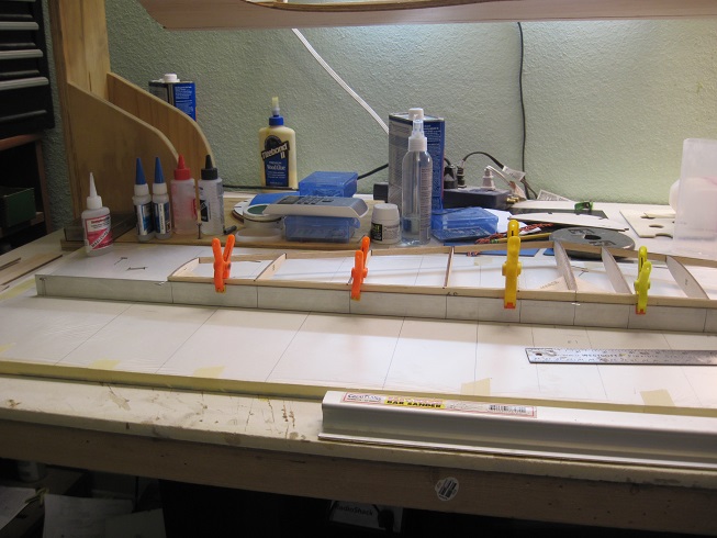
I am sheeting the bottom first to hold it all together.
Then I will install the hinges (dry) before I skin the top.
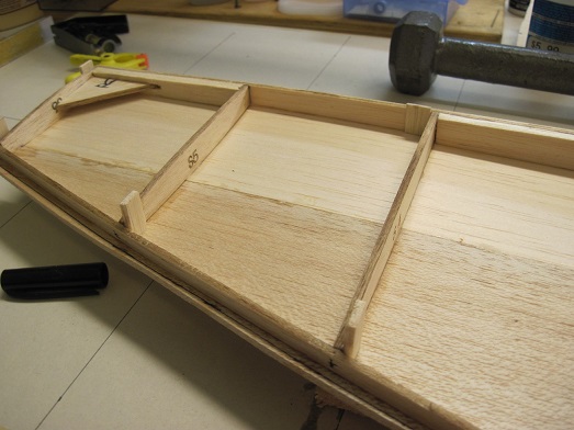
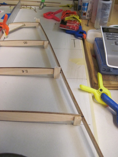
The tabs worked great to keep it all level and in the right place.
I made some contoured jigs for when I flip the stab and sheet the top, plus this is good for when I work on the hinges.
TB
The blocks are just to add strength to the TE, internal blocks will be added before the top skin is glued on.
Blocks are added for the center baring hinges for the torque rod.
Tip blocks for the two dowels that will pin the front.
All sanded and ready for the skins.
I framed up the elevators to see how those will work.
They need a bit of work to get them right.
I am sheeting the bottom first to hold it all together.
Then I will install the hinges (dry) before I skin the top.
The tabs worked great to keep it all level and in the right place.
I made some contoured jigs for when I flip the stab and sheet the top, plus this is good for when I work on the hinges.
TB
 11-07-2015, 03:26 PM
#94
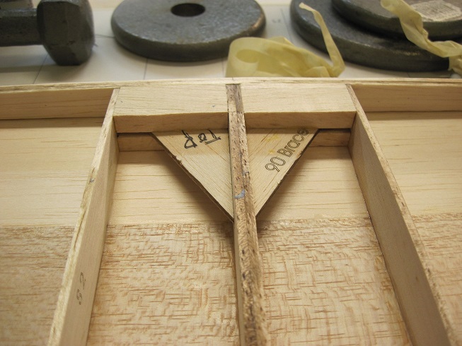
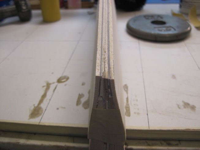
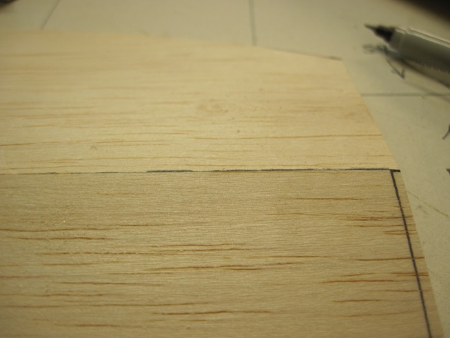
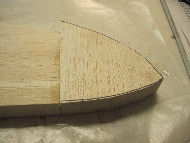
Been working on the elevators.
I added some balsa to the TE to build it up as I will be trying something new.
I never liked the thick fat TE on the surfaces, dead giveaway that it tis a model.
So I am using some thin G-10 that will get glued into the TE between the top and bottom skins.
Also the ribs are all of and different sizes so I need to add some balsa and get them all the same.
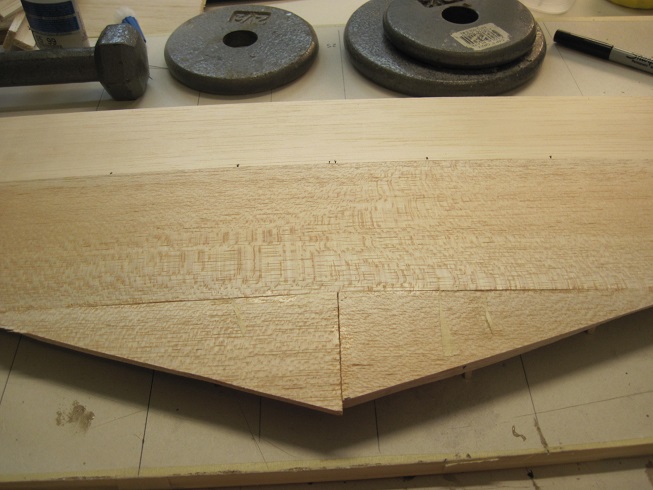
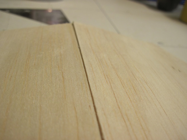
Once the TE fir was added I put the two halves together and sanded them so they would both be the same shape.
Next I sanded the added fir so it tapered to the bottom skin (1/16"). The fir was 1/8"
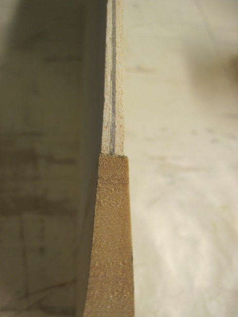
Once the fir was shaped I had to reses it to accommodate the G-10
I cut the G-10 and cut the trim tab into it
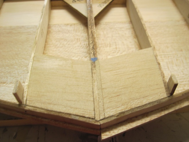
The G-10 glued in and the ribs all lined up as I fired them too.
The blocks are for the hinges and the one at the inner part is for a dowel to pin the torque rod to.
I held them back about 5/8" as I will be cutting 3/4 off for the new LE.
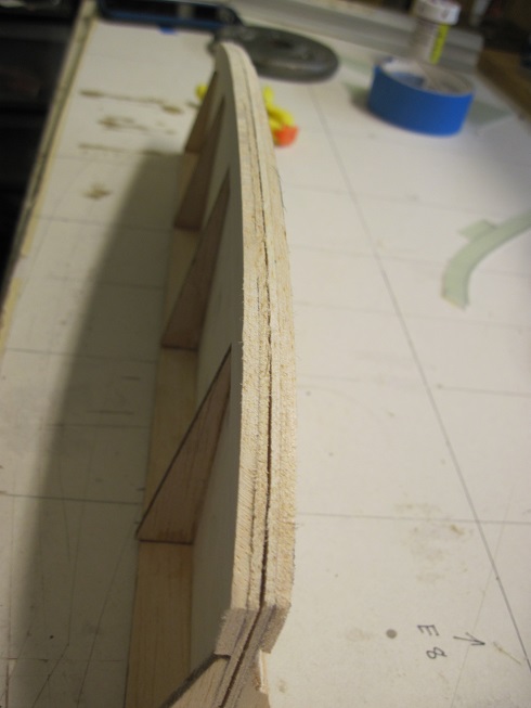
Top skin is now glued on and I joined the two halves together with tape so I could sand them equal.
You can see how the ribs are off in size and I should have checked them before I skinned them, but I used 3/32" balsa on the top so I could sand it to fit the stab.
I wont sand the TE until the ends are put on.
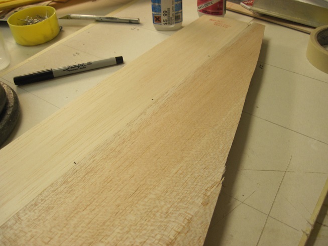
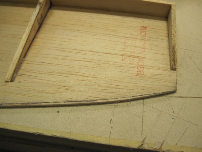
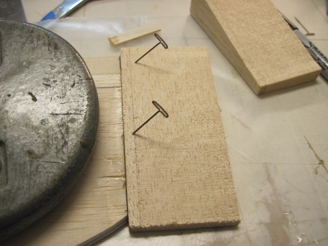
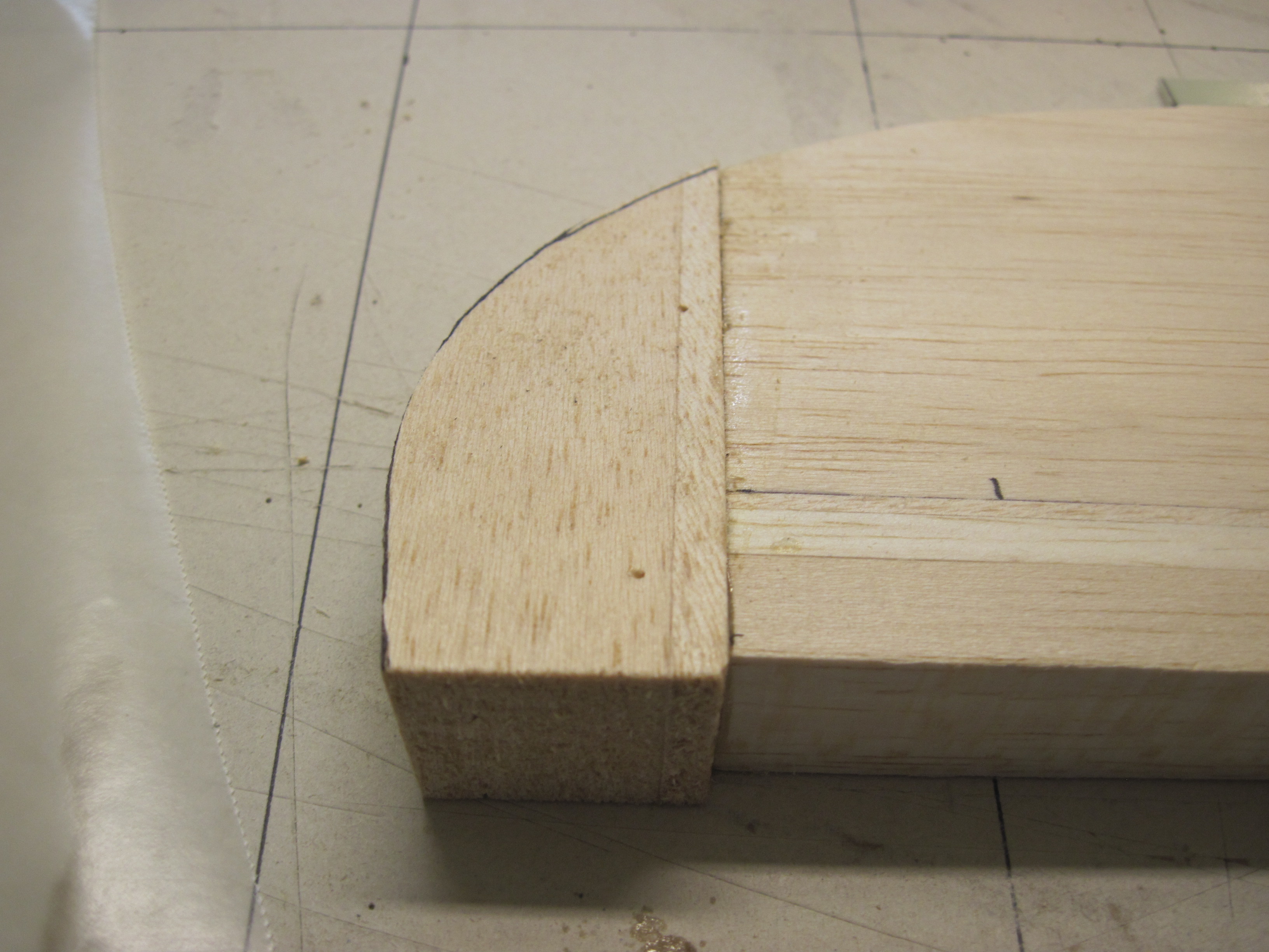
I cut the old LD off and sanded them equal.
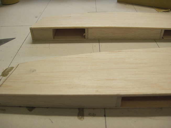
I first glue in a 3/32" balsa to face the elevator. Then a 1/4" balsa followed by a 1/2" balsa to bring the elevator up to size.
This will give me some sanding room on the TE.
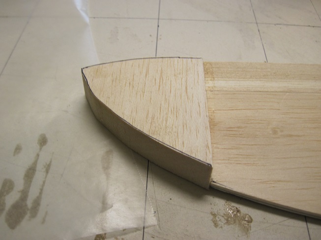
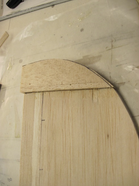
With the ends squared up and sanded I can add the ends.
Ends and tips all glued in. I wont sand them until the stab is ready to sand.
TB
I added some balsa to the TE to build it up as I will be trying something new.
I never liked the thick fat TE on the surfaces, dead giveaway that it tis a model.
So I am using some thin G-10 that will get glued into the TE between the top and bottom skins.
Also the ribs are all of and different sizes so I need to add some balsa and get them all the same.
Once the TE fir was added I put the two halves together and sanded them so they would both be the same shape.
Next I sanded the added fir so it tapered to the bottom skin (1/16"). The fir was 1/8"
Once the fir was shaped I had to reses it to accommodate the G-10
I cut the G-10 and cut the trim tab into it
The G-10 glued in and the ribs all lined up as I fired them too.
The blocks are for the hinges and the one at the inner part is for a dowel to pin the torque rod to.
I held them back about 5/8" as I will be cutting 3/4 off for the new LE.
Top skin is now glued on and I joined the two halves together with tape so I could sand them equal.
You can see how the ribs are off in size and I should have checked them before I skinned them, but I used 3/32" balsa on the top so I could sand it to fit the stab.
I wont sand the TE until the ends are put on.
I cut the old LD off and sanded them equal.
I first glue in a 3/32" balsa to face the elevator. Then a 1/4" balsa followed by a 1/2" balsa to bring the elevator up to size.
This will give me some sanding room on the TE.
With the ends squared up and sanded I can add the ends.
Ends and tips all glued in. I wont sand them until the stab is ready to sand.
TB
Last edited by TonyBuilder; 11-07-2015 at 03:51 PM.
11-14-2015, 03:55 AM
#96
Progress.
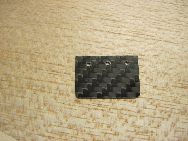
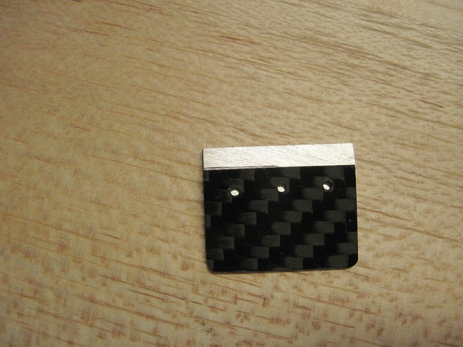
I have the hinges all fabricated and ready to install.
Hinges ate made from 1/32 black G-10 laminated three layers.
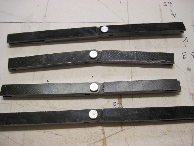
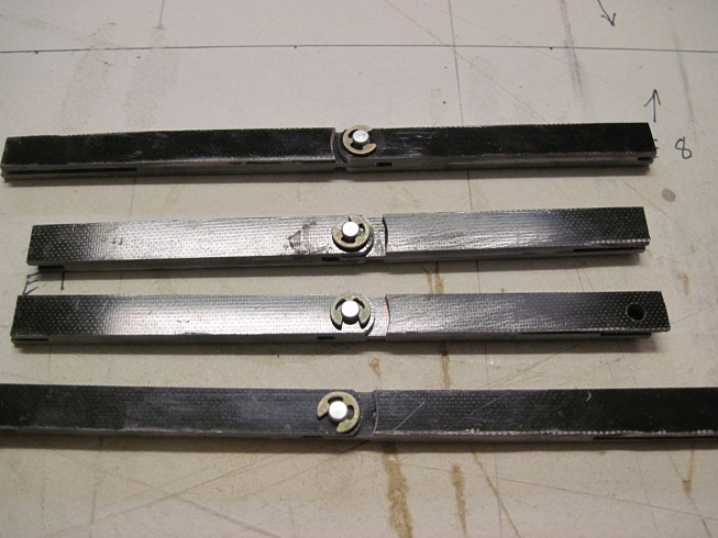
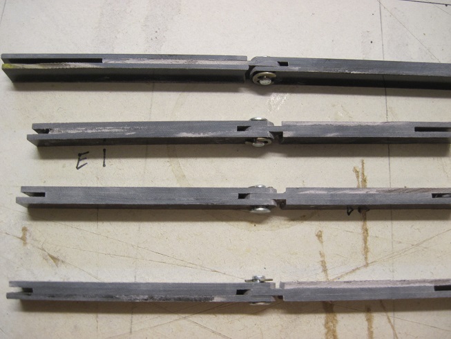
The pins are from Robart.

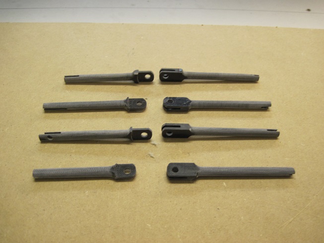
Robart hinge pins are used for initial fitting.
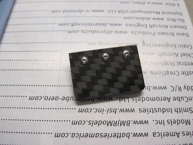
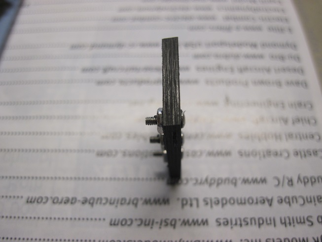
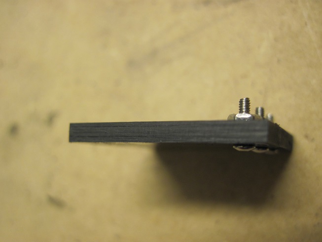
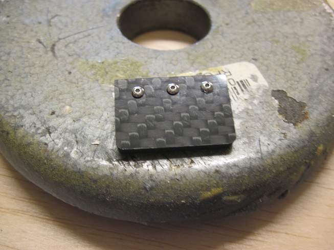
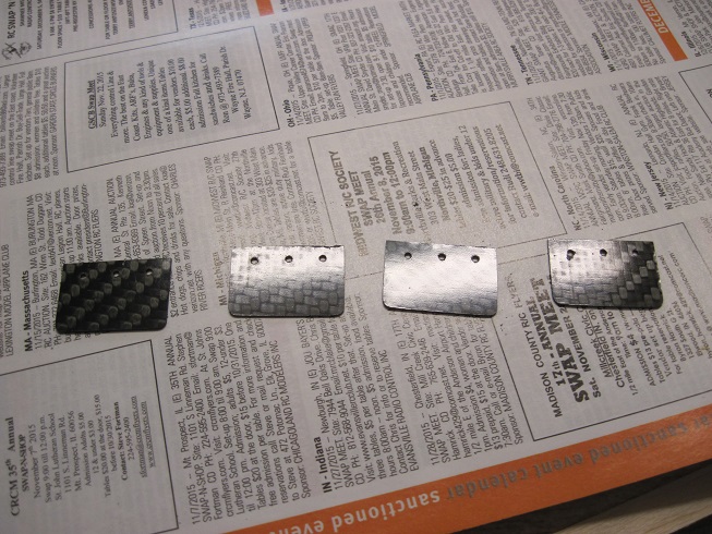
Tab covers are .19mm carbon fiber laminates. I drilled and bolted all for together and then sanded to size, this way they are all the same size.
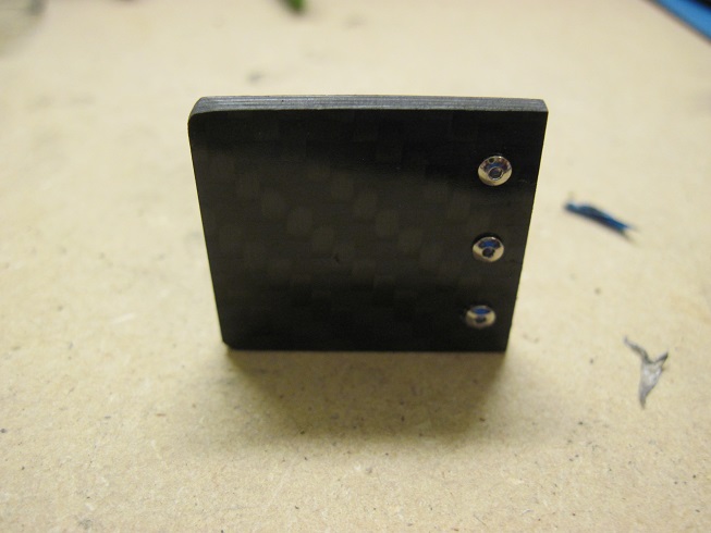
They will be bolted on with three #80 button head screws.
An aluminum plate will be recessed into the TE, tap threaded for the tabs.
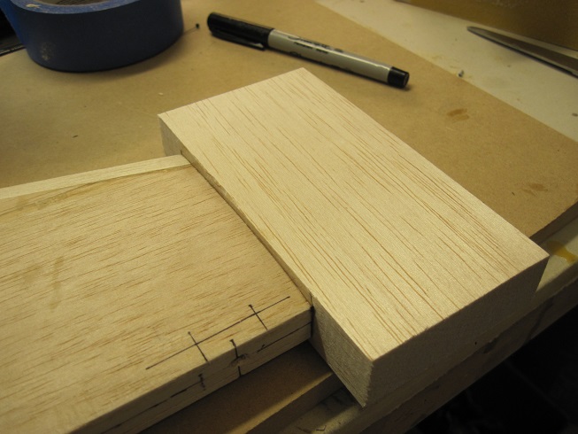
Tips are glued and rough sanded.
TB
I have the hinges all fabricated and ready to install.
Hinges ate made from 1/32 black G-10 laminated three layers.
The pins are from Robart.
Robart hinge pins are used for initial fitting.
Tab covers are .19mm carbon fiber laminates. I drilled and bolted all for together and then sanded to size, this way they are all the same size.
They will be bolted on with three #80 button head screws.
An aluminum plate will be recessed into the TE, tap threaded for the tabs.
Tips are glued and rough sanded.
TB
Last edited by TonyBuilder; 11-14-2015 at 04:20 AM.
11-15-2015, 05:59 AM
#99
Progress.
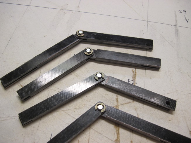
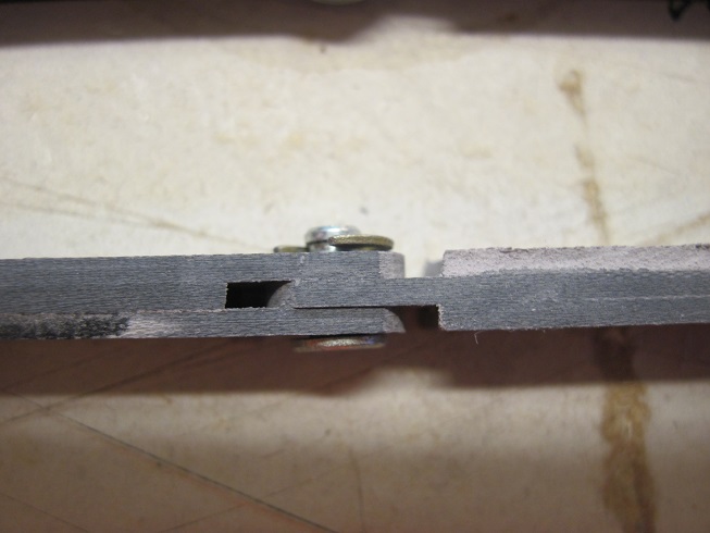
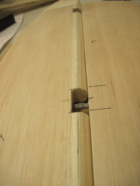
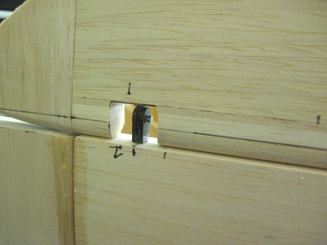
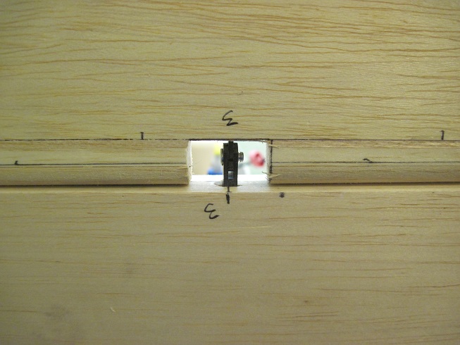
I am fitting the hinges for installation.
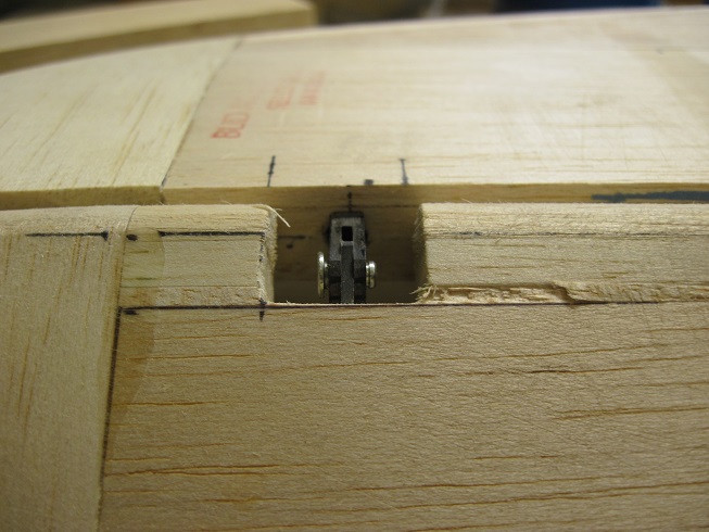
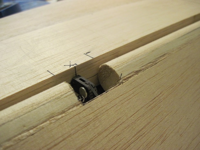
Installation of the pin as it was designed, I use tweezers and it works fine.
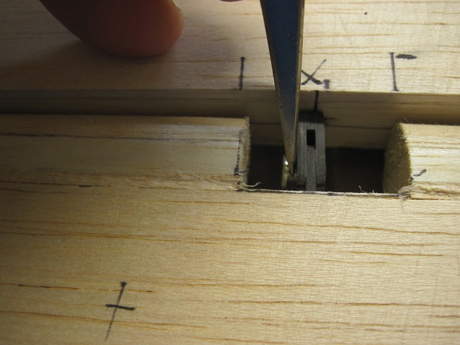
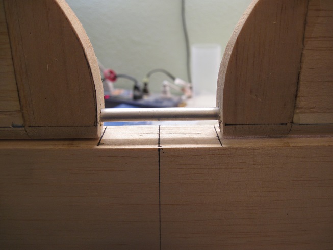
The aluminum torque rod is test fitted. Once everything is all lined up and working well I will glue the hinges, and torque rod in all together.
Then when its all dried I will cut the rod in the center separating the halves.
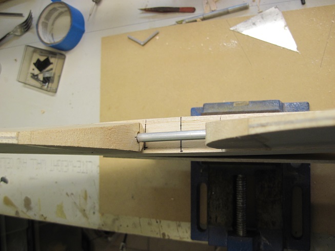
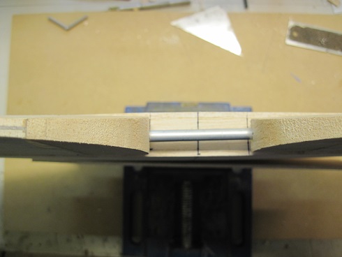
All looks good so far, the tabs will be fitted next.
TB
I am fitting the hinges for installation.
Installation of the pin as it was designed, I use tweezers and it works fine.
The aluminum torque rod is test fitted. Once everything is all lined up and working well I will glue the hinges, and torque rod in all together.
Then when its all dried I will cut the rod in the center separating the halves.
All looks good so far, the tabs will be fitted next.
TB
11-15-2015, 07:45 AM
#100
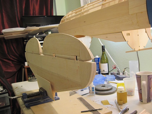
Progress.
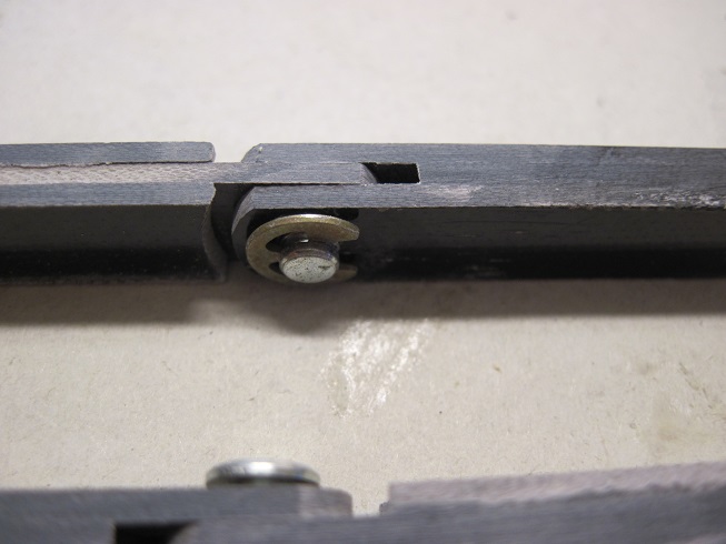
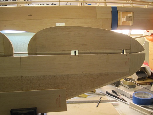
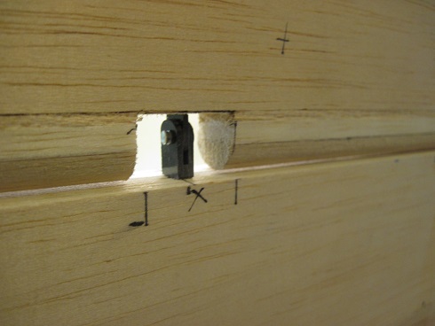
The third hinge with the bearings and the two control arms are test fitted to the elevator.
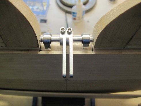
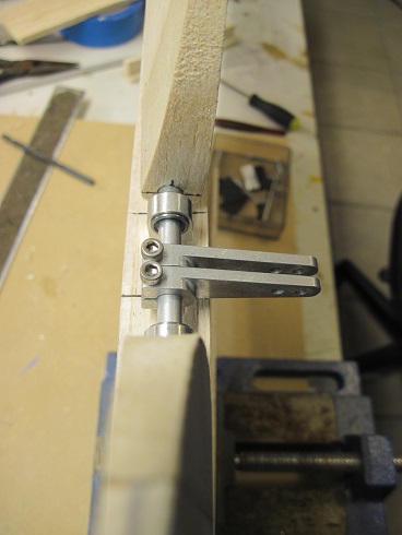
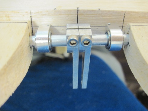
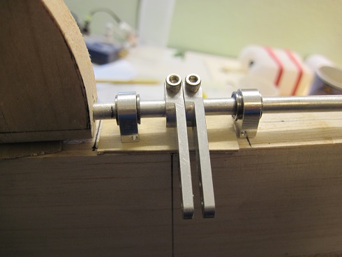
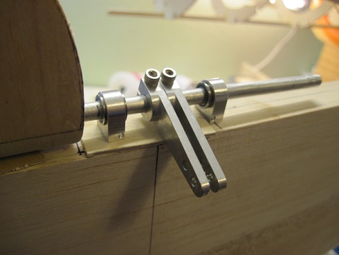
I have adjusted the hinges and I am gluing them in with gorilla glue as I like the expansion action it offers.
Once this sets up I will do the other side, then the elevator's, then the torque rod.
TB
The third hinge with the bearings and the two control arms are test fitted to the elevator.
I have adjusted the hinges and I am gluing them in with gorilla glue as I like the expansion action it offers.
Once this sets up I will do the other side, then the elevator's, then the torque rod.
TB