


Balsa USA Smoothie XL Build
 11-28-2017, 06:34 PM
#101
GREAT Thread. I've read the complete story of your awesome build. A question comes to me as far as the CG. I'm planning this build with a DA-35 up front, with a Pitts style muffler. You mentioned possibly being nose heavy. Do you think it warrants putting two elevator servos in the tail? I prefer this setup in my large planes. That coupled with a pull-pull system for the rudder. Thanks....
 11-30-2017, 01:23 PM
#102

Thread Starter
Join Date: Oct 2006
Location: Collierville, TN
Posts: 602
Likes: 0
Received 0 Likes
on
0 Posts
GREAT Thread. I've read the complete story of your awesome build. A question comes to me as far as the CG. I'm planning this build with a DA-35 up front, with a Pitts style muffler. You mentioned possibly being nose heavy. Do you think it warrants putting two elevator servos in the tail? I prefer this setup in my large planes. That coupled with a pull-pull system for the rudder. Thanks....
Last edited by pappy35; 11-30-2017 at 01:36 PM.
11-30-2017, 09:22 PM
#103
You’re welcome pappy. I can only hope to end up in that weight range. I do agree on not liking long push rods on this size model especially. From your experience with having to add that much weight in the tail a couple of 1.5 - 2 oz servos back there wouldn’t seem to hurt a thing. I appreciate your answering my question. I intend to reread this (as well as check6’s) thread before I start my build. I’ll have to clear out a few cobwebs to remember how to figure out the firewall angles as you did on yours, lol. Cheers, cd.
12-26-2017, 10:21 AM
#106
I have a question
I am just starting my build and am still at the making sure I know what I am about stage (grouping parts, removing them from sheets, etc) I am looking at this build and the Landing Gear keeps popping up in my mind.. One of the reasons I like to build myself AND especially Giant Scale is that I like winding up with a trouble free aircraft... There is just something about real hinges heavy control horns, big hefty push rods, etc which screams quality and durability.
so....
though the Landing gear looks pretty nice I can visualize the wood covering and the wheel pants constantly falling off the wires and constantly having to mess with it...
Is this a real concern? I am thinking about having TNT build me a set of aluminum ones..
good? bad?
love the look that they have now but.
12-27-2017, 07:45 AM
#107

My Feedback: (6)
Join Date: Nov 2004
Location: Clemmons, NC
Posts: 21
Likes: 0
Received 0 Likes
on
0 Posts
Hi Coleboom -
I've seen issues with the wood gear coverings on some of my friends WWI airplanes that use the same technique for attachment. I decided to do the following on mine:
1) Rough the gear legs up a bit
2) Use hysol 9462 to attach the wood to the gear
3) Fiberglass all the way around with .75 oz glass. Helps a little with integrity, but not much. Prevents slight taps from breaking them off. Mostly for finishing.
4) At the bottom, hysol 9462 a piece of 0.15 thick G10 material on both sides, to span both pieces of wood. This should lock the wood pieces together, plus make a nice surface for finishing
I purchased fiberglass wheel pants from Fiberglass Specialities; I like them better than the ABS. I also purchased a cowl from them. The wheel pants seem to attach pretty solidly; as long as I don't completely butcher the landings, they should be fine.
Attached are some pictures of the gear ready for paint. Hope this helps.
Regards,
Greg
The following users liked this post:
[email protected] (02-24-2021)
01-22-2018, 01:28 PM
#109
In hopes of not having to add weight to the tail, for proper cg. I�ve installed two elevator servos in the tail, below the stabilizer. I plan to install a DA35 up front and pull-pull rudder servo at the rear of the radio compartment.
01-22-2018, 01:38 PM
#110
Thread Starter
Join Date: Oct 2006
Location: Collierville, TN
Posts: 602
Likes: 0
Received 0 Likes
on
0 Posts
That's gonna work out really well for you. As I've mentioned, my Monokoted Smoothie XL needed about 6oz of lead in the tail to balance with a DL35RA up front. Quite a few mounting screws there. Not sure you needed 6 but in this case I think more weight back there is better. 8-)
01-22-2018, 01:48 PM
#111
FINALLY got the cowl mounted! Using a term my wife introduced me to, I "borrowed a lot of trouble" by incorporating right/down thrust into a kit that didn't have this designed in. First there was the issue of aligning and securing the firewall at the correct angle. Then finding the location (offset) for the mount holes ensure the spinner lines up. Finally, fiddling with the cowl ring (which is molded for 0-0 angle) to ensure a nice, tight, even gap all around. I'm fussy about some things and a tight spinner gap is a peeve (much to my own detriment) of mine.
Pic 1: Overall view of the installed cowling.
Pic 2, 3 and 4: The tapered cowl ring, spinner gap, sanding block with 120-grit paper. I will be applying filler (finishing resin and microballons as required) to seal the balsa. I probably should have used plywood but that would have been a lot harder to sand and we'll see how this comes out after I prime the cowling. I'll probably open the gap up just a bit more as it's a little too tight like it is but that'll work itself out when I get closer to prepping for finish application (either Solartex or Monokote).
Pic 5: This is one of the few places I've found an error in the instructions. The pictures in the manual came from a Facebook build (or at least I'm pretty sure they did) where the builder was using a large Saito 4-stroke and had to modify the cowling to accommodate the much taller engine. The instructions show how to add balsa extensions to carry this scoop aft to just forward of the front landing gear mount. I found that using the stock cowling and building the extension as shown would have closed off the exit area so I opted to leave it off altogether. As you can see there would have been a much smaller exit area and, to me, this is an unneeded feature that is just dying to get broken off at some point. The appearance of the area is fine just like it is so, well, that's it then. 8-)
01-23-2018, 09:48 AM
#112
Thread Starter
Join Date: Oct 2006
Location: Collierville, TN
Posts: 602
Likes: 0
Received 0 Likes
on
0 Posts
On the maiden it required no trim and has no tendency to pitch or yaw with throttle changes. On an upline for instance I can go from part-power to full-power with no rudder compensation. Now, having said that, never having flown one built with 0/0 offsets I can't really know if it's my offsets or the plane. It was a LOT of trouble to incorporate and, since this isn't an IMAC plane, I'm not sure if it really mattered. I was looking for a challenge and this seemed like a great way to present myself one.
On another note, I am considering cutting off the inlet part of the cowling. The engine has been really troublesome resulting in 8-9 dead stick landings, two of which ripped the wings off (the design is such that it was easily repairable BTY). I've tried setting and resetting the needles to no avail. I added a heat shield between the muffler and the carb. Zilch. So I've pretty much convinced myself that it's not getting enough cooling (it runs just fine for the first two or three minutes but dies after any time spent at idle - like during practice landing approaches). Heed my advice not to add that bit of wood after the cowling as I don't think there's enough cooling flow even without.
This brings up one good argument for not building in engine offsets: It requires modifying the cowling so replacing it with a new one then requires quite a bit of work to refit it. Food for thought...
01-23-2018, 10:39 AM
#113
On the maiden it required no trim and has no tendency to pitch or yaw with throttle changes. On an upline for instance I can go from part-power to full-power with no rudder compensation. Now, having said that, never having flown one built with 0/0 offsets I can't really know if it's my offsets or the plane. It was a LOT of trouble to incorporate and, since this isn't an IMAC plane, I'm not sure if it really mattered. I was looking for a challenge and this seemed like a great way to present myself one.
On another note, I am considering cutting off the inlet part of the cowling. The engine has been really troublesome resulting in 8-9 dead stick landings, two of which ripped the wings off (the design is such that it was easily repairable BTY). I've tried setting and resetting the needles to no avail. I added a heat shield between the muffler and the carb. Zilch. So I've pretty much convinced myself that it's not getting enough cooling (it runs just fine for the first two or three minutes but dies after any time spent at idle - like during practice landing approaches). Heed my advice not to add that bit of wood after the cowling as I don't think there's enough cooling flow even without.
This brings up one good argument for not building in engine offsets: It requires modifying the cowling so replacing it with a new one then requires quite a bit of work to refit it. Food for thought...
On another note, I am considering cutting off the inlet part of the cowling. The engine has been really troublesome resulting in 8-9 dead stick landings, two of which ripped the wings off (the design is such that it was easily repairable BTY). I've tried setting and resetting the needles to no avail. I added a heat shield between the muffler and the carb. Zilch. So I've pretty much convinced myself that it's not getting enough cooling (it runs just fine for the first two or three minutes but dies after any time spent at idle - like during practice landing approaches). Heed my advice not to add that bit of wood after the cowling as I don't think there's enough cooling flow even without.
This brings up one good argument for not building in engine offsets: It requires modifying the cowling so replacing it with a new one then requires quite a bit of work to refit it. Food for thought...
In the end I believe I'll build it 0/0 and take my chances. I don't profess to being a good enough pilot to maybe even note the difference. Possibly, if a person had two like models side-by-side that you could fly one after the other you'd know the true answer....
Just looking at the plans and parts/pieces, I agree there doesn't seem to be allot of airflow for the engine. I did put 3 (1/2 inch wide) slots in the plywood cover between the gear and am going to knock out the oval in the bulkhead (I believe it's F3). Once I have it put together, it'll give me a better idea as to how the air will flow through and/or if any more mods maybe needed. I try to force air across the cylinder head fins, using cardboard/foam stock you can get at WalMart, in crafts. It glues in good with super glues and seems to be durable. I try to copy what they do with life size planes as far as engine baffling. I haven't done any measuring as I'm not that far with the build yet as to the size of the entrance vs exit holes. I try to have close to 3 times more exit airspace than entrance. I didn't see a large need for the cowl exit extensions, and most likely won't add them, based on your advice.
Thanks again for your consideration, in answering my questions. Doug
p.s. You might try a QuikFire fuel filter. I've used them and like the theory/operation. QuikFire - Fuel Balancer and Filter - JL Power Products
Last edited by Crewdog; 01-23-2018 at 10:46 AM.
01-23-2018, 11:09 AM
#114
Thread Starter
Join Date: Oct 2006
Location: Collierville, TN
Posts: 602
Likes: 0
Received 0 Likes
on
0 Posts
The main problem with cooling flow is the location of the muffler. I added slots to that plate and knocked out F3 but the muffler does a really good job of blocking the airflow via that path. 3:1 inlet to outlet ratio is good. More is better but the cowl, as designed, is already pretty restricted and I don't think baffling will do anything but further restrict inlet flow. I like the look of that inlet under the spinner so what I'm thinking is shaving-off a large percentage the 'duct' starting just behind the front -side of the cylinder and see what that does.
I have a thermocouple mounted to the aft side of the cylinder between the top two fins and am seeing temps in high 200's with ambient temps in the high 80's. That's fairly high but, with the carb above the muffler in a dead zone (it's up out of any cooling flow), I think it's heat-soaking and going lean. I ran it without the cowling for it's first three flights and, though rich at first with the associated burbling, it ran fine. I put the cowling on and five minutes into flight on a practice approach when I went to climb-power it gasps and quits (lean). These problems I'm having only happen after a few minutes of flight. I haven't read of anyone else having cooling problems (yet) so it may really just be my engine (or my admittedly poor engine-tuning skills).
You will save yourself a bunch of trouble going with the 0-0 mount but with a Pitts-style muffler pay extra attention to cooling air. I'm still kicking myself for getting the DL rather than the DA.
Last edited by pappy35; 01-23-2018 at 11:11 AM.
01-23-2018, 02:38 PM
#115
This will be my first DA engine. It has a side exhaust exit so the muffler is a wrap around Pitts type. I glued in the firewall today at 0/0 and will move forward tomorrow, if life doesn’t get in the way.
I’m trying to think of a source of “fresh air” you could provide to the carb? Even if you were to drill a hole in the firewall the air behind it is heated. The way this plane is setup there really isn’t a way to get clean cool air to the carb.
I don’t know if inlet baffling would restrict the flow but rather direct the flow? It will be helpful for me, once I have the engine compartment fully assembled. The ole adage of, a picture is worth a thousand words, is trumpeting in my mind.
Dont know it it would fit but a passing thought for your consideration is a header - canister exhaust? If it would fit the installation, it may remove some of the heat?
01-23-2018, 03:09 PM
#116
pappy35: I too had a problem with cooling with a DLE20RA:
I built an air scoop on top of the cowl using one half of a blister pack from a small spinner. After cutting the appropriate size/shape hole in the top nose, trimmed the plastic leaving a small flange on the flat part to glue to the bottom of the cowl. A bit of fiberglass underneath the plastic and a small weight to squish the top to an oval shape resulted in an acceptable (to me) look for the scoop. Works great. YMMV. Beats cutting up the cowl.
Also, hate to spend many $$$ on pilots so make my own. Here's R2D2. Foam ball with misc electronic parts. Ignition LED and Tach behind his head.
01-23-2018, 07:57 PM
#118
Thread Starter
Join Date: Oct 2006
Location: Collierville, TN
Posts: 602
Likes: 0
Received 0 Likes
on
0 Posts
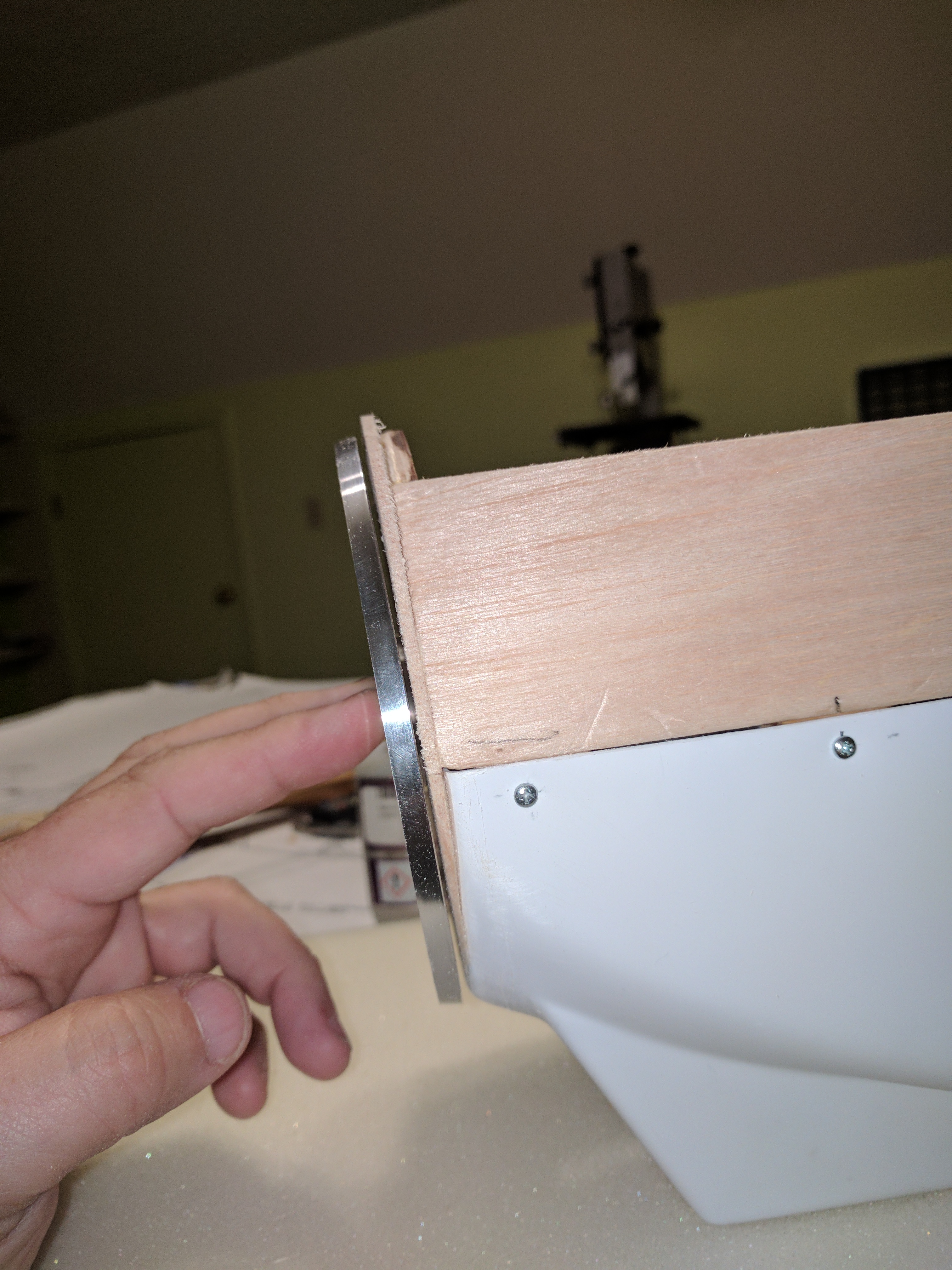
In this image you can see the hole for the carburetor air intake in the firewall. The air in the fuselage is not heated as the horizontal former (labeled "tank floor") separates the heated engine cooling air from the fuselage cavity. Engine cooling air flows through the cowl under the tank floor and out the hatch between the LG mounts. With wing and hatch in place I imagine the carb is ingesting some warmer air from the engine compartment but most would be coming in through the fuse (in through the rear pushrod exits and the seams at the wing saddle and hatch). The carb is really close to the firewall. Close enough that I think this is true. Who knows, my days of having access to CFD codes is long ago (haha) but it seems to me that heated air flowing into the carb wouldn't be a factor. I installed a static pressure air nipple to the carb diaphragm plate and ran that back into the fuse and that didn't seem to help either. I like that little air scoop. Pretty neat.
01-23-2018, 07:59 PM
#119
Thread Starter
Join Date: Oct 2006
Location: Collierville, TN
Posts: 602
Likes: 0
Received 0 Likes
on
0 Posts
I don't have an image of the heat shield I MacGyvered but it's a piece of thin (~10 mil) stainless that snaps over the lower two (upper in this image) engine standoffs. The intention was for it to reflect radiate heat from the muffler which sits right up close to the lower standoffs. That didn't help either but I liked how it turned out so I left in there. 8-)
01-24-2018, 07:34 PM
#120
I got my engine in place today so understand more about the airflow than before. A glaring issue (to me anyway)is the area above the engine. This would be where the first knockout is in the fuselage top from just behind the spinner. It seems to me this area would allow the cooling air to enter, raise, and tumble, thus disrupting a smooth airflow through the compartment? I’ve not made final decisions yet but I think I’m going to glue that knockout back in. As well I think I’m going to make a baffling to prevent air from entering and crossing above the base of the cylinder? To me the way that area is designed the air needs some directing to keep it flowing smoothly across the cylinder area and on its way to the exit?
Last edited by Crewdog; 01-24-2018 at 07:38 PM.
01-24-2018, 08:05 PM
#121
Thread Starter
Join Date: Oct 2006
Location: Collierville, TN
Posts: 602
Likes: 0
Received 0 Likes
on
0 Posts
When you say "first knockout" what do you mean? Can you take a picture or perhaps draw a diagram? There is only one path for air to enter the fuselage and that's through the cowl opening below the spinner. This flow is impeded from flowing around the entire cylinder, for a Pitts-style muffler, but the body of the muffler itself.
01-25-2018, 07:18 AM
#122
The hole I�m talking about is in the fuselage crutch. It seems to invite an area for the air to tumble into and oppose a smooth flow through the engine compartment and across the engine cylinder.
01-25-2018, 08:35 AM
#123
Thread Starter
Join Date: Oct 2006
Location: Collierville, TN
Posts: 602
Likes: 0
Received 0 Likes
on
0 Posts
Ah. I see. There will be some air movement through this area but the majority will enter and exit via the lower cowl. If you think about it, all the air in the fuselage doesn't really have anywhere to go other than push out through the wing saddle and hatch gap. Imagine a packed subway car with only two open doors at opposite ends. You are outside the car at one end and want to get to the other end. Do you push your way through the crowded car or just walk outside to get there?
So, with regards to flow this area is high(er) pressure and, hence, air will tend to flow along the path of least resistance (lowerer pressure).
So, with regards to flow this area is high(er) pressure and, hence, air will tend to flow along the path of least resistance (lowerer pressure).
01-25-2018, 04:55 PM
#124
I don't disagree, Pappy, a large portion (or all) of the effort is based on the venturi principle. I see some possible road blocks in the way???
I try to provide a directed airflow through to the engine. After the air hits the fins and doesn't go around it in a possible hap hazard manner, I allow it to escape as it wishes for the most part.
I covered the area from the F1 (nose ring) across the N2 and N3 formers with the paper foam material today. Then smoothed/directed the sides to a vertical wall I put in place on the aft side of the rear nose former, that contours the bottom portion of the motor. It makes a dam to force any air entering from behind the spinner to go down and toward the fin area of the engine. I haven't worked on, but plan to funnel the air coming in via the inlet opening of the lower cowl across the cylinder fins, using the same material. I did make a ramp from the bottom of the tank floor up to the opening of the F3 knockout today as well (this smooths out the 3/8 (or so) inch difference from the tank floor to the hole in the former.
Some of these things may seem small, but I figure they'll all add up?? I'll post pictures of these efforts when I'm complete, hopefully some time next week.
01-28-2018, 02:08 PM
#125
Baffling completed, for the most part. I may add a bit to the inside fuselage walls behind the muffler to the opening in F3? This stuff doesn�t look the most appealing, but functions good.