


Wendell Hostetler Bonanza Build
 03-10-2017, 04:17 AM
#1

Thread Starter
Join Date: Mar 2012
Location: Cape Town, SOUTH AFRICA
Posts: 89
Likes: 0
Received 0 Likes
on
0 Posts
Yip, at last all the things are in the Cape and will be couriered to me next week to start the build...LOTS of building for 2017 


 Instrument panel and instruments (1).jpg (83.92 KiB) Viewed 878 times
 Instrument panel and instruments (2).jpg (101.86 KiB) Viewed 878 times

 Instrument panel and instruments (4).jpg (107.27 KiB) Viewed 878 times


 Retracts (1).jpg (103.68 KiB) Viewed 878 times
 Retracts (2).jpg (98.51 KiB) Viewed 878 times
More when everything is here in Pretoria and the build officially starts
More when everything is here in Pretoria and the build officially starts
 03-10-2017, 04:18 AM
#2
Thread Starter
Join Date: Mar 2012
Location: Cape Town, SOUTH AFRICA
Posts: 89
Likes: 0
Received 0 Likes
on
0 Posts
Well at last the spare have arrived in Pretoria, will hopefully start building next week some time as soon as the House Of Balsa Bonnie is finished.
 The spares have arrived (1).jpg (104.29 KiB) Viewed 438 times
 The spares have arrived (2).jpg (106.52 KiB) Viewed 438 times
 The spares have arrived (3).jpg (75.11 KiB) Viewed 438 times
 The spares have arrived (4).jpg (86.46 KiB) Viewed 438 times
 The spares have arrived (5).jpg (129.71 KiB) Viewed 438 times
 The spares have arrived (6).jpg (102.81 KiB) Viewed 438 times
As for height comparison...well the HOB Bonnie will park under the middle of the wing and fuselage


 Balsa USA Bonnie will park under wing.jpg (89.91 KiB) Viewed 435 times
On closer inspection though it would appear that this one will be for static display  ...spot the reason why...
 Looks like it will be static display.jpg (51.99 KiB) Viewed 435 times
As for height comparison...well the HOB Bonnie will park under the middle of the wing and fuselage
On closer inspection though it would appear that this one will be for static display
03-10-2017, 04:19 AM
#3
Thread Starter
Join Date: Mar 2012
Location: Cape Town, SOUTH AFRICA
Posts: 89
Likes: 0
Received 0 Likes
on
0 Posts
Well I at last got started on the actual build of this bird.
First had to strip down a sheet of 6mm for building the "box" frame for the fuselage. Should actually be 1/4" but we don't have that here
 First sheet of 6mm stripped.jpg (74.28 KiB) Viewed 298 times
Then I got the first side framed up and the inner root doubler glued.
 Right box side with first ply doubler weighted.jpg (79.25 KiB) Viewed 298 times
 Right side door frame.jpg (71.1 KiB) Viewed 298 times
Then the inner ply doubler was glued. First it was marked and cut part way for the door.
 Door pre cut.jpg (44.47 KiB) Viewed 298 times
 Inner ply doubler setting.jpg (87.41 KiB) Viewed 298 times
 Inner ply doubler dry.jpg (58.94 KiB) Viewed 298 times
Then came the outer root doubler. Now because the balsa is 6mm instead of 1/4", the outer root doubler stands proud from the frame. This is a small mod that needs to be done and won't be seen as the outer fuselage frame and sheeting go over it.
 Outer root doubler drying.jpg (70.67 KiB) Viewed 298 times
Right side done.
 Right side done.jpg (67.26 KiB) Viewed 298 times
 Right side done (2).jpg (91.68 KiB) Viewed 298 times
then it was on to the left side root doublers.
 Left box side doublers drying.jpg (86.31 KiB) Viewed 298 times
First had to strip down a sheet of 6mm for building the "box" frame for the fuselage. Should actually be 1/4" but we don't have that here
Then I got the first side framed up and the inner root doubler glued.
Then the inner ply doubler was glued. First it was marked and cut part way for the door.
Then came the outer root doubler. Now because the balsa is 6mm instead of 1/4", the outer root doubler stands proud from the frame. This is a small mod that needs to be done and won't be seen as the outer fuselage frame and sheeting go over it.
Right side done.
then it was on to the left side root doublers.
03-10-2017, 04:20 AM
#4
Thread Starter
Join Date: Mar 2012
Location: Cape Town, SOUTH AFRICA
Posts: 89
Likes: 0
Received 0 Likes
on
0 Posts
Postby Tomcat1 � Sun Feb 19, 2017 6:55 am

Well since I couldn't do much on the little Bonnie last night, i built the second side of the "box" and started the joining process. The cross pieces will be copied before gluing so that I have a set for the bottom (fuselage joined upside down) after the top one are glued.
 Two box sides done (1).jpg (89.45 KiB) Viewed 237 times
 Two box sides done (2).jpg (78.49 KiB) Viewed 237 times
 Start of box assembly (1).jpg (93.72 KiB) Viewed 237 times
 Start of box assembly (2).jpg (74.93 KiB) Viewed 237 times
Will finish joining the "box" tonight and then plan must go back to my local for quotation on rest of all the balsa sheeting etc.
Well since I couldn't do much on the little Bonnie last night, i built the second side of the "box" and started the joining process. The cross pieces will be copied before gluing so that I have a set for the bottom (fuselage joined upside down) after the top one are glued.
Will finish joining the "box" tonight and then plan must go back to my local for quotation on rest of all the balsa sheeting etc.
03-10-2017, 04:20 AM
#5
Thread Starter
Join Date: Mar 2012
Location: Cape Town, SOUTH AFRICA
Posts: 89
Likes: 0
Received 0 Likes
on
0 Posts
Well I got the "box" joined up last night as promised.
 Box sides joined (1).jpg (86.02 KiB) Viewed 185 times
 Box sides joined (2).jpg (85.69 KiB) Viewed 185 times
 Box sides joined (3).jpg (89.67 KiB) Viewed 185 times
There were however a couple tiny snags along the way. First off either the plans or the laser cutting is not 100% accurate. The front and middle cross members are either slightly too long and too short on the plan or the rear firewall plate is not cut 100% accurately.
In the pictures you can see the gap left in the firewall joint when tight against the one side showing either a cross member is too long or the firewall plate is not 100%, and you can see where the "box" bends slightly inward on the sides where the cross member is too short. All the cross members are cut 100% to plan
 Gap at firewall joints (1).jpg (62.95 KiB) Viewed 185 times
 Gap at firewall joints (2).jpg (69.12 KiB) Viewed 185 times
 Slight bend to inside of box sides (1).jpg (74.75 KiB) Viewed 185 times
 Slight bend to inside of box sides (2).jpg (74.18 KiB) Viewed 185 times
This was no real issue as I just replace the cross members with new ones and all lines up well and rear firewall plate glued in.
 Sorted with rear firewall plate glued in (1).jpg (79.94 KiB) Viewed 185 times
 Sorted with rear firewall plate glued in
There were however a couple tiny snags along the way. First off either the plans or the laser cutting is not 100% accurate. The front and middle cross members are either slightly too long and too short on the plan or the rear firewall plate is not cut 100% accurately.
In the pictures you can see the gap left in the firewall joint when tight against the one side showing either a cross member is too long or the firewall plate is not 100%, and you can see where the "box" bends slightly inward on the sides where the cross member is too short. All the cross members are cut 100% to plan
This was no real issue as I just replace the cross members with new ones and all lines up well and rear firewall plate glued in.
03-10-2017, 04:21 AM
#6
Thread Starter
Join Date: Mar 2012
Location: Cape Town, SOUTH AFRICA
Posts: 89
Likes: 0
Received 0 Likes
on
0 Posts
glued the front firewall plate on last night, had to weight it with plenty weights...
 Front firewall glued and wheighted (1).jpg (83.06 KiB) Viewed 109 times
 Front firewall glued and wheighted (2).jpg (88.74 KiB) Viewed 109 times
And ready for the side former's and stringers.
 Front firewall done (1).jpg (71.35 KiB) Viewed 109 times
 Front firewall done (2).jpg (69.08 KiB) Viewed 109 times
And ready for the side former's and stringers.
03-10-2017, 04:22 AM
#8
Thread Starter
Join Date: Mar 2012
Location: Cape Town, SOUTH AFRICA
Posts: 89
Likes: 0
Received 0 Likes
on
0 Posts
Postby Tomcat1 � Sat Feb 25, 2017 8:21 am
 Deviation at F2AAC (1).jpg (60.28 KiB) Viewed 99 times
 Deviation at F2AAC (2).jpg (62.03 KiB) Viewed 99 times
 Deviation at F2AAC (3).jpg (72.58 KiB) Viewed 99 times
 Deviation at F2AAC (4).jpg (70.12 KiB) Viewed 99 times
 Deviation at F2AAC (5).jpg (58.38 KiB) Viewed 99 times
F2AAC is WAY out, which means the natural curve of the front end is lost as well as F2C and F3C also possibly being out (maybe). Check the dip at F2AAC.
 Big dip created at F2AAC - fpollow inside line of strip (1).jpg (75.1 KiB) Viewed 99 times
 Big dip created at F2AAC - fpollow inside line of strip (2).jpg (61.17 KiB) Viewed 99 times
Here is the fuselage with the cowl on, the cowl seems to follow the natural lines of the fuselage.
 Cowl seems to follow natural line.jpg (70.04 KiB) Viewed 99 times
 Cowl seems to follow natural line (2).jpg (64.63 KiB) Viewed 99 times
And the cowl at the bottom of F2C is acceptable to match up with F2C (it's flexible and hanging right now, that's why it's not against the bottom all the way)
 Cowl fitting acceptable F2.jpg (75 KiB) Viewed 99 times
Too resolve this issue is not too difficult, it's just dam time consuming There are two ways I could tackle it:
1: I could tack blue foam between the side and bottom former's, shape and the remove to get the correct cross sections of the former's
2: Strip 3mm balsa, lay the strips up from F1 to F3 then measure to the inside at all the former's and plot them out on paper, cut them out and sand and fit until they are correct
Either way is time consuming but in the end has to be done
Here's F10 with the stab supports glued in place. F10 only had a very slight deviation which sanded out very easily from both sides.
 F10 only very slight deviation.jpg (59.74 KiB) Viewed 94 times
 F10 and tail mount sides.jpg (92.96 KiB) Viewed 94 times
Well, I guess it's back to the building board to sort out this CR@P, till later okes
F2AAC is WAY out, which means the natural curve of the front end is lost as well as F2C and F3C also possibly being out (maybe). Check the dip at F2AAC.
Here is the fuselage with the cowl on, the cowl seems to follow the natural lines of the fuselage.
And the cowl at the bottom of F2C is acceptable to match up with F2C (it's flexible and hanging right now, that's why it's not against the bottom all the way)
Too resolve this issue is not too difficult, it's just dam time consuming
1: I could tack blue foam between the side and bottom former's, shape and the remove to get the correct cross sections of the former's
2: Strip 3mm balsa, lay the strips up from F1 to F3 then measure to the inside at all the former's and plot them out on paper, cut them out and sand and fit until they are correct
Either way is time consuming but in the end has to be done
Here's F10 with the stab supports glued in place. F10 only had a very slight deviation which sanded out very easily from both sides.
Well, I guess it's back to the building board to sort out this CR@P, till later okes
03-10-2017, 04:23 AM
#9
Thread Starter
Join Date: Mar 2012
Location: Cape Town, SOUTH AFRICA
Posts: 89
Likes: 0
Received 0 Likes
on
0 Posts
Well to day I don't know where to begin actually...I don't know who to blame, but someone or more than someone has no idea of what they are doing.
First off, the wing plan shows rib W2 against the fuselage "box" frame, nowhere is W2 shown against the "box"frame on the fuselage plan
 Note location of W2 on wing plan.jpg (67.37 KiB) Viewed 191 times
 No W2 location on fuselage plan (1).jpg (89.34 KiB) Viewed 191 times
 No W2 location on fuselage plan (2).jpg (71.37 KiB) Viewed 191 times
 No W2 location on fuselage plan (3).jpg (80.73 KiB) Viewed 191 times
Then, the front and rear spar boxes are supposed to have a front and back side each...not here, cant build much of a box with only one side now can you
well, got the two supplied glued and drying...only to have them fall apart again when I took them off the board, laser joints too loose so will have to rejoin and glass both sides ensuring the joint is FULL of resin
 Spar box sides drying.jpg (82.3 KiB) Viewed 191 times
Then on further inspection, I discovered that the joiner plugs are USELESS, can use them for fire wood or engine bearers for small motors or servo rails...other than that NOTHING...the dam things are lasered off at the join line of the inner to outer panels 

 Wing joiners cut at inner and outer join line.jpg (79.81 KiB) Viewed 191 times
The same thing applied to the stabilizer balsa core...which was also lazered from the wrong thickness material, 3/16 instead of 1/8
 Incorrect wood sizes used in stabilizer spar.jpg (68.97 KiB) Viewed 191 times
 Stabilizer spar balsa core supplied.jpg (71.99 KiB) Viewed 191 times
I laminated the fin post and then laminated the stabilizer spar on a sheet of 3mm balsa and cut it afterwards.
 Fin post drying.jpg (91.74 KiB) Viewed 191 times
 Stabilizer spar drying on sheet of 3mm.jpg (99.69 KiB) Viewed 191 times
First off, the wing plan shows rib W2 against the fuselage "box" frame, nowhere is W2 shown against the "box"frame on the fuselage plan
Then, the front and rear spar boxes are supposed to have a front and back side each...not here, cant build much of a box with only one side now can you
well, got the two supplied glued and drying...only to have them fall apart again when I took them off the board, laser joints too loose so will have to rejoin and glass both sides ensuring the joint is FULL of resin
Then on further inspection, I discovered that the joiner plugs are USELESS, can use them for fire wood or engine bearers for small motors or servo rails...other than that NOTHING...the dam things are lasered off at the join line of the inner to outer panels
The same thing applied to the stabilizer balsa core...which was also lazered from the wrong thickness material, 3/16 instead of 1/8
I laminated the fin post and then laminated the stabilizer spar on a sheet of 3mm balsa and cut it afterwards.
03-10-2017, 04:23 AM
#10
Thread Starter
Join Date: Mar 2012
Location: Cape Town, SOUTH AFRICA
Posts: 89
Likes: 0
Received 0 Likes
on
0 Posts
Well, once the stabilizer spar was dry i got out the ribs and built the basic stabilizer frame, must still add the leading edge. Must say, here the laser work is a very good fit  " title="Applause">
 Basic stabilizer frame.jpg (81.54 KiB) Viewed 189 times
Then it was time for the fin, same as stabilizer, must still add leading edge.
 Bsic tail feather framed.jpg (89.96 KiB) Viewed 189 times
And here's what she's looking like so far.

" title="Applause"> Then it was time for the fin, same as stabilizer, must still add leading edge.
And here's what she's looking like so far.
03-10-2017, 04:24 AM
#11
Thread Starter
Join Date: Mar 2012
Location: Cape Town, SOUTH AFRICA
Posts: 89
Likes: 0
Received 0 Likes
on
0 Posts
Well with one plane out the workshop I got back to this bird last night.
I marked and cut the extra sides needed for the front and back spar boxes...bit of a pain really without a band saw...had to keep swinging the scroll saw blade to be able to cut the length
 Front and back spar box sides marked out.jpg (51.42 KiB) Viewed 133 times
 Complete set of spar box sides.jpg (69.56 KiB) Viewed 133 times
Then I went over to the rudder...oh boy...more evidence of just how inaccurate the plan and laser cut parts are
 Another example of how parts fit.jpg (73.77 KiB) Viewed 133 times
I then re-cut the rudder ribs to match the 8mm balsa trailing edge as well as fit the front rudder post to allow for the 3mm sheeting either side.
 Basic fin and rudder.jpg (83.2 KiB) Viewed 133 times
I still have to get the 20mm balsa to cut the block infill at the bottom of the rudder as well as the 3mm balsa to sheet. my local boy's will have it for me on Thursday.
I marked and cut the extra sides needed for the front and back spar boxes...bit of a pain really without a band saw...had to keep swinging the scroll saw blade to be able to cut the length
Then I went over to the rudder...oh boy...more evidence of just how inaccurate the plan and laser cut parts are
I then re-cut the rudder ribs to match the 8mm balsa trailing edge as well as fit the front rudder post to allow for the 3mm sheeting either side.
I still have to get the 20mm balsa to cut the block infill at the bottom of the rudder as well as the 3mm balsa to sheet. my local boy's will have it for me on Thursday.
03-10-2017, 04:24 AM
#12
Thread Starter
Join Date: Mar 2012
Location: Cape Town, SOUTH AFRICA
Posts: 89
Likes: 0
Received 0 Likes
on
0 Posts
Well I started on the elevators last night and again discovered that EVERYTHING must be cross referenced on this build. It turns out that the rudder is actually correct on the plan but the cross sections say something else and this is where the confusion comes in as there are only the pictures on the plan for reference to building this bird.
 Only instructions available.jpg (71.65 KiB) Viewed 90 times
I discovered this by cross referencing the elevators and discovered that first the 3mm sheet must be cut, marked and laid on the plan, then the leading edge on top of that, then the ribs and then the other side 3mm sheet. It's not a problem for the rudder as I can just sand the ribs down to where they need to be.
As for the elevators, I will be getting the 3mm sheet tonight and will assemble them accordingly.
There are however again parts that have been incorrectly supplied.
1. The tips for stab and elevators are either short supplied or supplied in the wrong thickness timber.
 Only blocks and tips supplied.jpg (81.61 KiB) Viewed 90 times
 Thickness at root of elevator.jpg (58.72 KiB) Viewed 90 times
 Thickness of Block supplied.jpg (63.29 KiB) Viewed 90 times
 Thickness with two blocks together.jpg (59.77 KiB) Viewed 90 times
 Tips supplied (1).jpg (76.07 KiB) Viewed 90 times
 Tips supplied (2).jpg (65.87 KiB) Viewed 90 times
 Compare with thickness at cross section.jpg (78 KiB) Viewed 90 times
2. The elevator leading edges are not supplied...not an issue as easy to cut, but if the fin and rudder posts are lasered then why not the elevator leading edges Well I've cut and marked them off for the rib locations.
 Elevator leading edge cut.jpg (80.85 KiB) Viewed 90 times
 Elevator rib locations marked.jpg (68.84 KiB) Viewed 90 times
I discovered this by cross referencing the elevators and discovered that first the 3mm sheet must be cut, marked and laid on the plan, then the leading edge on top of that, then the ribs and then the other side 3mm sheet. It's not a problem for the rudder as I can just sand the ribs down to where they need to be.
As for the elevators, I will be getting the 3mm sheet tonight and will assemble them accordingly.
There are however again parts that have been incorrectly supplied.
1. The tips for stab and elevators are either short supplied or supplied in the wrong thickness timber.
2. The elevator leading edges are not supplied...not an issue as easy to cut, but if the fin and rudder posts are lasered then why not the elevator leading edges
03-10-2017, 04:25 AM
#13
Thread Starter
Join Date: Mar 2012
Location: Cape Town, SOUTH AFRICA
Posts: 89
Likes: 0
Received 0 Likes
on
0 Posts
Even if the supplied fill blocks at the horn locations are laminated together, they will still be a bit thin as this area should be filled completely with block between the sheeting or there will be a gap between sheeting either side of the block supplied, which would NOT be good for fitting a horn 
 Location of horn.jpg (65.38 KiB) Viewed 90 times
Well at least the stab just needs leading edge sanded and is then ready for it's sheeting.
 Stabilizer leading edge added.jpg (80.73 KiB) Viewed 90 times
Another idea of how the plans are checked... Wish I could find shaped strip like that at my local boys
 Cross section on wing rib on plan.jpg (55.52 KiB) Viewed 90 times
Well at least the stab just needs leading edge sanded and is then ready for it's sheeting.
Another idea of how the plans are checked...
Wish I could find shaped strip like that at my local boys
03-10-2017, 04:25 AM
#14
Thread Starter
Join Date: Mar 2012
Location: Cape Town, SOUTH AFRICA
Posts: 89
Likes: 0
Received 0 Likes
on
0 Posts
Got the stab and fin skins done last night and sanded the stab leading edge ready for skinning. Hope to skin one side of each tonight before having to clear a path for parking two cars and cleaning braai room for party. The reason only one side of each is I don't like the thickness of the trailing edge of stab and fin and leading edge of rudder and elevators. There is not enough support there for the hinges, so I want to add 20mm sheet balsa blocks into the structure at the hinge points and then sheet the other side (something a guy like Hostetler should have thought of in the design process )
 Stabilizer rsanded and ready for skins.jpg (77.5 KiB) Viewed 27 times
 Two fin skins.jpg (62.64 KiB) Viewed 27 times
 Two stabilizer skins.jpg (65.9 KiB) Viewed 27 times
03-10-2017, 01:17 PM
#15

Fantastic! Another Bonanza build, subscribed! There is another Hosteler currently under construction you can see Gibb's build here:
http://www.rcuniverse.com/forum/rc-s...l#post12313014 .
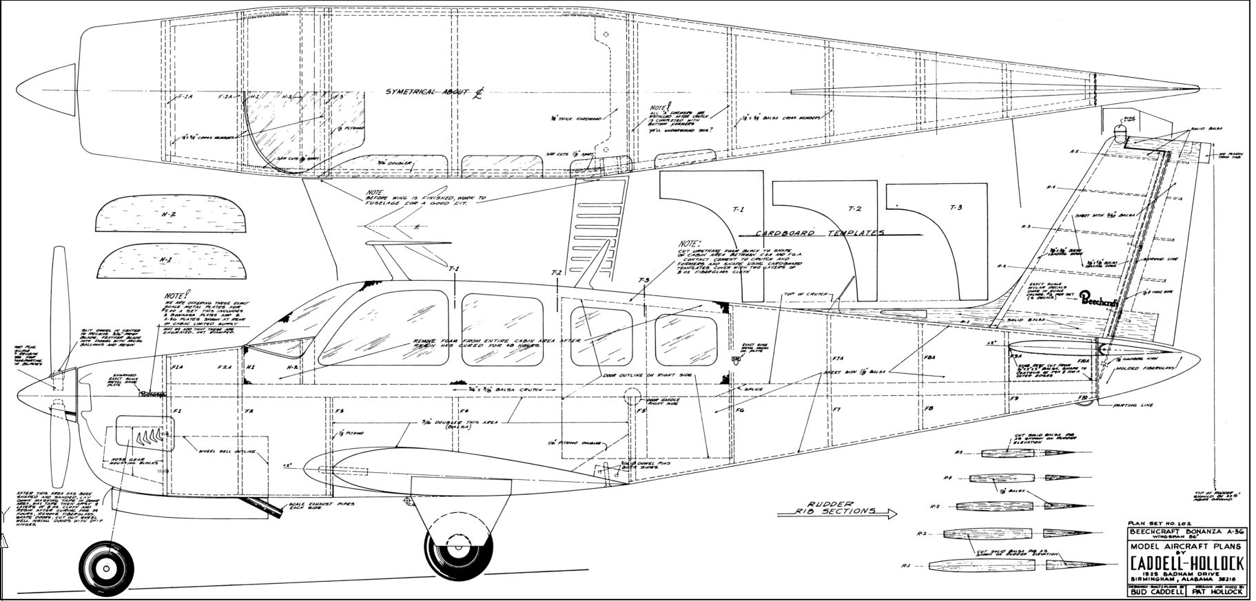
I recently purchased the plans and short kit for 86" Wingspan Bonanza designed by Bud Caddell along with a set of Robart 630BNZ retracts for it. I plan on starting it in the fall or next spring. I haven't decided on a power plant yet except it will be glow.
Mike


http://www.rcuniverse.com/forum/rc-s...l#post12313014 .
I recently purchased the plans and short kit for 86" Wingspan Bonanza designed by Bud Caddell along with a set of Robart 630BNZ retracts for it. I plan on starting it in the fall or next spring. I haven't decided on a power plant yet except it will be glow.
Mike
 03-10-2017, 10:14 PM
#16


Join Date: Mar 2017
Location: Pretoria South Africa
Posts: 141
Likes: 0
Received 0 Likes
on
0 Posts
Fantastic! Another Bonanza build, subscribed! There is another Hosteler currently under construction you can see Gibb's build here:
http://www.rcuniverse.com/forum/rc-s...l#post12313014 .
I recently purchased the plans and short kit for 86" Wingspan Bonanza designed by Bud Caddell along with a set of Robart 630BNZ retracts for it. I plan on starting it in the fall or next spring. I haven't decided on a power plant yet except it will be glow.
Mike
My first time posting on RCU so still gotta get used to it.
I'm actually the builder of this Bonnie, my customer just loaded the thread here to get some international attention as there are quite a few issues with this build and VERY FEW (think only one) threads on this bird and that is very incomplete at this point so not helping me much. What size is the Bonnie you are going to build?
03-11-2017, 04:56 AM
#17

My first time posting on RCU so still gotta get used to it.
I'm actually the builder of this Bonnie, my customer just loaded the thread here to get some international attention as there are quite a few issues with this build and VERY FEW (think only one) threads on this bird and that is very incomplete at this point so not helping me much.
03-11-2017, 06:43 AM
#18
Join Date: Mar 2017
Location: Pretoria South Africa
Posts: 141
Likes: 0
Received 0 Likes
on
0 Posts
These issues are not made up, they are discovered as I have progressed and will progress further.
I will however look at some of the other Hostetler builds and see how those guys have worked through the issues, and like I said before, it's a very nice build for those that like a challenge and have experience.
My customer actually asked me if was still wanting to do the build and I told him straight, I'M NOT SCARED...hey, I can't be, I'm building my second Carl Goldberg Valkyrie at the same time as well as a couple vintage FAI speed planes and a Ben Buckle Super 60.
03-11-2017, 08:23 AM
#19
I found few discrepancies in my Hostetler builds. I did find that I had to analyze each step, and plan five steps ahead.
Note that some kit cutters take liberties with the parts, cutting one piece where the plans may show two, or laminated pieces may be supplied where they aren't shown on the plans.
These are kit cutter issues, and not of the designer's making.
The best advice that I can provide, is to study the plans carefully, making sure that you understand what Wendel intends. Only then would I suggest that you add glue.
Last edited by TomCrump; 03-11-2017 at 08:30 AM.
03-12-2017, 12:23 AM
#20
Join Date: Mar 2017
Location: Pretoria South Africa
Posts: 141
Likes: 0
Received 0 Likes
on
0 Posts
I found few discrepancies in my Hostetler builds. I did find that I had to analyze each step, and plan five steps ahead. Note that some kit cutters take liberties with the parts, cutting one piece where the plans may show two, or laminated pieces may be supplied where they aren't shown on the plans. These are kit cutter issues, and not of the designer's making. The best advice that I can provide, is to study the plans carefully, making sure that you understand what Wendel intends. Only then would I suggest that you add glue.
03-12-2017, 05:55 PM
#21
Hi Mike.
My first time posting on RCU so still gotta get used to it.
I'm actually the builder of this Bonnie, my customer just loaded the thread here to get some international attention as there are quite a few issues with this build and VERY FEW (think only one) threads on this bird and that is very incomplete at this point so not helping me much. What size is the Bonnie you are going to build?
86" wingspan recommended wngine is a .90 to 1.20 2 cycle. I'll decide on the engine once I get the designed modified for Robart retracts. The original designed was built around Rohm retracts and the nose gear had a rather strange looking way of mounting it I can't duplicate with the Robart nose gear.
03-13-2017, 12:27 AM
#22
Thread Starter
Join Date: Mar 2012
Location: Cape Town, SOUTH AFRICA
Posts: 89
Likes: 0
Received 0 Likes
on
0 Posts
Well I got the one side of the fin skinned and the rudder support blocks glued in. The skin is taken past the bottom of the fin to allow for trimming later when the fin gets mated to the sheeted fuselage.
 Rudder hinge supports drying in fin.jpg (86.37 KiB) Viewed 50 times
 One side skinned with rudder hinge supports in.jpg (67.41 KiB) Viewed 50 times
 One side of fin complete.jpg (49.87 KiB) Viewed 50 times
I also made two extra blocks and laminated the elevator horn supports.
 Elevator horn supports laminating.jpg (104.11 KiB) Viewed 50 times
Then I skinned one side of the stab, still have to make the elevator hinge support blocks and glue them in.
 One side of stabilizer complete.jpg (87.71 KiB) Viewed 50 times
Hopefully I'll get more done tomorrow...depends on the overhang after my sons 18th tonight 
I also made two extra blocks and laminated the elevator horn supports.
Then I skinned one side of the stab, still have to make the elevator hinge support blocks and glue them in.
Hopefully I'll get more done tomorrow...depends on the overhang after my sons 18th tonight
03-13-2017, 10:54 PM
#24
Thread Starter
Join Date: Mar 2012
Location: Cape Town, SOUTH AFRICA
Posts: 89
Likes: 0
Received 0 Likes
on
0 Posts
Got the fin sheeting completed and the bit of filling done where needed.
 Fin sheeted and shaped (1).jpg (63.18 KiB) Viewed 6 times
 Fin sheeted and shaped (2).jpg (60.91 KiB) Viewed 6 times
 Filling where needed on fin (1).jpg (68.88 KiB) Viewed 6 times
 Filling where needed on fin (2).jpg (75.15 KiB) Viewed 6 times
Also got the hinge support blocks in on the stab and then sheeted.
 Stabilizer sheeted and shaped (1).jpg (67.24 KiB) Viewed 6 times
 Stabilizer sheeted and shaped (2).jpg (65.96 KiB) Viewed 6 times

And the tail section so far.
 Tail assembly so far.jpg (74.38 KiB) Viewed 6 times
Also got the hinge support blocks in on the stab and then sheeted.
And the tail section so far.